

Page 1

LonBridge Server User’s Guide
®
078-0386-01A
Page 2

Echelon, LONWORKS, LONMARK, LonTalk, Neuron, 3120, 3150,
ShortStack, and the Echelon logo are trademarks of Echelon
Corporation registered in the United States and other
countries. 3170, LonBridge, and OpenLDV are trademarks of
the Echelon Corporation.
Other brand and product names are trademarks or
registered trademarks of their respective holders.
Neuron Chips and other OEM Products were not designed
for use in equipment or systems, which involve danger to
human health or safety, or a risk of property damage and
Echelon assumes no responsibility or liability for use of the
Neuron Chips in such applications.
Parts manufactured by vendors other than Echelon and
referenced in this document have been described for
illustrative purposes only, and may not have been tested
by Echelon. It is the responsibility of the customer to
determine the suitability of these parts for each
application.
ECHELON MAKES AND YOU RECEIVE NO WARRANTIES OR
CONDITIONS, EXPRESS, IMPLIED, STATUTORY OR IN ANY
COMMUNICATION WITH YOU, AND ECHELON SP ECIFICALLY
DISCLAIMS A N Y IMPLIED WARRA NT Y O F ME R C H ANTABILITY
OR FITNESS FOR A PARTICULAR PURPOSE.
No part of this publication may be reproduced, stored in a
retrieval s ystem, or transmitted, in any form or by any means,
electronic, mechanical, photocopying, recording, or
otherwise, without the prior written permission of Echelon
Corporation.
Printed in the United States of America.
Copyright © 2007, 2009 Echelon Corporation.
Echelon Corporation
www.echelon.com
Page 3

Welcome
The Echelon LonBridge™ Server is a software tool that provides an interface
between a TCP/IP network and a network of L
installation (ISI) devices. This interface allows you to create a control
application, such as a graphical user interface (GUI), to manage devices on a
ONWORKS network from a device that is connected to a TCP/IP network.
L
This document describes the LonBridge Server, including how to install it,
configure it, and use the LonBridge application programming interface (API) to
manage and communicate with devices.
Audience
This document assumes that you have a good understanding of the LONWORKS
platform and microcontroller or microprocessor programming.
Related Documentation
The following manuals are available from the Echelon Web site
www.echelon.com) and provide additional information that can help you develop
(
LonBridge applications:
Introduction to the LONW
•
provides an introduction to the ISO 14908 (ANSI/CEA-709.1 and
EN14908) Control Networking Protocol, and provides a high-level
introduction to L
are used for developing, installing, operating, and maintaining them.
ONWORKS networks and the tools and components that
ORKS
System
ONWORKS
®
interoperable self-
(078-0183-01A). This manual
ISI Programmer's Guide
•
(078-0299-01F). Describes how you can use the
Interoperable Self-Installation (ISI) protocol to create networks of control
devices that interoperate, without requiring the use of an installation
tool. Also describes how to use Echelon's ISI Library to develop devices
that can be used in both self-installed as well as managed networks.
ISI Protocol Specification
•
(078-0300-01F). Describes the Interoperable
Self-Installation (ISI) protocol, which is a protocol used to create
networks of control devices without requiring the use of an installation
tool.
•
LONM
®
ARK
Application Layer Interoperability Guidelines.
describes design guidelines for developing applications for open
interoperable L
Web site,
ShortStack User’s Guide
•
to develop an application for a L
ShortStack
ONWORKS devices, and is available from the LONMARK
www.lonmark.org.
(078-0365-01A). This document describes how
®
2.1 Micro Server. It describes the architecture of a
ONWORKS device using Echelon’s
ShortStack device and how to develop a ShortStack device.
®
All of the Echelon documentation is available in Adobe
PDF format. To view the
PDF files, you must have a current version of the Adobe Reader
download from Adobe at:
www.adobe.com/products/acrobat/readstep2.html.
This manual
®
, which you can
LonBridge Server User’s Guide iii
Page 4

iv
Page 5

Table of Contents
Welcome.........................................................................................................iii
Audience ........................................................................................................iii
Related Documentation ................................................................................iii
Introduction........................................................................................................ 1
Introduction.................................................................................................... 2
Getting Started .............................................................................................. 4
Installing the LonBridge Server ...................................................................4
Installation for Windows......................................................................... 4
Installation for Linux .............................................................................. 5
Starting the LonBridge Server...................................................................... 6
Command Line Usage for Windows ....................................................... 6
Command Line Usage for Linux............................................................. 6
Command Line Switches......................................................................... 6
Configuring the LonBridge Server.................................................................... 9
Configuring the LonBridge Server.............................................................. 10
The LonBridge Control Utility ............................................................. 10
The config.xml File ................................................................................ 11
Classes Directory ................................................................................... 13
Instances Directory ............................................................................... 16
Using the LonBridge API................................................................................. 19
Tasks Performed by a LonBridge Application ........................................... 20
Defining Device Classes ........................................................................ 20
Discovering and Communicating with Devices ................................... 20
Tasks Performed by the LonBridge Server ................................................20
Discovering Devices............................................................................... 21
Monitoring and Polling a Network Variable........................................ 21
Updating a Network Variable............................................................... 22
LonBridge API.................................................................................................. 23
LonBridge API.............................................................................................. 24
General Message Format ...................................................................... 24
Expressions ............................................................................................ 25
Tracers.................................................................................................... 25
Errors .....................................................................................................25
Parsing a LonBridge XML Message..................................................... 26
LonBridge Commands for Input Messages.......................................... 27
LonBridge Commands for Output Messages ....................................... 28
XML Schema for the LonBridge API.................................................... 29
Examples................................................................................................30
LonBridge Device Class File............................................................................ 33
LonBridge Device Class File Format .......................................................... 34
XML Elements for a Device Class File................................................. 34
XML Schema for Device Class Files..................................................... 40
Example Device Class File.................................................................... 41
Creating a LonBridge Device Class File..................................................... 43
Example for Creating a Device Class File.................................................. 44
Examine Source Files............................................................................44
Define <attribute> Elements ................................................................ 45
Determine Needed Network Variables ................................................45
LonBridge Server User’s Guide v
Page 6

Define <nv> Elements........................................................................... 46
Use the Resource Editor to Determine Attributes .............................. 47
Determining the Attributes for nvoPower..................................... 48
Determining the Attributes for nviValue and nvoValueFb ......... 50
Define <enum> Elements...................................................................... 53
Browse the XIF File to Determine Indices .......................................... 56
Complete Device Class File................................................................... 59
vi
Page 7

1
Introduction
This chapter introduces the LonBridge Server and describes
how to install it.
LonBridge Server User’s Guide 1
Page 8

Introduction
The Echelon LonBridge Server is a software tool that provides an interface
between a TCP/IP network and a network of L
installation (ISI) devices. This interface allows you to create a control
application, such as a graphical user interface (GUI), to manage devices on a
ONWORKS network from a device that is connected to a TCP/IP network.
L
ONWORKS interoperable self-
LonBridge Server also provides a client-independent application programming
interface (API) for managing these networks and devices. For Microsoft
®
Windows
platforms, the LonBridge Server requires a layer-5 network interface
®
that is compatible with the OpenLDV™ interface, such as the Echelon U20 USB
Network Interface, to manage communications with the L
®
For Linux
platforms, the LonBridge Server requires an Echelon ShortStack
ONWORKS network.
Micro Server (which uses the LDV interface) to manage communications with the
ONWORKS network.
L
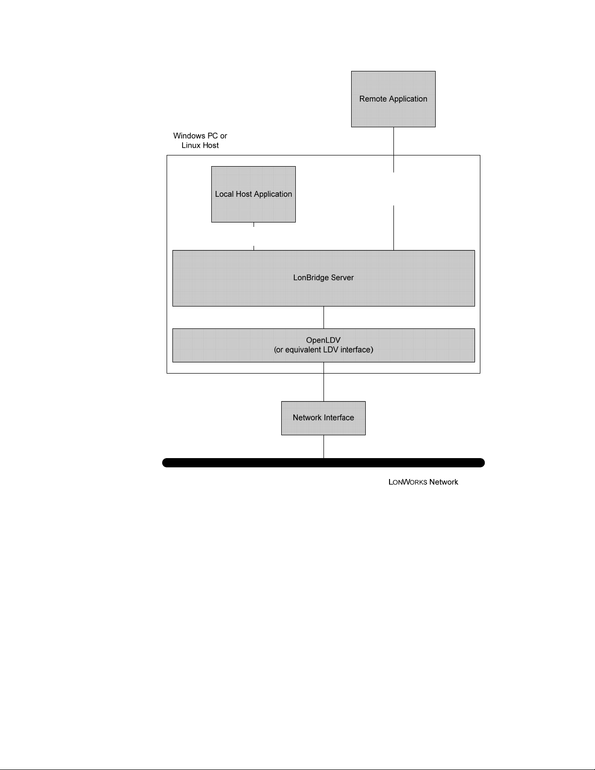
Figure 1 on page 3 is a block diagram of a Windows or Linux host running the
LonBridge Server, and using the OpenLDV or equivalent interface to
communicate with the L
ONWORKS network. The LonBridge Server uses TCP/IP
sockets to communicate with LonBridge applications. The socket interface allows
the LonBridge Server to communicate with applications that are local to the
same host platform as the LonBridge Server and with applications that are
remote (connected by an Ethernet or similar network). This socket interface also
allows you to develop LonBridge client applications with any programming
language that supports TCP/IP socket interfaces.
2 Introduction
Page 9
TCP Socket
TCP
Socket
Figure 1. LonBridge Server
The LonBridge Server provides the following key features:
• Supports networks of ISI devices
• Provides an easy-to-use programmatic interface that is independent of
any client operating system or processor
• Supports multiple, simultaneous clients
• Supports simple set-up for use with home user interface (UI) applications
• Runs on Windows Vista
®
, Windows XP, or Linux hosts
The LonBridge API provides a simple TCP/IP socket interface that you can use
directly as a bridge to a L
ONWORKS network. The LonBridge API supports
development of UI and controller applications that can run on Windows or Linux
platforms. The API consists of a simple set of extensible markup language (XML)
elements that describe L
ONWORKS devices and actions for those devices.
LonBridge Server User’s Guide 3
Page 10

The LonBridge API supports up to 20 local or remote clients. Each client opens a
TCP socket to the LonBridge Server. Clients call functions in the API by sending
a request to the LonBridge Server. The request must be formatted as an XML
string. The API returns a response as an XML string through the same TCP
socket interface. Each client specifies an incoming port to receive event
notifications for device discovery and network variable value changes. All clients
receive all events.
Getting Started
The LonBridge Server software includes a Windows version and a Linux version.
Both versions are available from Echelon Support.
To use the LonBridge Server, perform the following steps:
1. Install the LonBridge Server. See
more information.
2. Configure the LonBridge Server. See Chapter
LonBridge Server
3. Create a device class file for your device. This file describes the interface
for each device that the LonBridge Server supports. See Chapter
, on page 9, for more information.
LonBridge Device Class File
4. Create a LonBridge application using the LonBridge API. See Chapter
LonBridge API
If you have an Echelon Lamp Module or Appliance Module, you can run the
LonBridge Server after step 2. For the Windows version, you can use the
LonHome™ Display Example application to view and manage the Lamp Module
or Appliance Module; for the Linux version running on the Altera
Embedded Evaluation Kit, you can load the example application into the SD
Card and view and manage the Lamp Module or Appliance Module.
, on page 23, for more information.
Installing the LonBridge Server
, on page 33, for more information.
Installing the LonBridge Server
Echelon delivers source code for the LonBridge Server to LonBridge Server
licensees. You can port this source code to any platform. The LonBridge Server
has been ported to, and tested with, the following operating system
environments:
2,
Configuring the
®
Nios® II
for
5,
4,
• Microsoft Windows XP
• Microsoft Windows Vista
• μClinux™ for the Altera Nios II Embedded Evaluation Kit (NEEK)
Installation for Windows
To install the LonBridge Server on a Windows platform, perform the following
steps:
1. Contact Echelon Support to request a license for the LonBridge Server.
2. Download the LonBridge Server from the address supplied by Echelon
Support.
4 Introduction
Page 11

3. Double click the LonBridge140
xxx
in the file name represents the current build number for the
LonBridge Server). The Echelon LonBridge Server 1.4 main installer
window opens.
4. Follow the installation dialogs to install the LonBridge Server onto your
computer.
By default the LonBridge Server is installed in the C:\Program
Files\Echelon\LonBridge Server directory.
In addition to the LonBridge Server, the installation program also installs:
OpenLDV 3.4 Driver
•
and applications with a unified Windows software interface for sending
and receiving LonTalk
interfaces.
LonBridge Control Utility
•
start, and stop the LonBridge Server. This utility is not required to
operate the LonBridge Server, but is useful for setting it up. See
– A Windows driver that provides LONWORKS tools
®
messages through Echelon's family of network
LonBridge Control Utility
utility.
LonHome Display Example
•
uses the LonBridge Server.
The Microsoft .NET Framework 3.5 SP1
•
environment for the LonBridge Control utility. The .NET Framework is
not installed if your PC already has version 3.5 SP1 or later installed.
xxx
Setup.exe file that you downloaded (the
– An application that you can use to configure,
The
on page 10 for more information about this
– An example user interface application that
– The required operating
You can embed the Windows installer for LonBridge Server into your own
product’s installation program, using a silent installation of the LonBridge
Server. Silent installation does not install the OpenLDV driver, the LonHome
Display Example application, the .NET Framework, or the LonBridge
documentation. To perform silent installation, use the /S command-line switch:
LonBridgeSetup.exe /S
The LonBridge Server is installed as a Windows Service. You can set the startup
type for the Service by running the LonBridge Control utility, by modifying the
config.xml file, or from the Windows Services window. See Chapter
Configuring the LonBridge Server
configuring the LonBridge Server.
Installation for Linux
To install the LonBridge Server on a Linux platform, perform the following steps:
1. Contact Echelon Support to request a license for the LonBridge Server.
2. Download the LonBridge Server from the address supplied by Echelon
Support.
3. Decompress the LonBridge140
xxx
(the
LonBridge Server).
4. For a μClinux environment, modify the make file (as needed) and run it
to build the LonBridge Server application. For other Linux distribution
in the file name represents the current build number for the
2,
, on page 9 for more information about
xxx
Source.zip file that you downloaded
LonBridge Server User’s Guide 5
Page 12

environments, you must port the LonBridge Server to that Linux
distribution (see the source code comments for more information).
Starting the LonBridge Server
For the Windows platform, the service for the LonBridge Server generally starts
automatically when the operating system starts, although you can configure the
2,
service to start manually (see Chapter
9, for more information about configuring the LonBridge Server).
page
For either Windows or Linux platforms, you can start the LonBridge Server from
the command line.
Configuring the LonBridge Server
Command Line Usage for Windows
To start the LonBridge Server, if it is not already running as a service:
1. From the Windows command prompt, change directories to the
LonBridge directory: C:\Program Files\Echelon\LonBridge.
2. Enter the LonBridge command.
See
Command Line Switches
for the LonBridge command.
for a listing of the available command-line switches
, on
Command Line Usage for Linux
To start the LonBridge Server:
1. From the Linux command prompt, change directories to the LonBridge
directory.
2. Enter the lonbridge command.
See
Command Line Switches
for the lonbridge command.
for a listing of the available command-line switches
Command Line Switches
Table 1 lists the available command-line switches for the Windows LonBridge
command and the Linux lonbridge command.
The switches for the Windows LonBridge command are not case sensitive; you
can use either lower or upper case. However, the switches for the Linux
lonbridge command are case sensitive.
Table 1. Command-Line Switches for the LonBridge Command
Windows
Switch
/C -c Enables console logging; copies all logged events to the
Linux Switch Description
console.
You can use this option to watch log events in real-time
during development and debugging of your application or of
the LonBridge Server.
6 Introduction
Page 13

Windows
Switch
/D -d Enables debug logging; logs events tracing the internal
/E -e Enables error logging; includes only error events in the log
/G -g Enables general logging; logs general events, such as device
Linux Switch Description
operation of the LonBridge Server. Also enables error and
general logging.
You can use this option when porting or enhancing the
LonBridge Server.
Mutually exclusive with the /E, /G, /N, and /V (-e, -g, -n, and
-v) switches.
file.
Mutually exclusive with the /D, /G, /N, and /V (-d, -g, -n, and
-v) switches.
discovery and startup events in the log file. Also enables
error logging.
The LonBridge Server uses this logging level as the default
unless you specify a different level with one of the log-level
command-line switches, or in the LonBridge configuration
file.
Mutually exclusive with the /D, /E, /N, and /V (-d, -e, -n, and
-v) switches.
/N -n Disables all event logging.
Mutually exclusive with the /D, /E, /G, and /V (-d, -e, -g, and v) switches.
/S Starts the LonBridge Server standalone so that it is not
running as a Windows service.
The LonBridge Server service must be stopped when the
LonBridge Server is run standalone. Running standalone
can be useful during development if you are enhancing the
Windows version of the LonBridge Server.
There is no Linux switch for this option.
/V -v Enables verbose logging; logs detailed events for messages
sent to and received by the LonBridge Server. Also enables
debug, error, and general logging.
You can use this option when porting or enhancing the
LonBridge Server software, especially if you are modifying
the network driver interface.
Mutually exclusive with the /D, /E, /G, and /N (-d, -e, -g, and
-n) switches.
LonBridge Server User’s Guide 7
Page 14

The order of increased level of detail for the event logging switches is:
1. /E (-e)
2. /G (-g): Includes /E (-e)
3. /D (-d): Includes /E (-e) and /G (-g)
4. /V (-v): Includes /E (-e), /G (-g), and /D (-d)
Specifying one of the event logging switches (/D, /E, /G, /N, or /V for Windows, -d,
-e, -g, -n, or -v for Linux) overrides the event-logging value specified in the
LonBridge configuration file (config.xml); see
information about this file.
The config.xml File
on page 11 for
8 Introduction
Page 15

Configuring the LonBridge Server
This chapter describes how you can configure the LonBridge Server.
2
LonBridge Server User’s Guide 9
Page 16

Configuring the LonBridge Server
For the LonBridge Server, you can specify the following configuration
information:
• The L
• The LAN Internet protocol (IP) address
• The LAN IP port
• The L
• The event logging level for the LonBridge Server
This information configures the communications for the LonBridge Server to be
able to communicate with the L
also configures L
You can specify this basic configuration information for the LonBridge Server
either by:
• Running the LonBridge Control utility – for Windows platforms only
• Modifying the LonBridge configuration file (config.xml) – for both
All configuration values have default values, so if you do not specify a configured
value, the LonBridge Server uses the default values described in
on page 11.
File
ONWORKS network interface
ONWORKS network variable polling interval
ONWORKS network and the TCP/IP network. It
ONWORKS polling and event logging.
(available only for accounts that are part of the administrators group)
Windows and Linux platforms
The LonBridge Control Utility
The config.xml
The LonBridge Control utility, shown in Figure 2 on page 11, is a Windows
application program that allows you to specify certain configuration and
operating parameters for the LonBridge Server software and control the
Windows service for the LonBridge Server. The LonBridge Control utility
maintains its settings in the LonBridge configuration file (config.xml).
Important: The LonBridge Control utility is available for Windows platforms
only. In addition, the LonBridge Control utility is a C# application and requires
the Microsoft .NET Framework 3.5 SP1. The Windows installer for the
LonBridge Server automatically installs the necessary .NET Framework.
10 Configuring the LonBridge Server
Page 17
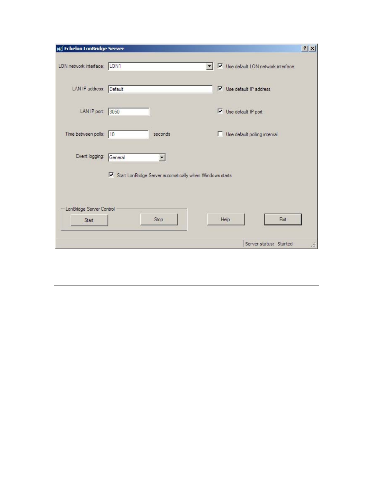
Figure 2. LonBridge Control Utility
See the LonBridge Control utility online help for information about the utility’s
fields and controls.
The config.xml File
The config.xml file contains XML elements that configure the LonBridge Server;
these elements correspond to the GUI controls in the LonBridge Control utility.
You can edit this file using any text editor (such as Windows Notepad or Linux
vi).
If you change any values within the config.xml file while the LonBridge Server is
running, you must stop and restart the server for the changes to take effect.
For a standard installation, this file is in the Windows common application data
directory or the Linux configuration directory:
• For Windows XP: C:\Documents and Settings\All Users\Application
Data\Echelon\LonBridge
• For Windows Vista: C:\Program Data\Echelon\LonBridge
• For Linux: /etc/lonbridge
The default config.xml file contains the following information:
<bridge>
<autostart value="true" />
LonBridge Server User’s Guide 11
Page 18

<interface value="LON1" />
<ip value="default" />
<pollrate value="5" />
<port value="3050" />
<logging value="all" />
</bridge>
<bridge>
The <bridge> element defines the configuration, and is the top-most element
within the config.xml file.
The <bridge> element is required if any of the other child elements are
included, and only one <bridge> element is allowed per configuration file.
<autostart>
The <autostart> element specifies whether the service for the LonBridge
Server starts automatically when the operating system starts. Valid values
are true and false. The default value is true, which enables autostart.
This element applies only to the Windows platform.
<interface>
The <interface> element specifies the name of the network interface that the
LonBridge Server uses to communicate with the L
LonBridge Server uses LON1 as the default L
ONWORKS network. The
ONWORKS network interface.
This element applies only to the Windows platform.
For Linux platforms, the LonBridge Server uses a serial device name (such as
/dev/ttyS0) rather than a L
ONWORKS network interface.
<ip>
The <ip> element specifies the IP address for the LonBridge Server. By
default, the LonBridge Server uses the default IP address (0.0.0.0). This
default address enables the server to listen for IP connections on all IP
addresses for the server’s host computer.
If you specify a specific address (rather than the default), all LonBridge
remote clients must use the same address to communicate with the
LonBridge Server. However, if you specify the default address or 0.0.0.0,
remote clients can use any valid address for the host computer that is
running the LonBridge Server. Local clients can use the 127.0.0.1 loop-back
address.
<pollrate>
The <pollrate> element specifies the number of seconds between polls for
ONWORKS network variables. The LonBridge Server periodically polls the
L
network variables that are defined within the network. Valid values are
between 0 and 60. By default, the LonBridge Server uses a polling interval of
10 seconds.
Example: If the polling interval is 5 seconds per poll and there are 20
network variables to be polled, one network variable will be polled every 5
seconds, and it will take 100 seconds to poll all 20 network variables.
12 Configuring the LonBridge Server
Page 19

<port>
The <port> element specifies the IP port for the LonBridge Server. By
default, the LonBridge Server uses the default IP port (3050).
<logging>
The <logging> element specifies the event logging level for the LonBridge
Server and the LonHome Display Example:
• None – Disables all event logging.
• Error – Enables error logging; includes only error events in the log
file.
• General – Enables general logging; logs general events, such as
device discovery and startup events in the log file. Also enables error
logging.
The LonBridge Server uses this logging level as the default unless
you specify a different level with one of the log-level command-line
switches, or in the LonBridge configuration file.
• Debug – Enables debug logging; logs events tracing the internal
operation of the LonBridge Server. Also enables error and general
logging.
You can use this option when porting or enhancing the LonBridge
Server.
• Verbose – Enables verbose logging; logs detailed events for messages
sent to and received by the LonBridge Server. Also enables debug,
error, and general logging.
You can use this option when porting or enhancing the LonBridge
Server software, especially if you are modifying the network driver
interface.
By default, the LonBridge Server uses general logging. However, if you start
the LonBridge Server from the command line and specify any of the event
logging switches (/D, /E, /G, /N, or /V for Windows, -d, -e, -g, -n, or -v for
Linux), the LonBridge Server uses the specified event logging level,
regardless of the event logging level specified in the configuration file.
The event log is named LonBridge.log. This file is created in the Windows
common application data directory or the Linux configuration directory.
In addition to the data within the LonBridge configuration file, the LonBridge
Server also provides two directories of XML files that describe L
devices that the LonBridge Server can manage: the Classes directory and the
Instances directory. You can find these directories in the same Windows common
application data directory or the Linux user directory as the config.xml file.
Classes Directory
The Classes directory contains XML files that describe the inputs and outputs for
specific classes of devices (such as Echelon Lamp Modules or Appliance Modules).
When the LonBridge Server discovers a new device, the LonBridge Server reads
ONWORKS
LonBridge Server User’s Guide 13
Page 20

the program ID from the new device and then searches the device class files for a
matching program ID. If the LonBridge Server finds a matching program ID, the
LonBridge Server stores information about the discovered device in the
devices.xml file in the Instances directory (see
Each class file describes the device interface for a specific program ID, similar to
a LONWORKS device external interface (XIF) file. However, unlike XIF files, the
class files are XML files that identify only those network variables that the
LonBridge Server monitors or controls. That is, the class files do not necessarily
include all of the network variables that are available on the device. In addition,
the class files specify whether a network variable should be polled by or bound to
the LonBridge Server.
Instances Directory
on page 16).
A standard installation includes the class files listed in
Table 2. Class Files
Class File Application Program ID
AM1_LNS_S04.xml Appliance Module 9F:FE:57:1E:28:06:10:00
AM2L_LNS_S04.xml Appliance Module 9F:FE:57:1E:28:06:10:60
AMDR_LNS_S04.xml Lamp Module 9F:FE:57:1E:00:0A:10:40
blinds.xml Sun Blind Actuator 9F:FF:FF:05:01:06:11:08
isiappliance.xml Echelon 3120® Appliance
Module
isiappliance2.xml Example Appliance
Module
isiappliance3.xml Echelon 3170™
Appliance Module
isiblinds.xml Example Blinds 9F:FF:FF:3D:0C:40:11:00
Table 2.
90:00:01:1E:29:4A:11:01
9F:FF:51:1E:00:4A:11:08
90:00:01:1E:29:46:11:03
isiblinds2.xml Sienna AM2 3170
Sunblinds
isiblinds3.xml Echelon Mini PL 3150®
Sunblinds
isikeypad.xml Nico Keypad 90:00:B5:20:35:41:11:01
isikeypad2.xml Nico Keypad 90:00:B5:20:35:41:11:00
isilampmodule.xml Echelon 3120 Lamp
Module
isilampmodule2.xml Example Lamp Module 9F:FF:51:1E:00:4A:11:00
14 Configuring the LonBridge Server
9F:FF:FF:3D:0C:44:11:03
9F:FF:FF:3D:0C:46:11:03
90:00:01:1E:29:49:11:02
Page 21

Class File Application Program ID
isilampmodule3.xml Echelon 3170 Lamp
Module
isilampmodule4.xml Example Mini PL 3120
Lamp
isilampmodule5.xml Example Mini PL 3150
Lamp
isilampmodule6.xml Echelon Mini FT 3150
Lamp
isilight2.xml Echelon ISI Lamp
Module
isioccupancy.xml Example Occupancy
Sensor
isioccupancy2.xml Example Mini PL 3150
Occupancy Sensor
kdmotion.xml KD Motion Detector 9F:FE:4C:32:00:03:11:01
lampmodule.xml Echelon Lamp Module 90:00:01:1E:28:06:11:02
90:00:01:1E:29:4F:11:03
9F:FF:FF:1E:29:41:11:03
9F:FF:FF:1E:29:4F:11:03
9F:FF:FF:1E:29:4F:04:03
9F:FF:51:1E:00:4A:11:18
9F:FF:FF:0A:3D:40:11:00
9F:FF:FF:0A:3D:40:11:03
mat.xml MAT Switch 90:00:00:07:00:06:11:11
samsunggas.xml Samsung Gas Valve 90:00:6E:4E:39:8A:10:03
sm_2btn_act.xml Samsung Two Relay
Lamp
sm_2btn_sw.xml Samsung Two Button
Switch
sm_4btn_sw.xml Samsung Four Button
Switch
sm_sw_act.xml Samsung Two Relay
Lamp
swleg.xml Samsung Switched Leg
Lamp Module
thermostat.xml Smart Controls
Thermostat
washingmachine.xml Example Washing
Machine
9F:FF:FF:1E:00:05:10:02
9F:FF:FF:20:00:05:10:02
9F:FF:FF:20:00:05:10:04
90:00:00:20:00:05:10:00
90:00:01:1E:28:06:11:04
30:31:38:34:76:31:36:31
9F:FF:FF:96:0B:05:11:00
LonBridge Server User’s Guide 15
Page 22

To add a new device for the LonBridge Server to monitor or control, add an XML
file for the device to the Classes directory. See Chapter
Class File
devices and for an example class file.
To modify which network variables the LonBridge Server monitors or controls for
a device, edit the appropriate device class file with any text editor.
You must stop and restart the LonBridge Server whenever you add or change a
device class file.
, on page 34, for information about the XML elements that describe
Instances Directory
The Instances directory contains a single file (devices.xml) that the LonBridge
Server maintains. This file contains all of the devices that the LonBridge Server
has ever discovered.
Devices remain in this file even if they are no longer available. Each device has
an active attribute which specifies whether the LonBridge Server has received
any updates from the device recently. Thus, you can name a device, add
attributes to the device, or take the device offline (for example, to relocate it), and
your user-added attributes remain persistent in the devices.xml file.
Example File:
<devices>
<device nid="050182DC6900" id="0" fblock="-1" type="dimmer"
name="Lamp Module" brand="Echelon" active="false"
brightness="44" state="off" power="0" energy_hi="8"
energy_lo="5260" />
<device nid="0500FA901E00" id="1" fblock="-1" type="switch"
name="Washing Machine" brand="Echelon" active="true"
state="on" power="0" energy="136" />
<device nid="050182D38600" id="2" fblock="-1" type="switch"
name="Appliance Module 1" brand="Echelon"
active="marginal" state="off" power="0"
energy_hi="0" energy_lo="7195" />
<device nid="050182D37D00" id="3" fblock="-1" type="dimmer"
name="Lamp Module1" brand="Echelon"
active="true" brightness="42" state="on" power="0"
energy_hi="1" energy_lo="4883" />
<device nid="0501452B9A00" id="4" fblock="-1"
type="unknown" name="NEEK 1" brand="LonWorks"
active="false" />
</devices>
5,
LonBridge Device
For each device, the file includes:
• The device’s Neuron ID (the nid attribute), retrieved from the device.
• An ID number (the id attribute), sequentially assigned by the LonBridge
Server. The ID is used by the LonBridge Server and by LonBridge client
applications to identify a specific device for a LonBridge API command.
• The device’s type, name, and brand (the type, name, and brand
attributes), retrieved from the device class file; type is set to “unknown”
for devices that do not match any device class file.
16 Configuring the LonBridge Server
Page 23

• An indication of the device’s state within LonBridge (the active attribute);
this attribute can have one of the following values:
o active=true to specify that LonBridge can communicate with the
device
o active=pending to specify that LonBridge has not yet established
communications with the device; this value is set during
LonBridge startup, while it is establishing communications with
all known devices
o active=marginal to specify that LonBridge has temporarily lost
communications with the device, and is attempting to reestablish
communications
o active=false to specify that LonBridge has lost communications
with the device and cannot reestablish communications
• Other attributes retrieved from the device class file (such as the
brightness attribute for a lamp).
Although you should not need to edit this file, you can use any text editor to
modify it. This file can be useful during debugging for LonBridge application
development.
You can also delete or rename the file to force the LonBridge Server to rediscover
devices. You must stop the LonBridge Server before deleting or editing the file.
If you delete the file, it will be recreated when you restart the LonBridge Server.
LonBridge Server User’s Guide 17
Page 24

Page 25

3
Using the LonBridge API
This chapter describes the tasks performed by a LonBridge
application and by the LonBridge Server. A LonBridge application
uses the LonBridge API to manage and communicate with L
devices.
ONWORKS
LonBridge Server User’s Guide 19
Page 26

Tasks Performed by a LonBridge Application
Using the LonBridge API, a LonBridge application can discover manage
ONWORKS interoperable self-installation (ISI) devices on a LONWORKS network,
L
communicate with the devices, and communicate with the LonBridge Server
about the devices.
Defining Device Classes
The Classes directory contains device class files that describe classes of devices
that the LonBridge Server supports. A specific LonBridge application can add
support for additional classes of devices by creating additional files in the Classes
directory.
5,
See Chapter
the LonBridge device class file format.
LonBridge Device Class File
, on page 34, for information about
Discovering and Communicating with Devices
The LonBridge API defines a set of XML elements for sending commands to the
LonBridge Server and receiving responses from the LonBridge Server. It also
includes commands for discovering devices and for communicating with devices.
The API provides commands that allow an application to perform the following
tasks:
• Request that LonBridge perform device discovery
• Retrieve information about a device
• Read data from a device
• Write data to a device
In addition, the API provides commands that allow an application to define
tracers to identify and filter messages.
See Chapter
4,
LonBridge API
, on page 23, for information about the API.
Tasks Performed by the LonBridge Server
When the LonBridge Server starts, it initializes a network interface. The
network interface can be any network interface running a layer-5 MIP or the
layer-6 ShortStack Micro Server.
By default, a LonBridge Server built for the Windows platform communicates
with a network interface with a layer-5 MIP through the OpenLDV network
driver. For example, the Echelon U20 USB Network Interface includes a layer-5
MIP and is supported by the OpenLDV network driver.
By default, a LonBridge Server built for the Linux platform communicates with a
network interface running a ShortStack Micro Server through an LDV
compatible network driver. For example, the LonBridge Server can be built for
the Altera Nios II Embedded Evaluation Kit (NEEK) attached to an Echelon PL
3120 or 3150 EVB Evaluation Board running the ShortStack Micro Server.
20 Using the LonBridge API
Page 27

The LonBridge Server reads the LonBridge configuration file to determine the
name of the network interface (such as LON1) for a layer-5 MIP interface, or the
serial device name (such as /dev/ttyS0) for a ShortStack interface. The
LonBridge Server cannot share a network interface with other applications. If
the network interface is already in use by another application, the LonBridge
Server waits for the network interface to become available.
The LonBridge Server discovers ISI devices, and for each discovered device
searches for a device class file with a matching program ID.
The LonBridge Server includes an ISI domain address server (DAS). The domain
address server coordinates assignment of unique domain IDs and maintains and
distributes an estimate of network size to optimize use of available channel
bandwidth. The domain address server broadcasts timing guidance messages
that provide an estimate of network size and topology as defined by the
Protocol Specification
.
Discovering Devices
The LonBridge Server discovers devices in a LONWORKS network and maintains
a table of all discovered devices. Properties for each device include the device
name, program ID, network variables, and network variable fields. The
LonBridge Server supports up to 200 devices.
ISI
The LonBridge Server can discover devices using either (or both) of the following
methods:
ISI Device Discovery
•
periodic messages sent by all ISI devices called
messages
device containing the device’s Neuron ID and logical network address.
Devices can change their logical network address at any time, and report the
changed address through an updated DRUM. The LonBridge Server updates
device address information when a change is reported by a DRUM.
When the LonBridge Server receives a DRUM with a Neuron ID that it has
not previously discovered, it reads the program ID from the device and
searches for a matching device class file. If the LonBridge Server finds a
matching device class file, it adds the device to a local device table that serves
as a cache for all discovered devices.
Broadcast Device Discovery
•
discover all devices in a network. This function provides accelerated device
discovery, but increases network usage for a short period. The LonBridge
Server can discover all unconfigured devices and all devices within a specified
domain. As with ISI device discovery, only devices with matching device
class files are discovered.
(DRUMs). The DRUM is a periodic message sent by every ISI
: The LonBridge Server discovers ISI devices using
device resource usage
: The LonBridge API provides a function to
Monitoring and Polling a Network Variable
Based on properties defined in the device class files, the LonBridge Server
monitors specified network variables on all devices in the device table, and
reports value changes to LonBridge applications. For layer-5 MIP devices, each
device can have up to up to 4096 network variables. For ShortStack devices,
each device can have up to up to 254 network variables.
LonBridge Server User’s Guide 21
Page 28

The monitoring method can be specified for each specified network variable. The
method can be either passive monitoring (with a layer-5 MIP only) or polled
updates:
• For passive monitoring, the LonBridge Server silently joins connections
for network variables that are enrolled in connections. With passive
monitoring, the LonBridge Server receives event-driven updates to a
network-variable output as it is updated, as long as the network variable
is enrolled in a connection to an input network variable on another
device. This method works only with a layer-5 MIP.
• For polled updates, the LonBridge Server polls network variables at a
default polling period that is specified in the LonBridge configuration file.
The polling period is the interval per poll, that is, if a polling interval of 5
seconds per poll is specified, and there are 20 network variables to be
polled, one network variable will be polled every 5 seconds, and it will
take 100 seconds to poll all 20 network variables.
The network variables to be monitored are specified in a device class file. Each
device class file specifies a program ID for the class definition; the LonBridge
Server uses the program ID to match discovered devices against available device
class files. When a new device is discovered, the LonBridge Server searches the
device class files for file with a matching program ID. If none is found, passive
monitoring is not enabled and the device is not regularly polled. Network
variable values can be reported in raw format or with an optional format.
If a network variable fails to respond to a series of poll requests, the LonBridge
Server marks that device inactive. The device remains inactive until it sends a
DRUM message to the LonBridge Server or responds to a device discovery
request.
Updating a Network Variable
The LonBridge API provides a command to update a network variable or a
network variable field. Use the <attribute> element within a device class file to
define formats for network variable values and network variable field values.
When your application updates a field within a network variable, the application
should update all of the fields for that network variable (all fields for which the
device class file includes an <attribute> element). When the application receives
changes to a network variable or network variable field from a device, the
application should cache the values and merge incoming updates with current
values before presenting the values to a graphical user interface or other
application.
22 Using the LonBridge API
Page 29

4
LonBridge API
This chapter describes the LonBridge application
programming interface (API) for input and output messages.
LonBridge Server User’s Guide 23
Page 30

LonBridge API
The communications between the LonBridge Server and various LonBridge
applications uses the LonBridge API. This API consists of XML strings
(commands) passed as messages between the LonBridge Server and a LonBridge
application.
Each message is a well-formed XML string with a <lon> element as the top-most
element.
Table 3 lists the commands that form the LonBridge API.
Command Message Type Description
<discover> Output Instructs the LonBridge Server to perform device
<error> Input Allows the LonBridge application to specify error
<get> Output Retrieves an object and its attributes with
<is> Input Announces the current value of the attributes for
Table 3. LonBridge API Commands
discovery
conditions
optional matching criteria
a device
<is_new> Input Announces new devices
<is_pending> Input Announces the value of an object before any
<lon> Input or
Output
<set> Output Modifies one or more objects
General Message Format
Each XML element that defines a message (that is, all elements other than the
<lon> element) can use either of the following formats for the element name:
• Element name (for example, <get>)
• Object name concatenated with the element name (for example,
<o1.get>)
The
object.element
device. Object names must start with the letter
the ID (id attribute) specified for the device by LonBridge. A <get> message
message format allows you to send the message to a specific
change has occurred
Defines the LonBridge XML message
o
plus a number. This number is
24 LonBridge API
Page 31

retrieves the id attribute; you can also view the id attribute in the devices.xml
file (see
Instances Directory
Expressions
Expressions are used in the where attribute of the <get> message. The
conditional operators include:
• and
• or
• >
• >=
• ==
• !=
Operators are processed from left to right. However, you can use parentheses to
group conditions.
Tracers
on page 16).
A
tracer
is a special attribute that you can use to identify a specific message, so
that the LonBridge application can filter the message response from other
responses it receives. A tracer is any attribute that includes an underscore (_)
prefix. You can use tracers for LonBridge API messages (called
or for a LonBridge device class file (called
Example for a message tracer:
<lon _mytracename="Turn on a light">
<o43.get _mytraceid="34"
_mytracetimestamp="090803121356"/>
</lon>
...
<lon _mytracename="Turn on a light">
<o43.is brightness="100" _mytraceid="34"
_mytracetimestamp="090803121356"/>
</lon>
Subsequent queries do not return the same tracers:
<lon>
<o43.get/>
</lon>
...
<lon>
<o43.is brightness="100"/>
</lon>
node tracers
).
message tracers
)
Errors
The LonBridge Server reports errors using the <error> element. The <error>
element contains a message that describes the error. There are no fixed
attributes for the <error> element.
LonBridge Server User’s Guide 25
Page 32

Examples:
Error deleting non-existing object:
<lon _tt="54321">
<o73.delete/>
<o77.delete/>
</lon>
...
<lon _tt="54321">
<error description="Object does not exist" code="1">
<o73.delete/>
</error>
</lon>
...
<lon>
<core2.lon1.o77.is_deleted/>
</lon>
More complex error reporting:
<lon>
<o90.turnon/>
<o73.delete/>
</lon>
...
<lon>
<error description="Method does not exist on this object"
code="6">
<o90.turnon/>
</error>
</lon>
...
<lon>
<error description="Object does not exist" code="1">
<o73.delete/>
</error>
</lon>
Parsing a LonBridge XML Message
To parse a LonBridge XML message, a LonBridge application can use a XML
parser or a custom parsing routine. For example, you could base a parsing
routine on the following ECMAScript function:
function parse_node(name) {
p = name.split('.');
if (p.length > 4) {
return null;
}
var properties = new Array("domain", "client", "object",
"method");
o = {domain: null, client: null, method: null,
object: null};
posProperty = 3;
for(i = p.length - 1; i >= 0; i--) {
o[properties[posProperty]] =
p[i] != null && p[i].length > 0) p[i] : null;
26 LonBridge API
Page 33

posProperty--;
}
}
LonBridge Commands for Input Messages
The LonBridge Server sends messages to a LonBridge application for either of
the following reasons:
• In response to specific LonBridge command
• To notify the LonBridge application of events, such as device discovery or
a property update
An application cannot send input messages.
The LonBridge XML for input messages includes the following XML elements:
<error>
The <error> message allows the LonBridge application to specify error
conditions, for example, for a GUI.
Table 4 lists the attributes for the <error> message.
Table 4. Attributes for the <error> Message
Attribute Description Required?
code Specifies the error code. Optional
description Specifies the error description. Optional
<is>
The <is> message announces the current value of the attributes for a device.
This message is used only for devices with a non-empty domain.
The attributes for the <is> message vary depending on the device and the
original output message for which this message is the response. The reported
attributes include a fixed set of attributes that identify the device, followed
by the attributes defined within the <device> element in the devices.xml file.
The fixed and variable attributes are defined in
16.
<is_new>
The <is_new> message announces new devices.
The attributes for the <is_new> message vary depending on the device. The
reported attributes include a fixed set of attributes that identify the device,
followed by the attributes defined within the <device> element in the
devices.xml file. For example, the device name comes from the name
attribute. The fixed and variable attributes are defined in
Directory
on page 16.
Instances Directory
Instances
on page
<is_pending>
The <is_pending> message announces the value of an object before any
change has occurred. This message allows the LonBridge Server to
acknowledge receipt of an output message so that a LonBridge application
LonBridge Server User’s Guide 27
Page 34

can act on the change (for example, update a GUI window) without waiting
for the response from the remote L
The <is_pending> message is usually followed by the <is> message.
The attributes for the <is_pending> message vary depending on the device
and the original output message for which this message is the response. The
reported attributes include a fixed set of attributes that identify the device,
followed by the attributes defined within the <device> element in the
devices.xml file. The fixed and variable attributes are defined in
Directory
<lon>
The <lon> element defines the LonBridge XML message, and is the top-most
element for the message.
The <lon> element is required, and only one <lon> element is allowed per
message.
on page 16.
ONWORKS device.
LonBridge Commands for Output Messages
A LonBridge application sends LonBridge output messages to the LonBridge
Server to manage and communicate with devices within the L
The LonBridge XML for output messages includes the following XML elements:
<discover>
ONWORKS network.
Instances
The <discover> message instructs the LonBridge Server to perform device
discovery.
<get>
The <get> message retrieves an object and its attributes with optional
matching criteria. If no object or criteria is specified, the LonBridge Server
returns all objects and their attributes. If an object or criteria is specified
but, no objects match the criteria, the LonBridge Server returns an empty
message (that is, <lon></lon>).
Table 5 lists the attributes for the <get> message.
Table 5. Attributes for the <get> Message
Attribute Description Required?
select Specifies a comma-separated list of
returnable attribute names. If omitted, all
attributes are returned.
where Specifies an expression that must evaluate
to TRUE for the attribute to be returned.
<lon>
Optional
Required if
select is
specified
The <lon> element defines the LonBridge XML message, and is the top-most
element for the message.
28 LonBridge API
Page 35

The <lon> element is required, and only one <lon> element is allowed per
message.
<set>
The <set> message modifies one or more objects. The LonBridge Server
stores the specified attribute values, and overwrites any existing attribute
values. You cannot delete attributes from an object.
Whenever a <set> message causes any change to an object, the LonBridge
Server broadcasts the <is_pending> message for that object, followed by the
<is> message when the device responds that the change is complete.
This LonBridge Server returns an error if the <set> message fails or if any of
the attribute changes cannot be completed.
Table 6 lists the attributes for the <set> message.
Table 6. Attributes for the <set> Message
Attribute Description Required?
id Specifies the ID for the device. Optional
state Specifies the state for the device. Optional
XML Schema for the LonBridge API
To allow you to create well-formed XML documents for LonBridge messages, this
section provides an XML Schema Definition (XSD) that defines the basic syntax
for the LonBridge API. This schema definition does not include definitions for
object.element
the
for tracers (see
<?xml version="1.0" encoding="UTF-8" ?>
<xs:schema xmlns:xs="http://www.w3.org/2001/XMLSchema">
<xs:element name="discover" type="xs:string" />
<xs:element name="error">
<xs:complexType>
<xs:attribute name="code" type="xs:string" use="optional" />
<xs:attribute name="description" type="xs:string" use="optional" />
<xs:anyAttribute />
</xs:complexType>
</xs:element>
<xs:element name="get">
<xs:complexType>
<xs:attribute name="select" type="xs:string" use="optional" />
<xs:attribute name="where" type="xs:string" use="optional" />
</xs:complexType>
</xs:element>
<xs:element name="is">
<xs:complexType>
<xs:anyAttribute />
message format (see
Tracers
on page 25).
General Message Format
on page 24) or
LonBridge Server User’s Guide 29
Page 36

</xs:complexType>
</xs:element>
<xs:element name="is_new">
<xs:complexType>
<xs:anyAttribute />
</xs:complexType>
</xs:element>
<xs:element name="is_pending">
<xs:complexType>
<xs:anyAttribute />
</xs:complexType>
</xs:element>
<xs:element name="lon">
<xs:complexType>
<xs:choice>
<xs:element ref="discover" />
<xs:element ref="error" />
<xs:element ref="get" />
<xs:element ref="is" />
<xs:element ref="is_new" />
<xs:element ref="is_pending" />
<xs:element ref="set" />
<xs:any minOccurs="0" />
</xs:choice>
<xs:anyAttribute/>
</xs:complexType>
</xs:element>
<xs:element name="set">
<xs:complexType>
<xs:attribute name="id" type="xs:NMTOKEN" use="optional" />
<xs:attribute name="state" type="xs:NMTOKEN" use="optional" />
<xs:anyAttribute />
</xs:complexType>
</xs:element>
</xs:schema>
Examples
Example for the <get> Message:
Query object 57:
<lon>
<o57.get/>
</lon>
...
<lon>
<lon1.o57.is type="light" name="Outdoor Lights"
state="on" brightness="100" address="488484393"/>
</lon>
Select attributes:
<lon>
<get select="name,state,brightness" where="type=='light'
and name=='/S.*/'"/>
30 LonBridge API
Page 37

</lon>
Example for the <set> Message:
<o17.set brightness="60"/>
...
<o17.is_pending brightness="60"/>
LonBridge Server User’s Guide 31
Page 38

Page 39

5
LonBridge Device Class File
This chapter describes the XML elements for the LonBridge
device class file and how to create a device class file.
LonBridge Server User’s Guide 33
Page 40

LonBridge Device Class File Format
A LonBridge device class file is an XML document that the LonBridge Server
uses to define the interface for a device interface for a specified program ID.
When a device is discovered, the LonBridge Server searches the Classes directory
for a device class file with a matching program ID (see
13).
Table 7 lists the XML elements that a device class file includes.
Table 7. XML Elements for a Device Class File
Element Description
<attribute> Defines the attributes for a device
<attributes> Is a container element for the device attributes that are present
on the device
<byte> Defines the fields within a network variable
<device> Defines the device class, and is the top-most element within a
class file
<enum> Enumerates each network variable defined for an <attribute>
element
Classes Directory
on page
<nv> Defines the bytes that are sent on the LONWORKS network for a
network variable update to the device
<nvs> Is a container element for the network variables defined for each
<attribute> element
XML Elements for a Device Class File
<attribute>
The <attribute> element defines the attributes for a device.
For an <attribute> element within a <byte> element, the attribute name
must map an <attribute> element that is defined within the <attributes>
element.
Table 8 lists the attributes for the <attribute> element.
Table 8. Attributes for the <attribute> Element
Attribute Description Required?
enum Defines whether the attribute has an
enumeration of values within an enclosed
set of <enum> elements.
Optional
34 LonBridge Device Class File
Page 41

Attribute Description Required?
length Defines the length of an input network
variable.
Example: For a network variable with a
length of 2, the <byte> element maps
attributes to bytes 0 and 1.
name Defines the name for the attribute. Required
scale Defines a percentage by which to scale the
value.
Example: If the server reads a value of 200
from a device while polling brightness, and
it has a scale value of 50 for that byte, then
the LonBridge XML for messages will
display the brightness as 100 (50% of 200 is
100).
value Defines an absolute value for the byte to be
updated for a network variable.
The value attribute is used only for input
network variables.
Example 1:
<attributes>
<attribute name="brightness">
<nvs>
<nv ... />
</nvs>
</attribute>
</attributes>
Optional
Optional
Optional
Example 2:
<nvs>
<nv ... >
<byte ...>
<attribute name="brightness" enum="true">
<enum ... />
</attribute>
</byte>
</nv>
</nvs>
<attributes>
The <attributes> element is a container element for the device attributes that
are present on the device. It also contains the network variables that are
used for input and output.
At least one <attribute> element, with one or more <nv> elements within the
<nvs> element, must be defined for a specific <attributes> element.
LonBridge Server User’s Guide 35
Page 42

Example:
<attributes>
<attribute ... >
<nvs>
<nv ... />
</nvs>
</attribute>
</attributes>
<byte>
The <byte> element defines the fields within a network variable.
Table 9 lists the attributes for the <byte> element.
Table 9. Attributes for the <byte> Element
Attribute Description Required?
index Specifies the starting byte of the network-
Required
variable. Index 0 is the first byte.
length Defines the number of bytes within the
Optional
input network variable.
value Defines the value of the byte, if any. Optional
Example:
<nvs>
<nv ... >
<byte index="0" length="1">
<attribute ... />
</byte>
</nv>
</nvs>
<device>
The <device> element defines the device class, and is the top-most element
within a class file.
Only one <device> element is allowed per class file.
Table 10 lists the attributes for the <device> element.
Table 10. Attributes for the <device> Element
Attribute Description Required?
brand Defines the manufacturer name of the
Optional
device.
name Defines the name of the device. Required
36 LonBridge Device Class File
Page 43

Attribute Description Required?
pid Defines the program ID for the device
Required
class.
During device discovery, LonBridge Server
maps the program ID of the class to the
program ID of the discovered device.
type Defines the type of the device. Required
Example:
<device pid="9000011E294F1103" name="Lamp Module"
type="dimmer" brand="Echelon">
<attributes>
<attribute ... >
<nvs>
<nv ... />
</nvs>
</attribute>
</attributes>
<nvs>
<nv ... >
<byte ... >
<attribute ... />
</byte>
</nv>
</nvs>
</device>
<enum>
The <enum> element defines logical names for each network variable defined
for an <attribute> element. When an <attribute> element has an enum
attribute set to “true”, the LonBridge Server sets the corresponding
LonBridge XML attribute to a value based on the <enum> children elements
within the <attribute> element.
Table 11 lists the attributes for the <enum> element.
Table 11. Attributes for the <enum> Element
Attribute Description Required?
input For an input network variable, defines the
Required
LonBridge XML value used to set the
device. You can also specify an input as
"default", which indicates that the
LonBridge Server should use this value if
none of the other enumerations match.
For an output network variable, defines the
bytes to be put on the L
ONWORKS network
for this byte.
LonBridge Server User’s Guide 37
Page 44

Attribute Description Required?
output For an input network variable, defines the
bytes to be put on the L
ONWORKS network
for this byte.
For an output network variable, defines the
LonBridge XML value used to set the
device.
value Defines the value of the byte, if any. Optional
Example:
<nvs>
<nv ... >
<byte ... >
<attribute name="state" enum="true">
<enum input="off" output="0" />
<enum input="on" output="1" />
</attribute>
</byte>
</nv>
</nvs>
<nv>
The <nv> element defines the bytes that are sent on the L
ONWORKS network
for a network variable update to the device.
Optional
Table 12 lists the attributes for the <nv> element.
Table 12. Attributes for the <nv> Element
Attribute Description Required?
direction Defines whether the network variable is an
Required
input NV or an output NV. This attribute
is device-centric.
index Correlates the network variable index on
Required
the device with the network variable
defined in the class file.
size Defines the size of the network variable
Optional
update.
Example: To turn on a SNVT_switch
network variable, you send a two byte
message (one byte represents the
brightness and the other byte represents
the state). The size attribute for this NV is
2.
38 LonBridge Device Class File
Page 45

Attribute Description Required?
type Specifies the type for the network variable.
If the network variable is a configuration
network variable (CPNV), the type can be a
configuration property type.
If the type name is SCPTname1,
SCPTname2, or SCPTname3, the
LonBridge Server reads the network
variable to get the device name for the
device. If more than one name string is
available, the LonBridge Server
concatenates them.
If the type name is SCPTlocation, the
LonBridge Server reads the network
variable to get the location name for the
device.
Other network variable and configuration
property types are ignored.
Example:
<nvs>
<nv index="0" direction="input" size="3">
<byte index="0" ... >
<attribute ... >
<enum ... />
</attribute>
</byte>
<byte index="1" ... >
<attribute ... />
</byte>
<byte index="2" ... >
<attribute ... />
</byte>
</nv>
</nvs>
Optional
<nvs>
The <nvs> element is a container element for the network variables defined
for each <attribute> element.
Example:
<nvs>
<nv ... >
<byte ... >
<attribute />
</byte>
</nv>
</nvs>
LonBridge Server User’s Guide 39
Page 46

XML Schema for Device Class Files
To allow you to create well-formed XML documents for device class files, this
section provides an XML Schema Definition (XSD) that defines the basic syntax
for a LonBridge device class file.
<?xml version="1.0" encoding="UTF-8" ?>
<xs:schema xmlns:xs="http://www.w3.org/2001/XMLSchema">
<xs:element name="attribute">
<xs:complexType>
<xs:choice>
<xs:element ref="enum" />
<xs:element ref="nvs" />
</xs:choice>
<xs:attribute name="name" type="xs:NMTOKEN" use="required" />
<xs:attribute name="length" type="xs:NMTOKEN" use="optional" />
<xs:attribute name="enum" use="optional" >
<xs:simpleType>
<xs:restriction base="xs:NMTOKEN">
<xs:pattern value="true|false" />
</xs:restriction>
</xs:simpleType>
</xs:attribute>
<xs:attribute name="scale" type="xs:NMTOKEN" use="optional" />
<xs:attribute name="value" type="xs:NMTOKEN" use="optional" />
</xs:complexType>
</xs:element>
<xs:element name="attributes">
<xs:complexType>
<xs:sequence>
<xs:element ref="attribute" maxOccurs="unbounded" />
</xs:sequence>
</xs:complexType>
</xs:element>
<xs:element name="byte">
<xs:complexType>
<xs:sequence>
<xs:element ref="attribute" minOccurs="0" maxOccurs="unbounded" />
</xs:sequence>
<xs:attribute name="index" use="required" >
<xs:simpleType>
<xs:restriction base="xs:nonNegativeInteger">
<xs:minInclusive value="0" />
<xs:maxInclusive value="4095" />
</xs:restriction>
</xs:simpleType>
</xs:attribute>
<xs:attribute name="length" type="xs:NMTOKEN" use="optional" />
<xs:attribute name="value" type="xs:NMTOKEN" use="optional" />
</xs:complexType>
</xs:element>
<xs:element name="device">
<xs:complexType>
<xs:sequence>
<xs:element ref="attributes" />
<xs:element ref="nvs" />
</xs:sequence>
40 LonBridge Device Class File
Page 47

<xs:attribute name="pid" use="required" >
<xs:simpleType>
<xs:restriction base="xs:hexBinary">
<xs:length value="16" />
</xs:restriction>
</xs:simpleType>
</xs:attribute>
<xs:attribute name="name" type="xs:string" use="required" />
<xs:attribute name="type" type="xs:NMTOKEN" use="required" />
<xs:attribute name="brand" type="xs:string" use="optional" />
</xs:complexType>
</xs:element>
<xs:element name="enum">
<xs:complexType>
<xs:attribute name="output" type="xs:NMTOKEN" use="optional" />
<xs:attribute name="input" type="xs:NMTOKEN" use="required" />
<xs:attribute name="value" type="xs:NMTOKEN" use="optional" />
</xs:complexType>
</xs:element>
<xs:element name="nv">
<xs:complexType>
<xs:sequence>
<xs:element ref="byte" minOccurs="0" maxOccurs="unbounded" />
</xs:sequence>
<xs:attribute name="index" use="required" >
<xs:simpleType>
<xs:restriction base="xs:nonNegativeInteger">
<xs:minInclusive value="0" />
<xs:maxInclusive value="4095" />
</xs:restriction>
</xs:simpleType>
</xs:attribute>
<xs:attribute name="size" type="xs:NMTOKEN" use="optional" />
<xs:attribute name="direction" use="required" >
<xs:simpleType>
<xs:restriction base="xs:NMTOKEN">
<xs:enumeration value="input" />
<xs:enumeration value="output" />
</xs:restriction>
</xs:simpleType>
</xs:attribute>
<xs:attribute name="type" type="xs:NMTOKEN" use="optional" />
</xs:complexType>
</xs:element>
<xs:element name="nvs">
<xs:complexType>
<xs:sequence>
<xs:element ref="nv" maxOccurs="4095" />
</xs:sequence>
</xs:complexType>
</xs:element>
</xs:schema>
Example Device Class File
The following example device class file defines the device attributes for an
Echelon Lamp Module. This device includes five network variables: one for lamp
brightness, one for device state (on or off), one for power use by the device, one for
LonBridge Server User’s Guide 41
Page 48

energy peak use, and one for lowest energy use. These network variables are
defined by the <nv> elements within the three <attribute> structures.
<device pid="9000011E294F1103" name="Lamp Module"
type="dimmer" brand="Echelon">
<attributes>
<attribute name="brightness">
<nvs>
<nv index="0" direction="input" />
<nv index="2" direction="output" />
</nvs>
</attribute>
<attribute name="state">
<nvs>
<nv index="0" direction="input" />
<nv index="2" direction="output" />
</nvs>
</attribute>
<attribute name="power">
<nvs>
<nv index="5" direction="output" />
</nvs>
</attribute>
<attribute name="energy_hi">
<nvs>
<nv index="7" direction="output" />
</nvs>
</attribute>
<attribute name="energy_lo">
<nvs>
<nv index="8" direction="output" />
</nvs>
</attribute>
</attributes>
<nvs>
<nv index="0" direction="input" size="3">
<byte index="0" length="1">
<attribute name="brightness" enum="true">
<enum input="default" output="5" />
</attribute>
<attribute name="state" enum="true">
<enum input="off" output="0" />
<enum input="on" output="1" />
</attribute>
</byte>
<byte index="1" length="1">
<attribute name="brightness" scale="200"/>
<attribute name="state" enum="true">
<enum input="off" output="0" />
<enum input="on" output="200" />
</attribute>
</byte>
<byte index="2" length="1">
<attribute name="brightness" enum="true">
<enum input="0" output="0"/>
<enum input="default" output="1"/>
</attribute>
42 LonBridge Device Class File
Page 49

<attribute name="state" enum="true">
<enum input="on" output="1" />
<enum input="off" output="0" />
</attribute>
</byte>
</nv>
<nv index="2" direction="output">
<byte index="0">
<attribute name="state" enum="true" scale="100">
<enum input="2" output="off" />
<enum input="3" output="on" />
<enum input="11" output="return" />
<enum input="12" output="return" />
</attribute>
</byte>
<byte index="1">
<attribute name="brightness" scale="50"/>
</byte>
</nv>
<nv index="5" direction="output" size="2">
<byte index="0">
<attribute name="power" scale="10" length="2" />
</byte>
</nv>
<nv index="7" direction="output" size="2">
<byte index="0">
<attribute name="energy_hi" scale="100"
length="2" />
</byte>
</nv>
<nv index="8" direction="output" size="2">
<byte index="0">
<attribute name="energy_lo" scale="100"
length="2" />
</byte>
</nv>
</nvs>
</device>
Creating a LonBridge Device Class File
A LonBridge device class file represents the device interface for a LonBridge
application. This interface can be the same as, or different from, the device’s
interface. The device’s interface is defined by its source files (Neuron C files for
Neuron-hosted devices or model files for ShortStack devices). These files define
the functional blocks, network variables, and configuration properties for the
ONWORKS device; for Neuron-hosted devices, these files also define the device’s
L
behavior. You use a tool such as the NodeBuilder Development Tool or the Mini
EVK to develop and manage these files. For a LonBridge device class file, you
can use any appropriate development tool or code editor.
To create a device class file:
1. Examine the L
This interface includes the device’s network variable definitions.
LonBridge Server User’s Guide 43
ONWORKS device’s interface as defined by its source files.
Page 50

2. Define an <attribute> element for each abstract attribute that the
application requires.
3. Decide which network variables or fields within network variables the
LonBridge application needs to access. The application can include a
subset of the network variables or network variable fields that are
defined for the L
ONWORKS device. Recommendation: If you define a
subset, include any mandatory network variables.
4. Define an <nv> element for each set of network variables or network
variable fields that correspond to each <attribute> element. The network
variables are defined within the L
ONWORKS device’s source files.
5. Use the NodeBuilder Resource Editor to determine the definitional
attributes of each network variable or field, such as its number of bytes,
type values, or enumeration values. You can also use the LONMARK
Resource Files Web page,
types.lonmark.org, to determine this
information.
6. Optional: Define <enum> elements for the attributes within an <nv>
element (inside the <nvs> element) to define logical names for network
variable or field values.
7. Browse the L
ONWORKS device’s external device interface (XIF) file to
determine the index value for each network variable. These index values
are required for each <nv> element.
Example for Creating a Device Class File
The following sections describe how to create a device class file for a simplified
Lamp Module, based on the Echelon Lamp Module. The example LonBridge
application for this simplified Lamp Module requires attributes for lamp state (on
or off) and for lamp power use.
Examine Source Files
For the Echelon Lamp Module, all network variable declarations are included in
a common header file that defines network variables, configuration properties,
functional blocks, and other Neuron C constructs (such as global variables,
functions, ISI callback functions, and so on).
The header file defines the following network variables. Note that the file defines
more network variables than the simplified Lamp Module will need.
///// Network Variables /////
network input SNVT_switch_2 nviValue;
network input SCPTenergyCntInit cp cpMinSendTime = 5;
// Set default throttle to 500ms
network output polled SNVT_switch_2 nvoValueFb
nv_properties {
cpMinSendTime
};
network output SNVT_occupancy nvoOccupancyFb;
network input far SCPTpwrSendOnDelta cp cpPwrSendOnDelta = 5;
44 LonBridge Device Class File
Page 51

network output polled SNVT_power nvoPower
nv_properties {
cpPwrSendOnDelta
};
network input const SCPTenergyCntInit cp cp_info(device_specific)
cpEnergyCntInit;
network output eeprom SNVT_elec_kwh nvoEnergyHi
nv_properties {
cpEnergyCntInit
};
network output SNVT_elec_whr nvoEnergyLo;
network output SNVT_multiplier_s nvoMultiplierFb =
DEFAULT_MULTIPLIER;
network input far const SCPTrunHrInit cp cp_info(device_specific)
cpRunHrInit;
network output SNVT_elapsed_tm nvoRunHours
nv_properties {
cpRunHrInit
};
network output SNVT_count nvoConnSize = 0;
After you are familiar with the device’s interface, you need to determine how
much of that interface a LonBridge application requires. Thus, the next step is to
define the attributes within the device class file.
Define <attribute> Elements
Because the simplified Lamp Module only manages the lamp’s state and power
use, the device class file needs to define two attributes:
<attributes>
<attribute name="state">
...
</attribute>
<attribute name="power">
...
</attribute>
</attributes>
The next step is to determine which network variables match these attributes.
Determine Needed Network Variables
The LonBridge application for the simplified Lamp Module will manage the
lamp’s state and power use. Although the Neuron C source file for the device
includes definitions for a number of network variables, the device class file for
the simplified Lamp Module only needs to include the following three network
variables:
network input SNVT_switch_2 nviValue;
network output polled SNVT_switch_2 nvoValueFb
nv_properties {
cpMinSendTime
};
LonBridge Server User’s Guide 45
Page 52

network output polled SNVT_power nvoPower
nv_properties {
cpPwrSendOnDelta
};
The first network variable, nviValue, defines the input state for the simplified
Lamp Module, which the LonBridge application uses to set the lamp’s state. The
second network variable, nvoValueFb, defines the output state for the simplified
Lamp Module, which the lamp uses to report its current state to the LonBridge
application and to the network. And the third network variable, nvoPower,
defines the output power usage for the device, which the lamp uses to report its
power usage to the LonBridge application and to the network.
The next step is to define the network variables within the device class file, that
is, to translate the Neuron C declarations for the network variables into the XML
elements required by the device class file.
Define <nv> Elements
There are two sections within the device class file that define the network
variables (within <nvs> elements). The first section appears within the
<attributes> element:
<attributes>
<attribute name="state">
<nvs>
<nv index="?" direction="input" />
<nv index="?" direction="output" />
</nvs>
</attribute>
<attribute name="power">
<nvs>
<nv index="?" direction="output" />
</nvs>
</attribute>
</attributes>
state
The
and an output network variable. Thus, the <nvs> element contains two <nv>
elements, one with direction=”input” and the other with direction=”output”. At
this point, however, the network variable indices are unknown, so they are
marked with a question mark (?).
The
contains one <nv> element, with direction=”output”. The network variable index
is unknown, so it is marked with a question mark (?).
See
network variable indices.
The other section that defines network variables within the device class file is the
<nvs> element that is not within the <attributes> element. This section defines
the specific attributes of each network variable:
46 LonBridge Device Class File
attribute matches two network variables, an input network variable
power
attribute matches one network variable. Thus, the <nvs> element
Browse the XIF File to Determine Indices
<nvs>
<nv index="?" direction="input" size="?">
<byte index="?" length="?">
<attribute name="state" enum="true">
on page 56 to determine the
Page 53

...
</attribute>
</byte>
</nv>
<nv index="?" direction="output">
<byte index="?">
<attribute name="state" enum="true">
...
</attribute>
</byte>
</nv>
<nv index="?" direction="output" size="?">
<byte index="?">
<attribute name="power" length="?" />
</byte>
</nv>
</nvs>
At this point, the <nvs> element is missing important information, such as the
network variable indexes, their lengths, and the byte indexes for fields within the
network variable (if any). However, it does show the three network variables
that the device class file requires for the simplified Lamp Module. In addition,
because the state of the device can be “on” or “off”, the <nv> elements for the
state
attribute includes enum=”true” so that we can define an enumeration of the
states.
See
Browse the XIF File to Determine Indices
network variable indexes.
The next step is to determine network variable lengths and byte indexes.
on page 56 to determine the
Use the Resource Editor to Determine Attributes
Because the three network variables for the simplified Lamp Module are
standard network variable (SNVT) types, you can use the Echelon NodeBuilder
Resource Editor (or the LONMARK Resource Files Web page,
to determine the attributes of each network variable and network variable field.
You can obtain the most current version of the LonMark Resource Files from
www.lonmark.org/technical_resources/resource_files/.
For the simplified Lamp Module, the three network variables are declared as:
• SNVT_switch_2 nviValue
• SNVT_switch_2 nvoValueFb
• SNVT_power nvoPower
You can use the Resource Editor to determine the following information about
each of the SNVT types:
• The overall size of the network variable, in bytes
• The byte index value for each field within the network variable
types.lonmark.org)
• The length of each field within the network variable, in bytes
• Enumeration values (if any) for network variable fields
• Scaling factors (if any) for network variable fields
LonBridge Server User’s Guide 47
Page 54

To use the Resource Editor to determine the network variable attributes:
1. Start the Resource Editor. If you have a current version of the
NodeBuilder Development Tool installed, select Start → Programs →
Echelon NodeBuilder Software → NodeBuilder Resource Editor. The
Resource Editor is also installed with the Echelon Mini EVK, and is
available for LonMark members from the LonMark Web site.
2. Expand the entry for C:\LonWorks\Types.
3. Expand the entry for STANDARD (Scope 0: Standard).
4. Expand the entry for Network Variable Types, as shown in
Figure 3.
Figure 3. NodeBuilder Resource Editor
5. Find the required SNVT type (such as SNVT_power or SNVT_switch_2).
6. Double-click the specific SNVT type to view attribute information for the
SNVT.
Determining the Attributes for nvoPower
For the SNVT_power type, the Resource Editor displays the attribute
information shown in
48 LonBridge Device Class File
Figure 4 on page 49.
Page 55

Figure 4. Attribute Information for the SNVT_power Type
The first piece of information that you need about a network variable is its size.
As the figure shows, the data type for the SNVT_power type is unsigned long,
which the Neuron C language defines as a two-byte type. Thus, the size of the
nvoPower network variable is 2.
Because the SNVT_power type does not include any structures, there is only one
network variable field: its index is 0 and its length is 2 (the size of the type).
By default, the SNVT_power type scales its values by 0.1, as shown on the Scales
Figure 5 on page 50.
tab in
LonBridge Server User’s Guide 49
Page 56

Figure 5. The Scales Tab for the SNVT_power Type
For a LonBridge application, you might want to show the power as whole units,
so you can include a scale attribute of 10 to display whole values.
Thus, the <nv> element for the
includes the following information:
<nv index="?" direction="output" size="2">
<byte index="0">
<attribute name="power" scale="10" length="2" />
</byte>
</nv>
The definition still lacks the network variable index for the nvoPower network
variable; see
the index.
Browse the XIF File to Determine Indices
power
attribute within the device class file
on page 56 to determine
Determining the Attributes for nviValue and
nvoValueFb
For SNVT_switch_2, the Resource Editor displays the attribute information
shown in
50 LonBridge Device Class File
Figure 6 on page 51.
Page 57

Figure 6. Attribute Information for the SNVT_switch_2 Type
The first piece of information that you need about a network variable is its size.
As the figure shows, the SNVT_switch_2 type is a structured type. Thus, you
need to determine the lengths of each of the network variable fields within the
structure to determine the overall network variable size:
• The switch_state_t type is a one-byte enumeration type
• The union includes unsigned short types and the SNVT_multiplier_s type
(which is also an unsigned short type); the Neuron C language defines the
unsigned short type as a one-byte type
• The final member of the structure is an unsigned short, which is 1 byte
Thus, the overall size of the SNVT_switch_2 type is 3 bytes.
The indices for each of the three fields within the network variable are 0, 1, and
2, and each field has a length of 1 byte. For the simplified Lamp Module, the
nviValue and nvoValueFb network variables use fields 0 and 1, but not field 2.
By default, the first value within the setting union scales its values by 0.5, as
shown on the Scales tab in
Figure 7 on page 52.
LonBridge Server User’s Guide 51
Page 58

Figure 7. The Scales Tab for the SNVT_switch_2 Type
For the enumeration value within the device class file to define the “on” state,
you need to include a scale value of 200 to allow the LonBridge application to use
simple values of 0 and 1 to specify “off” and “on” states.
state
Thus, the <nv> elements for the
includes the following information:
<nv index="?" direction="input" size="3">
<byte index="0" length="1">
<attribute name="state" enum="true">
...
</attribute>
</byte>
<byte index="1" length="1">
<attribute name="state" enum="true">
...
</attribute>
</byte>
</nv>
<nv index="?" direction="output">
<byte index="0">
<attribute name="state" enum="true">
...
</attribute>
</byte>
attribute within the device class file
52 LonBridge Device Class File
Page 59

</nv>
The definition still lacks the network variable indices for the nviValue and
nvoValueFb network variables; see
56 to determine the indices.
page
Browse the XIF File to Determine Indices
on
The next step is to define the enumerations for the
Define <enum> Elements
The
state
network variables are structured network variables, and the example
LonBridge application for the simplified Lamp Module requires access to the
fields within these network variables. Thus, the <attribute> definition for each
<nv> element includes enum=”true” and a pair of <enum> elements. Each
<enum> element defines one state, “on” or “off”, and maps these values to the
network variable field enumeration values.
Thus, the <nv> elements for the
includes the following information:
<nv index="?" direction="input" size="3">
<byte index="0" length="1">
<attribute name="state" enum="true">
<enum input="off" output="?" />
<enum input="on" output="?" />
</attribute>
</byte>
<byte index="1" length="1">
<attribute name="state" enum="true">
<enum input="off" output="?" />
<enum input="on" output="?" />
</attribute>
</byte>
</nv>
<nv index="?" direction="output">
<byte index="0">
<attribute name="state" enum="true" scale="100">
<enum input="?" output="off" />
<enum input="?" output="on" />
</attribute>
</byte>
</nv>
state
network variables.
state
attribute within the device class file
The enumeration values are marked with a question mark (?). Also, for the input
network variable, the unknown values are the output values because the
LonBridge application uses the logical names; for the output network variable,
the unknown values are the input values.
To determine the enumeration values for the “on” and “off” states, return to the
Resource Editor, and expand the entry for Enumerations, as shown in
on page
LonBridge Server User’s Guide 53
54.
Figure 8
Page 60
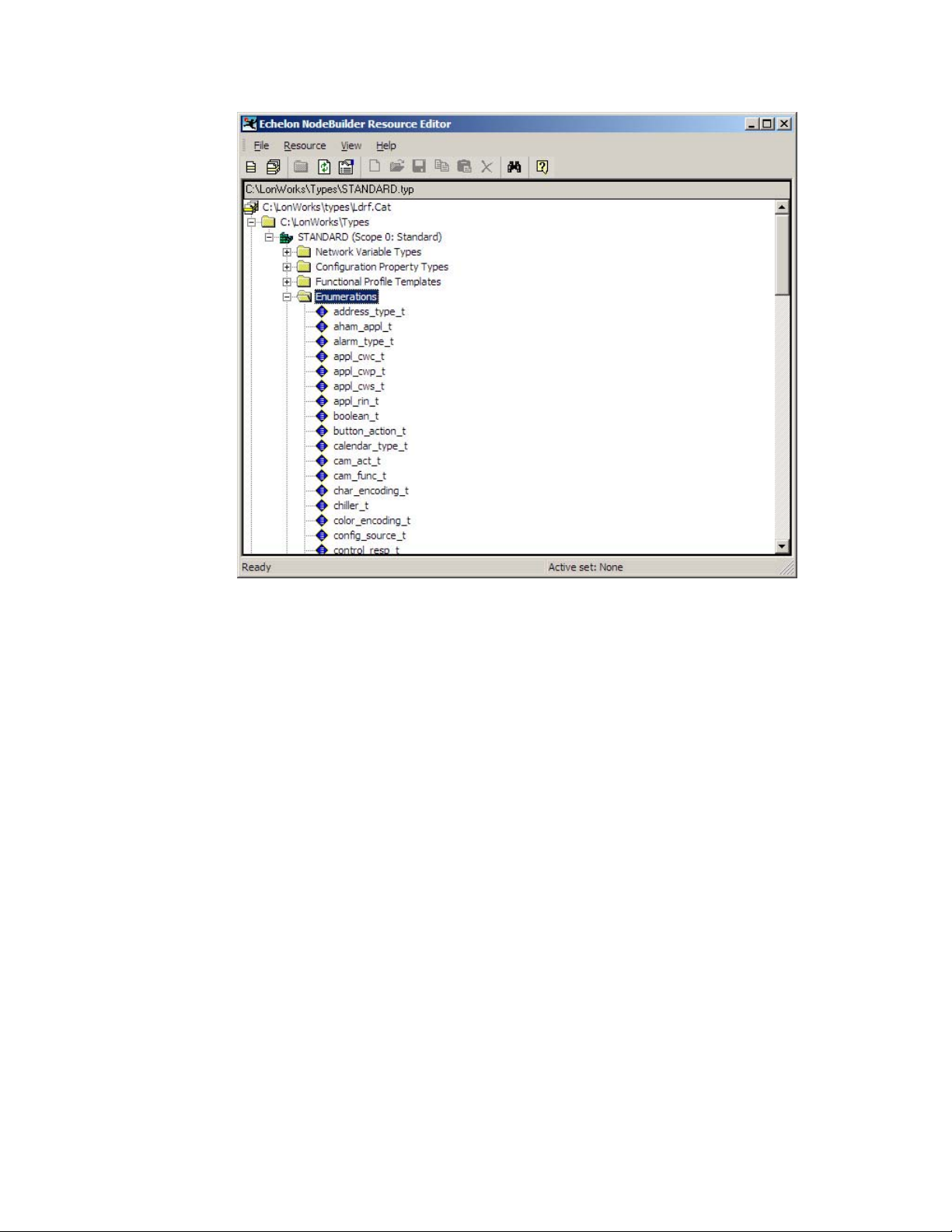
Figure 8. Enumerations within the NodeBuilder Resource Editor
Double-click the switch_state_t enumeration to display the enumeration values,
as shown in
Figure 9 on page 55.
54 LonBridge Device Class File
Page 61

Figure 9. The switch_state_t Enumeration
For the nviValue network variable, a LonBridge application uses the
SW_SET_OFF and SW_SET_ON values, which are enumeration values 0 and 1.
For the nvoValueFb network variable, a LonBridge application receives the
SW_REPORT_OFF and SW_REPORT_ON values, which are enumeration values
2 and 3.
state
Thus, the enumerations of the <nv> elements for the
device class file includes the following information:
<nv index="?" direction="input" size="3">
<byte index="0" length="1">
<attribute name="state" enum="true">
<enum input="off" output="0" />
<enum input="on" output="1" />
</attribute>
</byte>
<byte index="1" length="1">
<attribute name="state" enum="true">
<enum input="off" output="0" />
<enum input="on" output="200" />
</attribute>
</byte>
</nv>
attribute within the
LonBridge Server User’s Guide 55
Page 62

<nv index="?" direction="output">
<byte index="0">
<attribute name="state" enum="true" scale="100">
<enum input="2" output="off" />
<enum input="3" output="on" />
</attribute>
</byte>
</nv>
The next step is to fill in the missing network variable indices.
Browse the XIF File to Determine Indices
The LONWORKS device’s generated external device interface (XIF) file includes
the device’s self documentation, and thus includes all of the information that is
needed to connect to the device and manage the device within the network.
For creating a device class file, you only need the information about the network
variables, which appears near the beginning of an XIF file. The relevant part of
the XIF file for the simplified Lamp Module includes the following information:
VAR nviValue 0 0 0 0
0 1 63 0 0 1 0 1 0 0 0 0 0
"@0|1
189 * 3
1 0 0 1 0
4 0 1 0 0
1 0 0 0 0
VAR cpMinSendTime 1 0 0 0
0 1 63 0 0 1 0 1 0 0 0 0 1
"&2,2,0\x80,137
13 * 1
2 0 0 0 0
VAR nvoValueFb 2 0 0 0
0 1 63 1 0 1 0 1 0 0 0 0 0
"@0|2
189 * 3
1 0 0 1 0
4 0 1 0 0
1 0 0 0 0
VAR nvoOccupancyFb 3 0 0 0
0 1 63 1 0 1 0 1 0 0 0 0 0
"@0|3
109 * 1
1 0 0 1 0
VAR cpPwrSendOnDelta 4 0 0 0
0 1 63 0 0 1 0 1 0 0 0 0 1
"&2,5,0\x80,315
27 * 1
2 0 0 0 0
VAR nvoPower 5 0 0 0
0 1 63 1 0 1 0 1 0 0 0 0 0
"@0|4
27 * 1
2 0 0 0 0
VAR cpEnergyCntInit 6 0 0 0
0 1 63 0 0 1 0 1 0 0 0 0 1
"&2,7,0\xA4,137
13 * 1
2 0 0 0 0
VAR nvoEnergyHi 7 0 0 0
56 LonBridge Device Class File
Page 63

0 1 63 1 0 1 0 1 0 0 0 0 0
"@0|6
13 * 1
2 0 0 0 0
VAR nvoEnergyLo 8 0 0 0
0 1 63 1 0 1 0 1 0 0 0 0 0
"@0|10
14 * 1
2 0 0 0 0
VAR nvoMultiplierFb 9 0 0 0
0 1 63 1 0 1 0 1 0 0 0 0 0
"@0|7
188 * 1
1 0 0 0 0
VAR cpRunHrInit 10 0 0 0
0 1 63 0 0 1 0 1 0 0 0 0 1
"&2,11,0\xA4,135
87 * 5
2 0 0 0 0
1 0 0 0 0
1 0 0 0 0
1 0 0 0 0
2 0 0 0 0
VAR nvoRunHours 11 0 0 0
0 1 63 1 0 1 0 1 0 0 0 0 0
"@0|8
87 * 5
2 0 0 0 0
1 0 0 0 0
1 0 0 0 0
1 0 0 0 0
2 0 0 0 0
VAR nvoConnSize 12 0 0 0
0 1 63 1 0 1 0 1 0 0 0 0 0
*
8 * 1
2 0 0 0 0
Because the XIF file includes the network variable name as declared in the
Neuron C source files, you can match the definitions within the XIF file to the
declarations in the Neuron C files, as shown in
Table 13.
Table 13. Comparing Neuron C and XIF File Information
Neuron C Declaration XIF File Definition
network input SNVT_switch_2
nviValue;
VAR nviValue 0 0 0 0
0 1 63 0 0 1 0 1 0 0 0 0 0
"@0|1
189 * 3
1 0 0 1 0
4 0 1 0 0
1 0 0 0 0
LonBridge Server User’s Guide 57
Page 64

Neuron C Declaration XIF File Definition
network output polled SNVT_switch_2
nvoValueFb
nv_properties {
cpMinSendTime
};
network output polled SNVT_power
nvoPower
nv_properties {
cpPwrSendOnDelta
};
For a device class file, you need the network variable index for each network
variable. The index is the first value following the network variable name:
• VAR nviValue 0 0 0 0 …
• VAR nvoValueFb 2 0 0 0 …
• VAR nvoPower 5 0 0 0 …
VAR nvoValueFb 2 0 0 0
0 1 63 1 0 1 0 1 0 0 0 0 0
"@0|2
189 * 3
1 0 0 1 0
4 0 1 0 0
1 0 0 0 0
VAR nvoPower 5 0 0 0
0 1 63 1 0 1 0 1 0 0 0 0 0
"@0|4
27 * 1
2 0 0 0 0
Thus, nviValue has index 0, nvoValueFb has index 2, and nvoPower has index
5. And so, you can fill in these values within <attributes> element in the device
class file:
<attributes>
<attribute name="state">
<nvs>
<nv index="0" direction="input" />
<nv index="2" direction="output" />
</nvs>
</attribute>
<attribute name="power">
<nvs>
<nv index="5" direction="output" />
</nvs>
</attribute>
</attributes>
Likewise, you can you can fill in these values within <nvs> element in the device
class file:
<nvs>
<nv index="0" direction="input" size="3">
<byte index="0" length="1">
<attribute name="state" enum="true">
...
</attribute>
</byte>
</nv>
<nv index="2" direction="output">
58 LonBridge Device Class File
Page 65

<byte index="0">
<attribute name="state" enum="true">
...
</attribute>
</byte>
</nv>
<nv index="5" direction="output" size="2">
<byte index="0">
<attribute name="power" length="2" />
</byte>
</nv>
</nvs>
The next step is to ensure that the device class file is complete, and is not missing
any important information.
Complete Device Class File
After completing the steps described in the previous sections, the simplified
Lamp Module should have the following device class file:
<device pid="9FFFFF1E284A1101" name="Simple Lamp Module"
type="simple" brand="Test">
<attributes>
<attribute name="state">
<nvs>
<nv index="0" direction="input" />
<nv index="2" direction="output" />
</nvs>
</attribute>
<attribute name="power">
<nvs>
<nv index="5" direction="output" />
</nvs>
</attribute>
</attributes>
<nvs>
<nv index="0" direction="input" size="3">
<byte index="0" length="1">
<attribute name="state" enum="true">
<enum input="off" output="0" />
<enum input="on" output="1" />
</attribute>
</byte>
<byte index="1" length="1">
<attribute name="state" enum="true">
<enum input="off" output="0" />
<enum input="on" output="200" />
</attribute>
</byte>
</nv>
<nv index="2" direction="output">
<byte index="0">
<attribute name="state" enum="true" scale="100">
<enum input="2" output="off" />
<enum input="3" output="on" />
</attribute>
LonBridge Server User’s Guide 59
Page 66

</byte>
</nv>
<nv index="5" direction="output" size="2">
<byte index="0">
<attribute name="power" scale="10" length="2" />
</byte>
</nv>
</nvs>
</device>
60 LonBridge Device Class File
Page 67

www.echelon.com
 Loading...