

Page 1

LNS DDE Server
User’s Guide
Version 2.11
@
eCHELON
C o r p o r a t i o n
078-0170-01D
Page 2

Echelon, LON, LONWORKS, LNS, LonTalk, Neuron, LONMARK, 3120, 3150, the
LonUsers logo, the Echelon logo, and the LONMARK logo are registered
trademarks of Echelon Corporation. LonPoint, LonMaker, and LonSupport
are trademarks of Echelon Corporation.
Other brand and product names are trademarks or registered trademarks
of their respective holders.
Smart Transceivers, Neuron
Chips, LonPoint Modules, and other OEM
Products were not designed for use in equipment or systems which involve
danger to human health or safety or a risk of property damage and
Echelon assumes no responsibility or liability for use of the Neuron
Chips or
LonPoint Modules in such applications.
Parts manufactured by vendors other than Echelon and referenced in this
document have been described for illustrative purposes only, and may not
have been tested by Echelon. It is the responsibility of the customer to
determine the suitability of these parts for each application.
ECHELON MAKES AND YOU RECEIVE NO WARRANTIES OR CONDITIONS,
EXPRESS, IMPLIED, STATUTORY OR IN ANY COMMUNICATION WITH YOU, AND
ECHELON SPECIFICALLY DISCLAIMS ANY IMPLIED WARRANTY OF
MERCHANTABILITY OR FITNESS FOR A PARTICULAR PURPOSE.
No part of this publication may be reproduced, stored in a retrieval system,
or transmitted, in any form or by any means, electronic, mechanical,
photocopying, recording, or otherwise, without the prior written permission
of Echelon Corporation.
Printed in the United States of America.
Copyright © 1998-2002 by Echelon Corporation.
Model Number 39520
Echelon Corporation
550 Meridian Ave.
San Jose, CA 95126, USA
Page 3

Contents
1 LNS DDE Server Overview 1-1
New Feature in Release 2.11 1-2
New Features in Release 2.1 1-2
Overview of L
Installing of a LONWORKS Network 1-3
Monitoring and Controlling a LONWORKS Network 1-3
Network Variables 1-3
Configuration Properties 1-4
L
ONMARK® Objects 1-5
Application and Foreign Frame Messages 1-5
The Role of the LNS DDE Server 1-5
The Role of the LNS Network Interface 1-6
Overview of DDE 1-6
Types of DDE Services 1-7
Execute Commands 1-7
2 Getting Started 2-1
Requirements 2-2
Installing the LNS DDE Server 2-2
Installing and Configuring a Network Driver 2-6
Starting the LNS DDE Server 2-6
Using the LNS DDE Server 2-7
Folder Pane 2-7
Detail Pane 2-8
Log Pane 2-8
Menu Bar 2-9
Toolbar 2-10
Using the LNS DDE Server Examples 2-11
Using the Example LNS Database 2-11
Sequence of Operation 2-13
Using the LNS DDE Example Database 2-13
Using the Excel Example 2-14
Using the InTouch Example 2-15
3 Configuring the LNS DDE Server 3-1
Configuration Overview 3-2
Server Settings 3-2
DDE Server Settings 3-3
Application Name 3-3
Register DDE Share Name 3-3
NetDDE Being Used 3-3
Network Server 3-4
Response Timeout (sec) 3-4
Idle Timeout (sec) 3-4
ONWORKS® Networks 1-3
LNS DDE Server User’s Guide iii
Page 4

Service 3-4
Run as a Windows NT Service 3-4
Write Messages to the Event Log 3-5
Message Logging Settings 3-6
Display Information Messages 3-6
Display Warning Messages 3-6
Display Error Messages 3-6
Display Trace Messages 3-6
Max Number of Lines 3-6
Scrolling Rate (ms) 3-6
Circular Log File 3-6
Max Log File Size 3-7
Log to WWLogger 3-7
LNS Object Server Settings 3-7
Format and Typefile Catalog Path Setting 3-7
Global Database Path Setting 3-8
Remote Settings 3-8
Remote Operation 3-8
Network Interface 3-9
Database Settings 3-9
Single User Mode 3-9
Trace Options 3-9
DDE Toolkit 3-10
Client Connection 3-10
Client Disconnection 3-10
Point Creation 3-10
Point Activation 3-11
Point Updating 3-11
Point Poking 3-11
Point Deactivation 3-11
Point Deletion 3-11
Execute 3-11
Formatting 3-11
Format Files 3-12
Type Files 3-12
Format Errors 3-12
Format Use 3-12
Format Search 3-12
Network Server 3-12
Launching 3-13
LNS Errors 3-13
Flow Control 3-13
Events 3-13
Update Errors 3-13
Service Pins 3-13
Attachments 3-14
Database Changes 3-14
License Settings 3-14
Current License 3-15
License Type 3-15
Restriction 3-15
iv Table of Contents
Page 5

Serial Number 3-16
Generate PC Key 3-16
Creating an Unlimited Mode License 3-16
Transferring Licenses 3-18
Network Settings 3-18
Network Name 3-19
Database Path 3-19
Authentication Key 3-20
Network Interface 3-20
Network Attached 3-20
Network Interface Name 3-20
Attach to Network when Exploring 3-20
Set Management Mode OnNet 3-20
Network Event Subscription 3-21
Default Data Reporting Settings 3-21
Polling Interval (1/10 sec) 3-21
Refresh Rate (1/10 sec) 3-22
Use Bound Updates 3-22
Use Priority Messages 3-24
Number of Retries 3-24
Reply Timeout (1/10 sec) 3-24
Exclusive Mode (TCP/IP) 3-25
Host Message Owner 3-25
Point Recovery Strategy 3-25
Message Options—Network Variables 3-25
Service 3-25
Bound Service 3-25
Bound Update Persistent 3-26
Message Options—Application Messages 3-26
Service 3-26
Authenticate Messages 3-26
Include Sequence Message 3-26
Creating Custom Topics 3-26
Topic Name 3-27
Network 3-27
Subsystem 3-27
Update Interval 3-27
4 Addressing DDE Messages 4-1
Address Components 4-2
Topics 4-2
Standard Topic Format 4-3
Custom Topic Format 4-4
Topic Types 4-4
Topic Types and the Folder Pane 4-6
Items 4-7
LNS DDE Server User’s Guide v
Page 6

5 Reading and Writing Network Variables 5-1
Specifying a Network Variable 5-2
Specifying a Network Variable Topic 5-2
Specifying a Network Variable Item 5-2
Network Variable Formats 5-5
Requesting a One-Time Network Variable Update 5-6
Requesting a One-Time Network Variable Update Using Excel 5-6
Requesting a One-Time Network Variable Update Using InTouch 5-8
Receiving Ongoing Network Variable Updates 5-9
Event Driven Updates versus Polling 5-9
Monitoring Polled Output Network Variables 5-10
Receiving Ongoing Updates Using Excel 5-10
Receiving Ongoing Updates Using InTouch 5-11
Sending a Network Variable Update 5-11
Sending a Network Variable Update Using Excel 5-12
Sending a Network Variable Update Using InTouch 5-13
Timing Issues Related to Visual Basic Controls 5-14
6 Reading and Writing Configuration Properties 6-1
Specifying a Configuration Property 6-2
Specifying a Configuration Property Topic 6-2
Specifying a Configuration Property Item 6-2
Accessing Configuration Property User Formats 6-4
Requesting a One-Time Configuration Property Update 6-5
Receiving Ongoing Configuration Property Updates 6-6
Sending a Configuration Property Update 6-6
7 Receiving and Sending Application and Foreign
Frame Messages 7-1
Specifying an Incoming Message Item 7-2
Specifying a Request Message 7-3
Specifying a Message Completion Event 7-5
Specifying an Outgoing Application Message 7-7
Specifying a Message Using Domain-Wide Broadcast Addressing 7-8
Requesting a One-Time Update 7-10
Requesting Ongoing Message Updates 7-11
Sending a Message Update 7-11
8 Using Properties 8-1
Properties 8-2
Specifying a Property 8-2
System Properties 8-2
Device and Router Properties 8-3
Properties Available in both Application Devices and Routers 8-4
Properties Available only in Application Devices 8-6
Properties Available in both Application Devices
and in each side of Routers (NearSide and FarSide) 8-6
L
ONMARK Object Properties 8-7
vi Table of Contents
Page 7

Point Properties 8-8
Appendix A Resource Files A-1
LONMARK Resource Files A-2
Type File A-2
Format File A-3
Alternate Formats A-3
Language File A-4
Functional Profile Template File A-4
Appendix B Installing the PCLTA-10/20 and
PCC-10 Drivers B-1
PCLTA-10, PCLTA-20, and PCC-10 Adapter Installation B-2
PCLTA-10, PCLTA-20, and PCC-10 Software Installation Procedure B-2
Hardware Installation Procedure B-4
PCLTA-10 Adapter Hardware Installation Procedure B-4
PCLTA-20 Adapter Hardware Installation Procedure B-5
PCC-10 Card Hardware Installation Procedure B-5
PCLTA-10, PCLTA-20, and PCC-10 Diagnostic Procedure B-6
Appendix C WonderWare InTouch Client Example C-1
Introduction C-2
InTouch Overview C-2
InTouch Example Tutorial C-3
InTouch Animation and I/O Tags C-3
Network Variable Monitoring C-8
Changing the Default Format C-10
Display Unit Conversion C-10
Using the InTouch DDE Link Wizards C-11
Other Topic Types C-14
Appendix D License Order Form D-1
Appendix E LNS DDE Server
Software License Agreement E-1
Notice E-2
LNS DDE Server Software License Agreement E-2
License E-2
Limited Warranty and Disclaimer E-4
Limitation of Liability E-4
Safe Operation E-4
Language E-5
General E-5
Appendix F LNS DDE Server Software
License Transfer Agreement F-1
Glossary Gl-1
LNS DDE Server User’s Guide vii
Page 8

viii Table of Contents
Page 9

1
LNS DDE Server Overview
This chapter defines the main concepts for a LONWORKS® network, the
role of a network management tool in setting up a network, and the
role of the LNS DDE Server in monitoring and controlling the
network. It also provides a brief overview of DDE and a summary of
the new features in Releases 2.1 and 2.11. Additional terms are
defined in the Glossary.
LNS DDE Server User's Guide 1-1
Page 10

New Features in Release 2.11
Release 2.l1 (release 2.1 with Service Pack 1 applied) of the LNS DDE Server
includes adds date stamping to the log pane.
New Features in Release 2.1
Release 2.1 of the LNS DDE Server includes the following new features:
• Expanded Polling Capability - When used with either an LNS fast network
interface attached to a LonWorks channel, or an IP network interface attached to
a LonWorks/IP channel, the LNS DDE Server can now poll up to 1,000 points
simultaneously, instead of the maximum of 2 in the previous release. The result
is a significant improvement in the number of points per second that may be
polled.
• Expanded Binding Capability - When used with either an LNS fast network
interface attached to a LonWorks channel, or an IP network interface attached to
a LonWorks/IP channel, the LNS DDE Server now has an address table with
32,768 entries instead of the 16 entries in the previous release. This enables the
LNS DDE Server PC to be a member of every group within a domain, eliminating
many of the binding constraints of the previous release, and supporting many
more bound connections.
• LNS 3 Runtime - Release 2.1 of the LNS DDE Server installs the LNS 3
Runtime. This provides significantly improved performance when using either
an LNS fast network interface attached to a LonWorks channel, or an IP network
interface attached to a LonWorks/IP channel. The performance improvements
are a result of faster throughput through the LNS runtime and the network
interface, and the increased capacities for polling and binding.
• LonWorks/IP Channel Support - Release 2.1 of the LNS DDE Server can be used
to monitor and control remote full client networks over a LonWorks/IP Channel.
This allows the LNS Server PC to be attached directly to an IP channel without
requiring an LNS network interface card. This also increases performance for
most monitoring and control applications. For example, an application that
could previously poll no more than 35 points per second may be able to poll over
600 points per second from a LonWorks/IP client. A LonWorks/IP client can
receive over 1200 updates per second for bound updates. Actual performance
depends on your computer hardware and application.
• Wonderware SuiteLink Support -- The Wonderware SuiteLink protocol is now
supported for accessing the LNS DDE Server, in addition to the Microsoft DDE
protocol. This provides improved performance for Wonderware InTouch clients.
• Multiple Network Support - A single instance of the LNS DDE Server can now
simultaneously open up to 100 LNS networks through a single LNS network
interface. This includes both local and remote networks. This allows a single
DDE application to provide an interface to multiple networks, either through a
1-2 LNS DDE Server Overview
Page 11

single network interface, or through multiple network interfaces. To open
multiple remote networks, you must configure the LNS DDE Server as a
lightweight client. See Remote Settings in Chapter 3, Using the LNS DDE
Server.
• Updated Network Drivers - New drivers are included for the PCC-10, PCLTA-10,
and PCLTA-20 cards. These new drivers include new firmware for the network
interface cards that reconfigures the cards as LNS fast network interfaces,
providing significant performance improvements for LNS DDE Server
applications.
• Service Mode Operation - It is now easier to run the LNS DDE Server as a
Windows XP, Windows 2000, or Windows NT system service. This allows the
LNS DDE Server to continue operating even as operators log out of and log onto a
Windows XP, Windows 2000, or Windows NT computer. When running as a
system service, the LNS DDE Server may be configured to interact with the user
desktop, providing an easy-to-use interface for operators to view all points
available to the LNS DDE Server. Alternatively, the LNS DDE Server may be
configured to run hidden, preventing access by operators.
Overview of LONWORKS Networks
A LONWORKS network consists of intelligent devices, also called nodes, connected by
one or more communications channels that communicate with one another using the
LONWORKS protocol. LONWORKS devices are programmed to send messages to one
another in response to external events or messages that they receive. Two devices do
not have to be attached to the same physical communications channel to
communicate; however, they must be part of the same network. A network consists of
all of the devices that can exchange LONWORKS messages, and the communications
channels and routers that allow the devices to communicate.
Installing a LONWORKS Network
Before the LNS DDE Server can monitor and control a network, the network must be
installed using an LNS installation tool such as the LonMaker™ Integration Tool.
Installation of a control network is the process of loading the unique network
personality of each device into its internal tables. This process enables each device
to communicate with other devices in the same system. Maintenance involves tasks
such as adding new devices, replacing failed devices, and re-configuring the devices
that share data with one another.
As the installation tool configures the devices on the network, it stores a copy of this
information in the LNS Server. When installation is complete, the LNS Server
contains a picture of the configuration of the entire network along with the names of
all the devices and the network variables, configuration properties, and L
objects (also called functional blocks) on the devices. The LNS DDE Server uses the
information in the LNS Server to accomplish its tasks.
LNS DDE Server User's Guide 1-3
ONMARK
Page 12

Monitoring and Controlling a LONWORKS Network
Due to their high reliability, low cost, and flexibility, LONWORKS networks are used
in many ways. For example, they can be used to instrument relay-controlled
systems, saving the time, complexity, and cost associated with running wire from
each point back to the monitoring station. They can also be used in conjunction with
a central controller or PLC, for example, to provide a subsystem of smart sensors.
L
ONWORKS networks are frequently used to create peer-to-peer systems where each
device controls its own actions and shares information with its neighbors as needed
to control the entire system.
When monitoring a L
directly from a device, since each device is intelligent and knows its own status.
Similarly, when controlling a LONWORKS network, a control device can send data
directly to a controlled device. No master needs to be involved and no additional
wires need to be run. Also, using the information in the LNS Server, devices can be
addressed by the names assigned during installation. These names are much easier
to remember than the complex addressing schemes used by hard-wired systems, and,
since they are assigned in lock-step with the installation, they match what is
actually contained in the system.
There are several methods for exchanging data between L
are network variables, configuration properties, and application and foreign frame
messages. These are described in the following sections. LONMARK objects are also
described since they provide a higher-level description of the interfaces to a device.
ONWORKS network, the monitoring system can request status
ONWORKS devices. These
Network Variables
The most common way for LONWORKS devices to communicate with one another is
through network variables. Network variables are the logical inputs and outputs of a
device. The types, functions, and number of network variables in each device are
determined by the application code within the device. For example, a temperature
sensor might have two network variables — a temperature reading output and an
over-temperature alarm output. Some devices may also support dynamic network
variables that can be added and deleted by an LNS network tool such as the
LonMaker Integration tool. The host PC running the LNS DDE Server also supports
dynamic network variables.
The actual data representation of a network variable is defined by its type. The type
may either be a user defined network variable type (UNVT), or a standard network
variable type (SNVT). SNVTs ensure common data representation and
interoperation for all LONWORKS devices; using SNVTs is recommended whenever
possible. A master list of standard network variable types is contained in the LNS
Utilities and LonMark Reference help file included with the LNS DDE Server.
Configuration Properties
Application configuration data is specified using configuration properties.
Configuration properties may be implemented on a device as configuration network
variables or as configuration parameters. Any device can use configuration network
variables. Devices that comply with the LONMARK Application Layer
Interoperability Guidelines, version 3.0 or later, may use configuration parameters.
1-4 LNS DDE Server Overview
Page 13

Configuration parameters are stored in files on the device, and may be accessed
using the LONWORKS file transfer protocol, or by direct memory read/write for
Neuron Chip hosted devices. Configuration properties may be properties of the
device, a LONMARK object, or a network variable.
The data representation and interpretation of a configuration property is defined by
its type. The type may either be a user defined configuration property type (UCPT),
or a standard configuration property type (SCPT). SCPTs are a standard in all
ONWORKS devices; using SCPTs is recommended whenever possible. A master list
L
of standard configuration property types is contained in the LNS Utilities and
LonMark Reference help file included with the LNS DDE Server.
LONMARK Objects
LONMARK objects are collections of associated network variables and configuration
properties along with definitions of their associated behavior. LONMARK objects
provide the basis for application layer interoperability.
The network variable and configuration property members of a LONMARK object,
along with the interpretation of each, are defined by functional profiles. The
functional profile may either be a user defined functional profile, or a standard
functional profile. Standard functional profiles are defined and maintained by the
LONMARK Interoperability Association.
Application and Foreign Frame Messages
Application and foreign frame messages are a low-level method of exchanging data
between L
message code for identification. The message code identifies the message as a
network variable, application, foreign frame, network management, or network
diagnostic message. Network variable and application messages are used for
exchanging application data. Foreign frame messages are used by gateway
applications. Network management and network diagnostic messages are used by
the LNS Server. Application and foreign frame messages are less interoperable than
network variables because all devices that need to share information must be
designed with their message codes in agreement. The message codes are part of the
application program and are not configurable.
Devices send and receive application and foreign frame messages using message tags.
A message tag is an input or output port of a device. A device can send a message
with any message code using any of its message tags. Similarly, a message with any
code might arrive at any of the device's message tags. Establishing connections
between device message tags is another task done by an LNS network tool during
network installation.
ONWORKS devices. Each LONWORKS message must be given a unique
The Role of the LNS DDE Server
The LNS DDE Server exchanges network variable, configuration property, and
application and foreign frame message data between LONWORKS devices and
Windows applications. With the LNS DDE Server, any Windows application that
can act as a DDE Client can monitor and control one or more LONWORKS networks.
LNS DDE Server User's Guide 1-5
Page 14

That is, the application can observe the values of network variables, configuration
properties, and application and foreign frame messages, and can change the values
of them to affect the operation of the network(s). The LNS DDE Server uses the
naming, addressing, and timing information stored in an LNS Server by a network
tool such as the LonMaker Integration Tool.
There are many tools available for installing LONWORKS networks. Some of these
are legacy tools that are not LNS compatible. However, the LNS DDE Server
requires that the network installation be completed using an LNS installation tool. If
you have a network that was installed with a network tool that was not based on
LNS, you can automatically convert the network to LNS using the LonMaker
Integration Tool, release 3.0 or later.
The Role of the LNS Network Interface
An LNS network interface (also called a network adapter, network services interface,
or NSI) is a hardware component with an associated network driver that provides
the physical connection between a LONWORKS network and the PC running the LNS
DDE Server. An LNS network interface is not required if your PC is running as a
remote L
client. For the highest performance for workstation applications on a desktop
attached to a LONWORKS/IP channel, you should use an IP network interface card
such as an Ethernet adapter. For the highest performance for workstation
applications on a desktop attached to a LONWORKS channel, you should use a
PCLTA-20 PCI LonTalk Adapter as the LNS network interface (use a PCLTA-10 ISA
LonTalk adapter if you do not have an available PCI slot). If you are using powerline
products or an SMX transceiver, you can use the PCLTA-20/SMX PCI card. If you
have a laptop attached to a LONWORKS channel with a PCMCIA-compatible PC Card
slot, you can use the PCC-10 PC Card interface. For connecting to a L
channel remotely via phone lines and a pair of modems, or if your host does not have
an available ISA, PCI, PC Card slot, you can use a SLTA-10 Serial LonTalk Adapter.
All PC-compatible LNS network interfaces are functionally equivalent; so your DDE
client application does not need to be modified when the LNS network interface
hardware changes. If you are not using a PCLTA-10, PCLTA-20, PCNSI, PCC-10,
SLTA-10, of IP network interface card, check your documentation to see if your
network interface is LNS-compatible.
ONWORKS /IP Remote, LNS/IP remote (i.e. Lightweight), or NetDDE remote
ONWORKS
Overview of DDE
Dynamic Data Exchange (DDE) defines a standard way for Microsoft Windows
applications to share information with one another. The following sections provide a
very brief overview of DDE.
When applications share information with each other using DDE, they are said to be
holding a DDE conversation. Each conversation has a well-defined beginning,
middle, and end. To begin a conversation, one application, known as the client, or
destination application, asks another application, known as the server, or source
application, to open a communications channel (this is different than a L
channel, which is the physical communications medium used by LONWORKS devices).
1-6 LNS DDE Server Overview
ONWORKS
Page 15

Once a conversation is established, the client can send and receive data from the
server on the DDE channel. For example, an Excel spreadsheet (the client) may ask
the LNS DDE Server (the server) for the current fuel consumption from a flow sensor
for use in an automated billing system. Or, an InTouch operator interface (the
client) may tell the LNS DDE Server (the server) to change the state of a valve in a
LONWORKS network in response to a request issued by the operator. The client
application is always the application that establishes the conversation, irrespective
of which way the data actually flows. The LNS DDE Server is always a server
application.
Types of DDE Services
A client uses different DDE services during the course of a DDE conversation. The
DDE services discussed in this manual are the following:
Initiate
Terminate
Request
Advise
Warm or
Poke
Execute
A request to start a new DDE conversation.
A request to end a DDE conversation.
A one-time request by the client for a specific piece of data
from the server. This is also referred to as a Cold or
Manual Link. The server does not notify the client of
changes; the server only sends the item's value when
requested by the client.
A request by the client for on-going updates for a specific
piece of data from the server. There are two types of Advise
requests.
Hot or
Automatic
Notify
A request from the client to the server to change the value
of a specific piece of data.
A request from the client to the server to perform a
command.
Whenever the value of the item changes, the
server automatically sends the client the
new value.
Whenever the value of the item changes, the
server sends the client notification that the
value has changed. If interested, the client
requests the new value from the server.
Note: The LNS DDE Server does not
support warm (notify) links.
Execute Commands
The LNS DDE Server provides the following commands via the DDE execute service.
These commands are not case sensitive.
LNS DDE Server User's Guide 1-7
Page 16

[Pause] Temporarily stops the LNS DDE Server from sending updates to
devices on the L
ONWORKS network, both updates to network
variables and network variable polls. When paused, however, it
will still receive network variable update messages from
application devices and pass those to the client.
[Resume] Reenables polling and outgoing update messages.
1-8 LNS DDE Server Overview
Page 17

2
Getting Started
This chapter explains how to install the LNS DDE Server, and how to
start it with an existing network.
LNS DDE Server User's Guide 2-1
Page 18

Requirements
The LNS DDE Server requires a PC that meets the following requirements:
• Microsoft Windows XP, Windows 2000, Windows Me, Windows 98, or Windows
NT 4.0 (Service Pack 3 or later is required for Windows NT; Windows XP or
Windows 2000 recommended)
• Pentium 133 or faster (Pentium 200 or better recommended)
• 20 Megabytes free hard-disk space
• 64 Megabytes of RAM minimum (128 Megabytes minimum recommended
• CD-ROM drive
• Mouse or compatible pointing device
Note: The memory required is affected by the number of Windows applications that
are running simultaneously. More than 64 Megabytes may be required if you are
running many applications at the same time.
The LNS DDE Server requires an LNS Server. The LNS Server may be on the same
PC or a remote PC. The LNS DDE Server is distributed with the required LNS
Server files.
Installing the LNS DDE Server
To install the LNS DDE Server, follow these steps:
1 If you are using Windows XP, Windows 2000, or Windows NT 4.0 and you do not
have Administrator privileges, log out of Windows, then log on as a user who is a
member of the Administrators group. Close all running Windows applications
and disable any virus checking utilities.
2 If your copy of the LNS DDE Server was delivered on a CD-ROM, insert the CD-
ROM into your CD-ROM drive. If the LNS DDE Server setup program does not
start automatically, open the Windows Start menu and select Run. Browse to
the Setup application on the LNS DDE Server CD and click Open, then click OK
to run the Setup program.
If you downloaded your copy of the LNS DDE Server, open the Windows Start
menu and select Run. Browse to the Setup application that you downloaded and
click Open, then click OK to run the Setup program.
The Setup program displays a series of dialogs that are described in the following
steps. Some of the dialogs may not be displayed depending on the choices you
make during installation. The first dialog is the Welcome dialog.
2-2 Installing the LNS DDE Software
Page 19
In the lower part of all the dialogs you will find navigation buttons. Use these
buttons to go forward to the next dialog, go back to the previous dialog, or cancel
the whole installation.
3 Click Next to continue with the next step. The License dialog is displayed.
4 Read the license in its entirety, and if you accept it, click I Agree. If you don’t
accept it click I Do Not Agree to terminate the installation without installing the
LNS DDE Server. If you accept the license agreement, the Registration dialog is
displayed.
5 Enter your name, company name, and LNS DDE Server serial number in the
appropriate fields. The serial number is located on your LNS DDE Server case
or envelope, or was provided to you when you downloaded the LNS DDE Server
software. It is not necessary to enter the serial number to install the software,
but when ordering an application key, a serial number must be supplied. Click
Next. The setup program displays the Select Components dialog.
LNS DDE Server User's Guide 2-3
Page 20
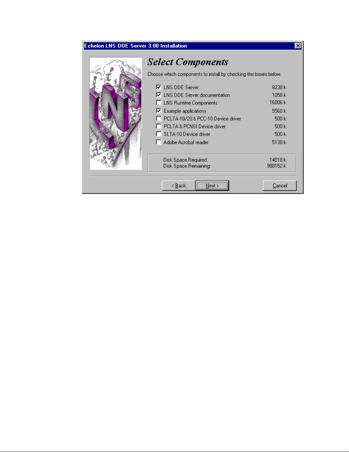
6 Select the LNS DDE Server components to be installed. The installation
program automatically preselects some of the components based in part on what
it finds already installed on your system. Some components may not be available
for installation. When selecting or clearing components, the disk usage for the
currently selected files is shown in the lower part of the window. Following is a
description of each of the options:
• LNS DDE Server. Installs the LNS DDE Server application files and creates
an Echelon LNS DDE Server program folder in your Windows Start menu.
This option must be installed to use the LNS DDE Server.
• LNS DDE Server documentation. Installs LNS DDE Server help file and an
Acrobat version of the LNS DDE Server User’s Guide.
• LNS Runtime Components. Installs the LNS network operating system
components required by the LNS DDE Server, including the LNS Server.
These components are required. The setup program will make a
determination of the proper setting of this option. This option also creates an
Echelon LNS Utilities program folder in your Windows Start menu.
• Example applications. Installs Excel and InTouch examples. See Using the
LNS DDE Server Examples for a description of the examples.
• PCLTA-10/20 & PCC-10, SLTA-10, and PCLTA & PCNSI device drivers.
Installs drivers required for accessing an LNS network interface. Select the
driver for the network interface hardware that you will be using on the PC
with the LNS DDE Server. A driver is not required if you are using the LNS
DDE Server as a L
• Adobe Acrobat reader. Installs the Adobe Acrobat reader that can be used to
read the Adobe Acrobat versions of the LNS DDE Server User’s Guide and
the PCC-10, PCLTA-10, PCLTA-20, SLTA-10, and PCNSI manuals.
ONWORKS/IP, LNS/IP, or NetDDE Client.
2-4 Installing the LNS DDE Software
Page 21

Select the components to be installed and click Next. The Select Destination
Directory window appears.
7 Choose a LONWORKS folder where you want the LNS DDE Server software
installed. The software will be installed in an LNSDDE folder below the
ONWORKS folder that you specify. If you have installed other LONWORKS
L
software on this computer, be sure to use the same LONWORKS folder. The
default folder is c:/LonWorks if you have not installed any other LONWORKS
applications; the default is the last LONWORKS folder that you used if you have.
Click Next. The Backup Replaced Files dialog is displayed.
8 The Backup dialog allows you to choose if you want to backup the LNS software.
The installation program includes an uninstaller which is capable of undoing all
changes and copying back the replaced files.
Warning! Backing up the software can lead to versioning issues under certain
circumstances after uninstalling the LNS DDE Server; always choose the default
not to back up the LNS software.
If you select the Yes option, the next dialog will allow you to select the folder
where the replaced files will be placed. Enter a folder and click Next. You may
receive a message stating Backup Already Exists Would You Like to Install that
Directory Anyway? Choose Yes or No.
9 After making all required selections, the next dialog declares that the Setup
program is ready to start installing the selected components. If you are unsure
about the selections you have made, you can take this opportunity to use the
Back button to review them. When you are sure everything is correct, press the
Next button to commence installation.
10 If the example applications were selected in step 6, the setup program for the
example applications will be started. Select the desired applications to install
and click Next. Enter a destination folder for the examples and click Next.
11 If any drivers were selected in step 6, the setup programs for the selected drivers
will start. Install the drivers as described in Installing and Configuring a
Network Driver.
12 If the Adobe Acrobat installation was selected in step 6, the Acrobat setup
program will start. Follow the instructions in the Acrobat setup dialog.
13 After the Setup program has completed, you may be prompted to restart your PC
to complete the installation. If prompted, restart the computer.
14 Download the latest LNS DDE Server service pack from
www.echelon.com/lonmaker. At the time of publication of this manual, the latest
service pack is LNS DDE Server 2.1 Service Pack 1. Follow the instructions
provided with the LNS DDE Server service pack to install it.
15 Reboot when instructed.
16 Download and install the latest LNS 3 service pack. At the time of publication of
this manual, the latest LNS 3 service pack was LNS 3 Service Pack 5A. You can
LNS DDE Server User's Guide 2-5
Page 22

download the latest LNS 3 service pack from www.echelon.com/lns. Follow the
instructions provided with the LNS service pack to install it.
17 If you selected a network driver in step 6, configure the network driver as
described in Installing and Configuring a Network Driver, later in this chapter.
If you have not installed an application key for the LNS DDE Server, the LNS DDE
Server will run for 30 days. After 30 days, it will continue to run for an hour at a
time until you acquire an Application key as described in Register Application Key in
Chapter 3.
Installing and Configuring a Network Driver
The LNS DDE Server may communicate with a LONWORKS network through an LNS
network driver and an LNS network interface or through an IP network driver and
an IP network interface. Supported LNS network interfaces are the i.LON 1000
Internet Server, PCLTA-10, PCLTA-20, PCC-10, PCNSI, and SLTA-10. The LNS
DDE Server Setup application includes drivers for these network interfaces (except
for the i.LON 1000 . The drivers can be installed at the same time as the LNS DDE
Server, or you may install them at a later time. It is not necessary to re-install the
network driver if you already configured it for use with the LonMaker Integration
Tool. Supported IP network interfaces include TCP/IP-compatible Ethernet adapters
and PPP dial-up interfaces.
If you have already installed a PCLTA-10, PCLTA-20, PCC-10, or PCNSI driver,
configure the driver. For the PCLTA-10, PCLTA-20, or PCC-10, be sure to install the
driver software before you install the network interface hardware. If you have
installed an SLTA-10 driver, configure the SLTA-10 hardware and driver as
described in the SLTA-10 User’s Guide, located in the SLTA-10 program folder. If
you are using an i.LON 1000, install the i.LON software as described in the i.LON
documentation. If you need to install a different driver, see the documentation for
that driver for installation instructions.
Starting the LNS DDE Server
As part of the installation process, the installation program will create a program
folder named Echelon LNS DDE Server and place a number of shortcuts in it. One of
the shortcuts points to the LNS DDE Server application. To access this folder, click
the Windows Start button, point to Programs, then click Echelon LNS DDE Server.
You can place a shortcut directly on your desktop, or you can make the LNS DDE
Server start automatically when you log on. To make the LNS DDE Server start up
automatically when you log on, copy the shortcut to your Windows Startup folder or,
if using Windows XP, Windows 2000, or Windows NT 4, you can configure the LNS
DDE Server to run as a service as described in Run as a Windows NT Service in
Chapter 3.
To start the LNS DDE Server, select the LNS DDE Server shortcut. When started,
the LNS DDE Server will display a window as described in the next section.
2-6 Installing the LNS DDE Software
Page 23
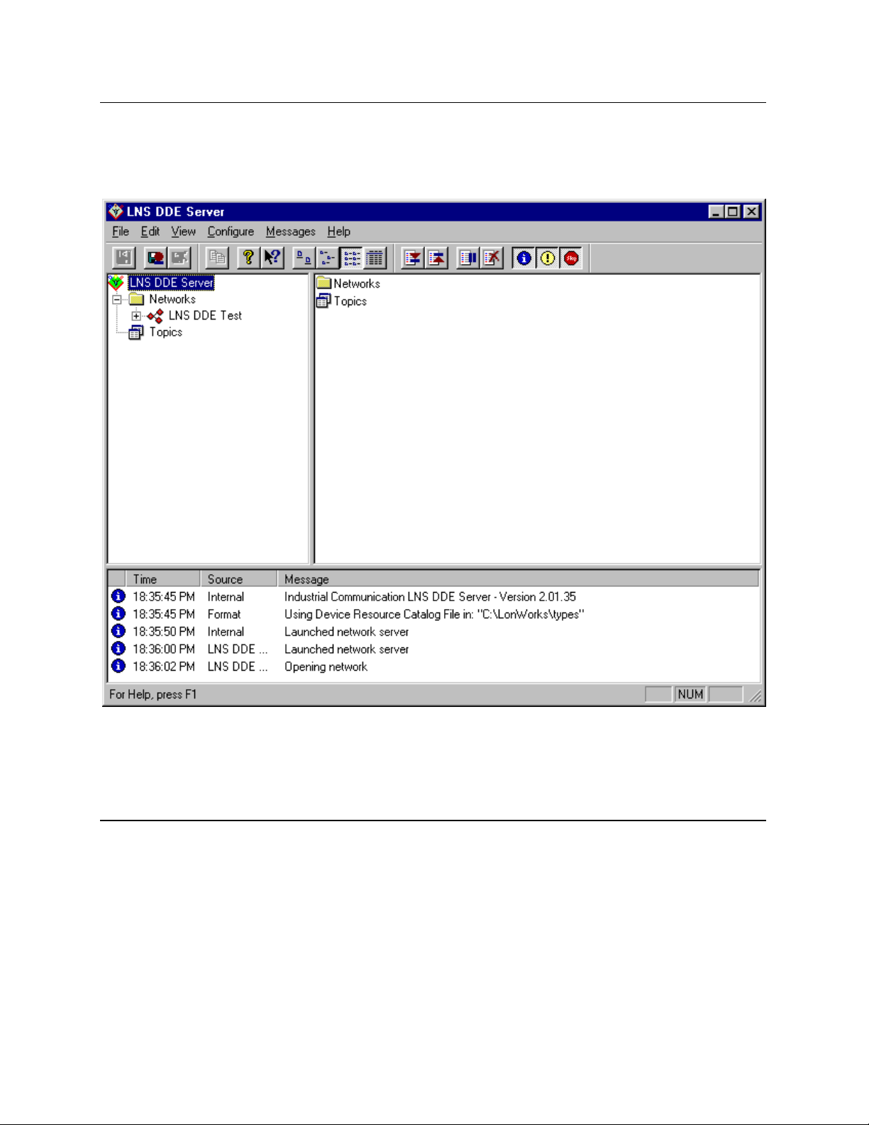
Using the LNS DDE Server
When you start the LNS DDE Server, a main window similar to the following figure
appears (you may see a different set of networks under the Networks folder and
different messages at the bottom of the screen):
The main window is divided into three panes. On the left side there is a folder pane,
on the right side there is a detail pane, and along the bottom a log pane. A menu bar
is displayed across the top. The three panes and the menu bar are described in the
following sections.
Folder Pane
The folder pane on the left side of the main window allows you to navigate the
networks, subsystems, devices, LONMARK objects, network variables, and
configuration properties that are defined in an LNS Server. The top-level of the
folder pane contains a Networks folder with all the currently available networks
listed, as well as a Topics folder with all the pre-created topics.
To view the subsystems, devices, L
configuration properties in a network, expand the Networks folder, then click the
network name in the folder pane. When you click a network name, the objects
LNS DDE Server User's Guide 2-7
ONMARK objects, network variables, and
Page 24

associated with the selected network will be listed in the detail pane on the right side
of the window. You can simultaneously open any number of the networks listed in
this pane.
Detail Pane
The detail pane lists the objects that are associated with the currently selected folder
on the folder pane. Depending on what type of folder is selected in the folder pane,
the detail pane may list the networks, subsystems, devices, L
network variables, configuration properties, or topics belonging to the currently
selected folder.
You can view the objects in the detail pane as large icons, small icons, or as a list
with details. To change currently selected view, right-click somewhere in the detail
pane and select a view from the shortcut menu, or select the desired view from the
View menu on the LNS DDE Server menu bar.
Log Pane
The log pane is displayed along the bottom of the LNS DDE Server main window.
The log pane shows messages generated by the LNS DDE Server.
The log messages may be caused by DDE client applications, the underlying LNS
software, or from internal activities in the LNS DDE Server. The log lists the
severity, date, time, source, and message text for each message.
You can filter the events shown in the log by selecting Messages/Log Display. The
selections made on the Log Display menu are temporary for the current session. To
configure more permanent filter settings, select the Server command from the
Configure menu on the menu bar. If messages are being logged to a file, the filter
settings you use in the Log Pane do not affect the messages logged to the file.
If you select the Trace option from Messages/Log Display, the messages displayed in
the Log Pane are controlled by the server configuration settings. See Trace Options
in Chapter 3 for more information on the Trace option.
Use the Page Up and Page Down keys to scroll the log, or use the scrollbar on the
right side of the pane. Right-click in the log pane and select the Top, Bottom, or
Clear commands to move to the top or bottom of the log, or to clear the contents of
the log. Alternatively, you can use the Go to Top, Go to Bottom, or Clear Log
commands on the View menu or these same commands on the Messages/Log Display
menu. You can stop automatically scrolling the log by selecting the Freeze command
from the Messages/Log Display menu.
The number of lines shown in the log is limited. To view or set the limit, select the
Server command from the Configure menu. The oldest lines will be removed from
the log when the limit is reached.
ONMARK objects,
2-8 Installing the LNS DDE Software
Page 25

Menu Bar
The menu bar contains six menus. These are described in the following table:
File
Save Log File Saves the contents of the log file.
Exit Terminates the LNS DDE Server.
Edit
Copy Link Copy link information for the currently selected object in the
View
Toolbars/Log File Toggles the display of the Log File toolbar, immediately below
Toolbars/Log Display Toggles the display of the Log Display toolbar, immediately
Toolbars/Miscellaneous Toggles the display of the Miscellaneous toolbar, immediately
Status Bar Toggles the display of the status bar at the bottom of the
Large Icons Changes icon view to large-sized icons.
Small Icons Reduces icon view to small-sized icons.
List Changes icon view in the detail pane to a list
Details Gives a description of each item in the Detail pane.
Go to Top Go to the top of the log.
Go to Bottom Go to the bottom of the log.
Clear Log Clears all log entries.
Refresh Refreshes the content of the folder and detail panes.
Configure
Server Opens a configuration dialog with tabs for the LNS DDE
Networks/
Configure All
Networks/
Import
Topics/
Configure All
Topics/
Create New
Topics/
Delete
Messages
Log Display/
Information
Log Display/
Warnings
folder or detail pane to the clipboard.
the menu bar on the left side.
below the menu bar on the right side.
below the menu bar in the center.
window.
Server Settings, the LNS Object Server, Trace Options, and
the LNS DDE Server License Settings.
Opens a configuration dialog with a tab for each network
defined in the LNS Server (up to 50 networks).
Opens a configuration dialog on which you can name a
network you want to import and configure the settings of that
network.
Opens a configuration dialog with a tab for each custom topic.
Creates a new custom topic.
Deletes a custom topic.
Toggles displaying of information events.
Toggles displaying of warning events.
LNS DDE Server User's Guide 2-9
Page 26
Log Display/
Errors
Log Display/
Trace
Log Display/
Freeze
Log Display/
Go to Top
Log Display/
Go to Bottom
Log Display/
Clear
Log File/
Log to File
Log File/
Clear
Log to WWLogger Toggles sending log messages to the Wonderware
Toggles displaying of error events.
Activates the tracing option.
Stops automatic scrolling of the log.
Go to the top of the log.
Go to the bottom of the log.
Clear the contents of the log.
When enabled causes all log and trace messages to be
written to a file on disk.
Clears the active log file. Enabled only when there are
messages present in the log file.
WWLogger logging application. (if available)
Help
Help Topics Opens the LNS DDE Server help file.
About LNS… Opens the About dialog.
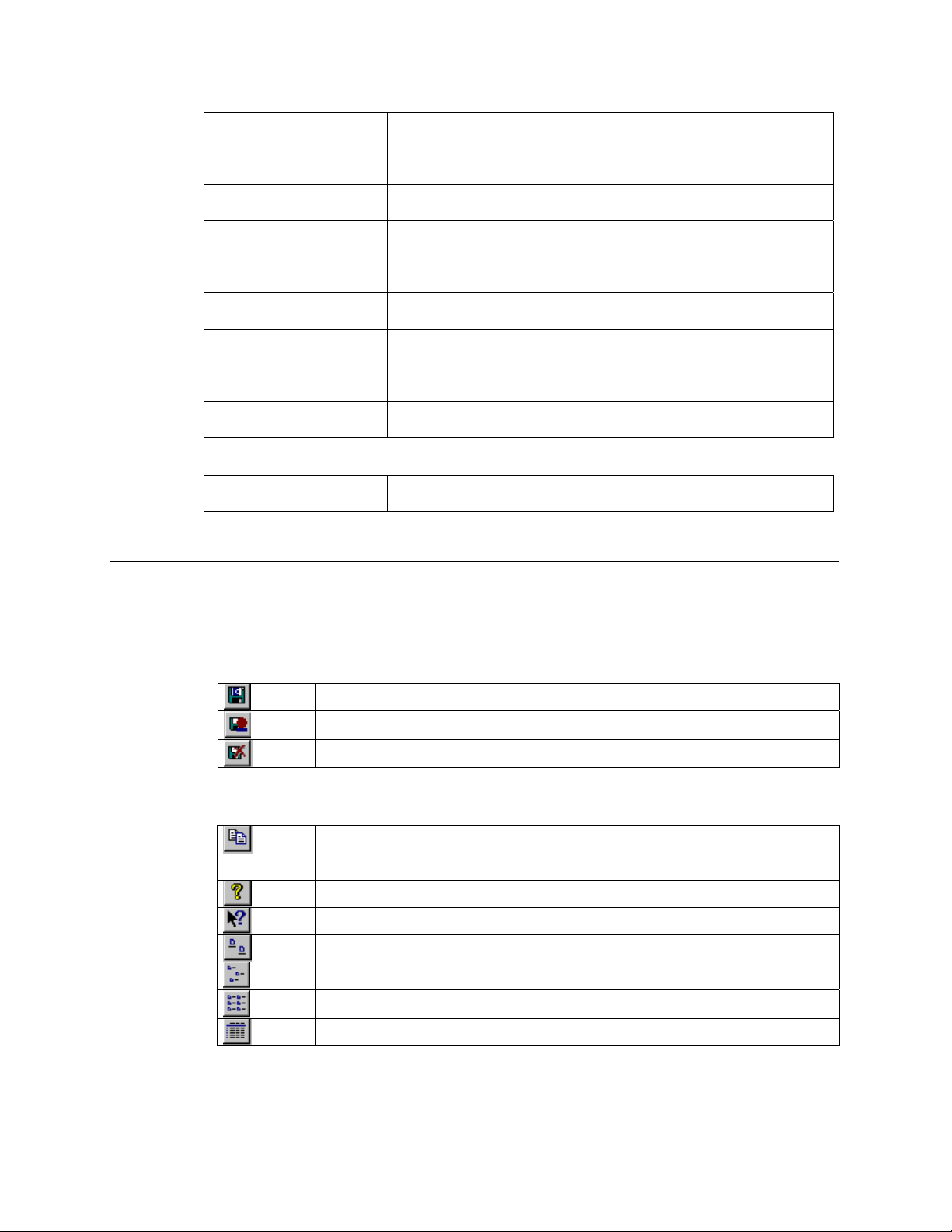
Toolbar
There are three toolbars: Log File, Log Display, and Miscellaneous. These toolbars
contain buttons that activate certain menu options with a single mouse click.
Log File
Save Log File Saves the current contents of the logfile.
Log to File Logs messages to a file.
Clear Log File Clears the active logfile.
Miscellaneous
Copy Link Copy link information for the currently selected
object in the folder or detail pane to the
clipboard.
About Opens the About dialog.
Help Opens the online help file.
Large Icons Presents the icons in large-sized format.
Small Icons Presents the icons in small-sized format.
List Presents the log in a list format.
Details Provides a description of log listings.
Log Display
2-10 Installing the LNS DDE Software
Page 27
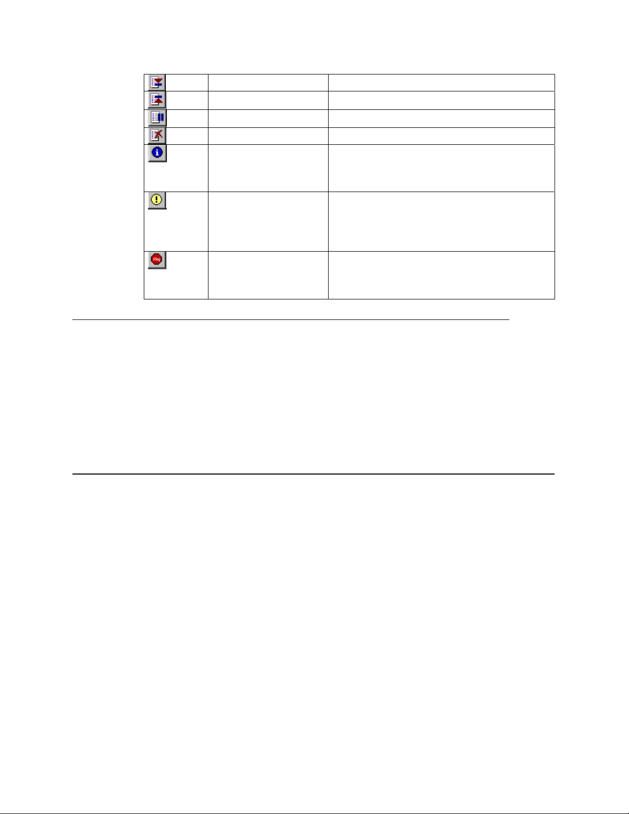
Bottom of Log Scrolls to the bottom of the log.
Top of Log Scrolls to the top of the log.
Freeze Stops automatic scrolling of the log.
Clear Message Display Clears the log display.
Display Information This setting controls filtering of information
messages for the log. Click this setting to
display information messages in the log. The
default setting is On.
Display Warnings This setting controls filtering of warning
messages for the log. Click this setting to
display warning messages in the log pane.
This setting should always be enabled. The
default setting is On.
Display Errors This setting controls error message filtering for
the log. Click this setting to display error
messages in the log pane. This setting should
always be enabled. The default setting is On.
Using the LNS DDE Server Examples
Two example applications are provided with the LNS DDE Server. They are an
Excel 97 spreadsheet and an InTouch 7.0 application. These examples are installed
if you select the Example applications option during the LNS DDE Server
installation procedure. You can rerun the LNS DDE Server installation program and
select the Example applications option if you did not initially install the
examples.
Many of the examples in this guide come from these two examples.
Using the Example LNS Database
The LNS database for both examples was created using the LonMaker Integration
Tool. Two LonMaker backup files are provided: LNS DDE Test V2.zip and LNS
DDE Test V3.zip in the LNSDde folder. These backup files each contain a
LonMaker drawing and an LNS database for use with the Excel and InTouch
examples. LNS DDE Test V2.zip contains a LonMaker database and drawing with
version 2 LonPoint applications. LNS DDE Test V3.zip contains a LonMaker
database and drawing with version 3 LonPoint applications. The following figure is
the LonMaker drawing for the LNS DDE Test example.
LNS DDE Server User's Guide 2-11
Page 28
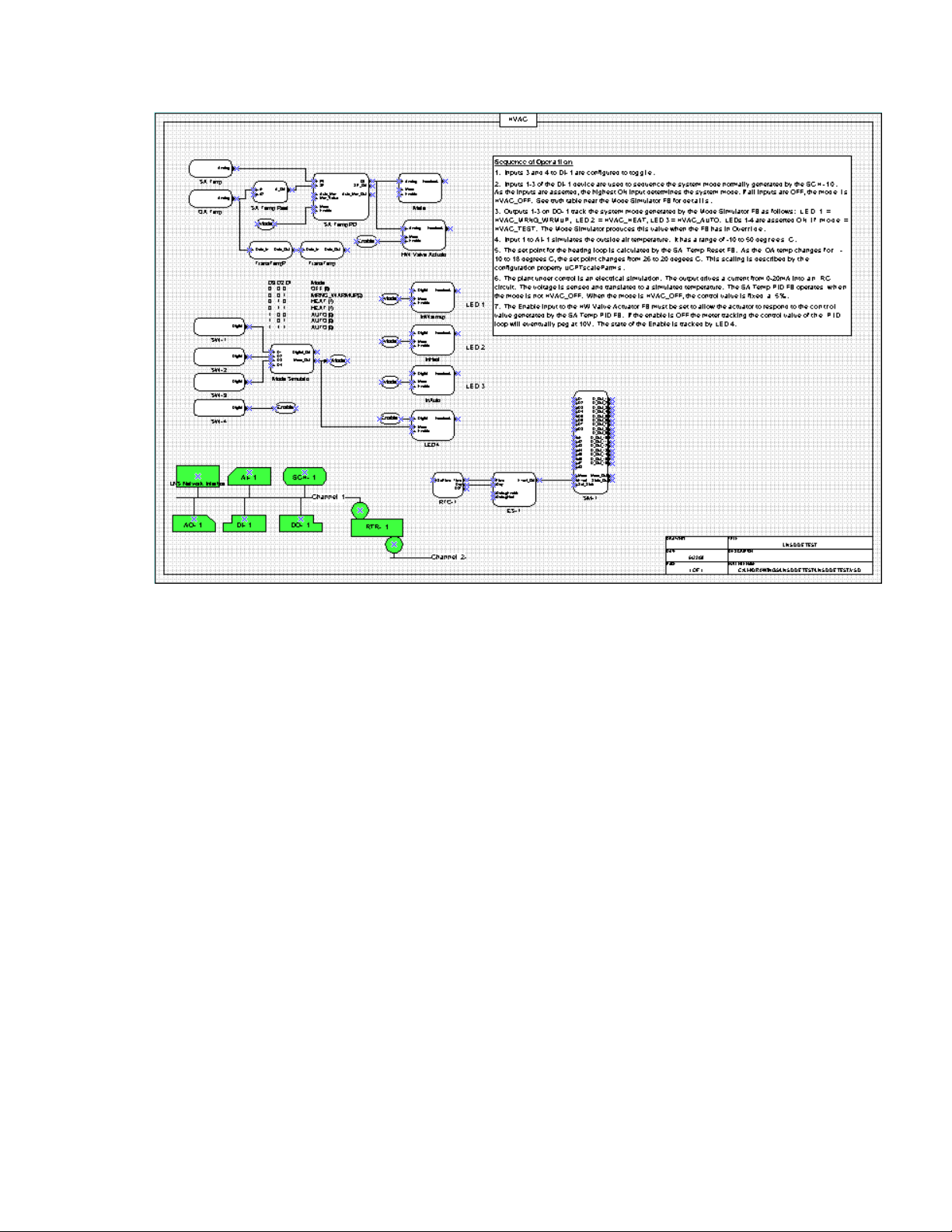
The LNS DDE Test example includes 5 application devices and a router, which
matches the hardware in a LonPoint Demo Kit. If you do not have LonPoint devices
to use with the examples, you can still open the examples in engineered mode to see
Excel and InTouch usage examples for the LNS DDE Server.
Following is a list of the 5 application devices defined in the LNS DDE Test example:
• AI- 1. A LonPoint AI-10 Analog Input Interface Module. Used to monitor a
simulated temperature and a temperature setpoint dial.
• AO- 1. A LonPoint AO-10 Analog Output Interface Module. Used to control a
simulated hot water valve actuator, and an analog meter monitoring the input to
the valve.
• DI- 1. A LonPoint DI-10 Digital Input Interface Module. Used to monitor 4 input
switches. Three of the switches are used to control the system mode, simulating
the output of a system mode generator. The fourth switch is used as a system
enable.
• DO- 1. A LonPoint DO-10 Digital Output Interface Module. Used to control 4
LEDs. Three of the LEDs are used to display the system mode. The fourth LED
is used to display the system enable status.
• SCH-1. A LonPoint SCH-10 Scheduler Module. This device is not used in the
example. Its operation is simulated by the mode simulator on the DI- 1 device.
These five devices contain L
ONMARK objects that are shown as functional blocks on
the LonMaker drawing. Each functional block has network variable inputs and
outputs that are shown as triangles on the functional blocks. These network
2-12 Installing the LNS DDE Software
Page 29

variables are connected as shown on the LonMaker drawing. The following list
summarizes the Sequence of Operations for the LNS DDE Test example.
Sequence of Operation
1. Inputs 3 and 4 to DI- 1 are configured to toggle.
2. Inputs 1-3 of the DI- 1 device are used to sequence the system mode normally
generated by the SCH-10. As the inputs are asserted, the highest ON input
determines the system mode. If all inputs are OFF, the mode is HVAC_OFF. See
the truth table near the Mode Simulator functional block for details.
3. Outputs 1-3 on DO- 1 track the system mode generated by the Mode Simulator
functional block as follows: LED 1 = HVAC_MRNG_WRMUP, LED 2 =
HVAC_HEAT, LED 3 = HVAC_AUTO. LEDs 1-4 are On if mode = HVAC_TEST.
The Mode Simulator produces this value when the functional block is in
Override.
4. Input 1 to AI- 1 simulates the outside air temperature. It has a range of -10 to 50
deg. C.
5. The setpoint for the heating loop is calculated by the SA Temp Reset functional
block. As the OA temp changes from -10 to 18 degrees C, the setpoint changes
from 26 to 20 degrees C. This scaling is described by the UCPTscaleParms
configuration property.
6. The plant under control is simulated by a resistor-capacitor (RC) circut.
The output drives a current from 0-20mA into the RC circuit. The voltage
is sensed and translated to a simulated temperature. The SA Temp PID
functional block operates when the mode is not HVAC_OFF. When the
mode is HVAC_OFF, the control value is fixed at 5%.
7. The Enable input to the HW Valve Actuator functional block must be set
to allow the actuator to respond to the control value generated by the SA
Temp PID functional block. If the enable is Off the meter tracking the
control value of the PID loop will eventually peg at 10V. The state of the
Enable is tracked by LED 4.
Using the LNS DDE Example Database
To use either example, you must first load the LNS DDE Test database on your PC.
If you are using the LonMaker Integration Tool, follow these steps to load the
database:
1. If you have not already installed the LonPoint plug-in, run the LonMaker setup
program from the LonMaker CD and install the LonPoint plug-in.
2. Start the LonMaker tool by selecting LonMaker from the Windows Start menu.
The LonMaker design manager opens.
3. Click the Restore button. The LonMaker Restore dialog opens.
LNS DDE Server User's Guide 2-13
Page 30

4. Click the Browse button. The Select Backup File dialog opens.
5. Browse to the LNS DDE Test V2.zip or LNS DDE Test V3.zip file in the
L
ONWORKS LNSDde folder and click Open, then click OK. The Confirm Restore
dialog opens.
6. Confirm the folders for the drawing and database files. To change the folders,
click the Change Directory button. Once you have specified the desired folders,
click OK. A dialog confirming that you want to open the restored drawing is
displayed.
7. Confirm the LNS database path and click Next.
8. Click the Network Attached option if you have LonPoint devices to test the
example with, otherwise deselect the Network Attached option to go into
engineered system mode.
9. Select the default options for the remaining dialogs of the Network Wizard. Click
Next for each dialog, and click Finish for the final dialog. A dialog suggesting
that you resynchronize the drawing to the network is displayed.
10. Click No, since your LonPoint devices are physically different devices from those
saved in the backup file.
11. If you are attached to the network and have LonPoint devices, select all of the
application device shapes in the lower left of the LonMaker drawing, right-click
one of the selected devices, and select the Replace command. Commission each of
your devices, selecting all default options, except that you can bring each device
up online instead of the default offline.
If you are using another installation tool besides the LonMaker tool, unzip the LNS
database from the LNS DDE Test V2.zip or LNS DDE Test V3.zip file, and
restore the database to your PC as described in the documentation for your
installation tool. Once you have imported the LNS database, and optionally replaced
the devices, you can exit your installation tool.
Using the Excel Example
To use the Excel example, you will need Excel 97 or newer installed on your PC with
the LNS DDE Server. You will also need a LonPoint Demo Kit to run the example,
but you can open the example in engineered mode if you do not have LonPoint
devices.
To open the Excel example, follow these steps:
1. Restore the LNS DDE Test drawing and database as described in the previous
section.
2. Select the Micosoft Excel shortcut from the Example Application folder in the
Echelon LNS DDE Server program folder.
3. If Excel displays a macro warning, click the Enable Macros button. A dialog
confirming that you want to update links is displayed.
4. Click Yes to update links. A dialog confirming that you want to start the LNS
DDE Server is displayed.
2-14 Installing the LNS DDE Software
Page 31

5. Click Yes to start the LNS DDE Server.
6. If a blank spreadsheet opens over the Excel example spreadsheet, close the blank
speadsheet.
7. Excel may time out while the LNS DDE Server starts. If it does, click on cell A7
(the Analog value), click anywhere within the cell formula in the formula bar,
and press the Enter key. This will cause Excel to refresh all links.
The Excel example demonstrates monitoring for a number of analog and digital
points, and one mode output. These points are all defined in the LNS DDE Test
database.
The Excel example also demonstrates how an Excel button can be used to update a
digital input. To change the input to LED 4, enter a new value in cell B17 and click
the POKE Enable on LED 4 button. This will invoke an Excel macro to update LED
4 as described in Chapter 5. For example, to turn on the LED, enter a value of “100.0
1” in cell B17 and click the POKE Enable on LED 4 button. The LED 4 input is also
connected to an Enable output, so you may see the LED flash briefly if you change its
state.
Using the InTouch Example
To use the InTouch example, you will need InTouch 7.0 installed on your PC with the
LNS DDE Server. You will also need a LonPoint Demo Kit to run the example, but
you can open the example in WindowMaker without an attached network if you do
not have LonPoint devices. To open the InTouch example, follow these steps:
1. Import the LNS DDE Test drawing and database as described in Using the
Example LNS Database earlier in this chapter.
2. Select the InTouch WindowMaker shortcut from the Example Application folder
in the Echelon LNS DDE Server program folder.
3. To switch to runtime mode, click Runtime! on the InTouch menu. A dialog
confirming that you want to start the LNS DDE Server is displayed.
4. Click Yes to start the LNS DDE Server.
See Appendix E for a description of how to use the InTouch example, and for a brief
introduction to InTouch.
LNS DDE Server User's Guide 2-15
Page 32

2-16 Installing the LNS DDE Software
Page 33

Configuring the LNS DDE Server
This chapter discusses how to configure the LNS DDE Server.
3
LNS DDE Server User's Guide 3-1
Page 34

Configuration Overview
When the LNS DDE Server starts up the first time, it will run using its initial
default configuration settings. The LNS Server determines some of these settings, so
the initial defaults may have been modified if you have previously used other LNS
applications. The LNS DDE Server will automatically detect and use LNS network
interfaces and LNS networks on the local PC.
The following sections describe the LNS DDE Server configuration settings. Settings
that are unique to the LNS DDE Server are stored entirely in the system registry of
the local PC that the LNS DDE Server is operating on. Settings that affect the LNS
Server are stored in the LNS Server database.
Server Settings
To configure the LNS DDE Server, select the Server command in the Configure
menu. You can also right-click the LNS DDE Server item at the top of the folder
pane and select Configure from the shortcut menu. The Server Settings tab of the
Server Configuration dialog appears:
The settings in this dialog are described in the following sections.
3-2 Using the LNS DDE Server
Page 35

DDE Server Settings
Application Name
This setting specifies the DDE Application Name of the LNS DDE Server. This is not
the filename on disk of the server. It is the name that DDE client applications need
to use in order to be able to access the LNS DDE Server. The default setting is
“LNSDDE”.
If this item is changed, the server will need to be stopped and restarted in order for
the change to have an effect. A series of dialogs will help you through the restart
process.
Register DDE Share Name
By default, the LNS DDE Server creates a DDE share name specifically for itself. In
some instances, this has caused conflicts with applications that set up applicationspecific shares. This option allows you to turn off the generation of DDE Share
names by the LNS DDE Server.
NetDDE Being Used
This setting influences how quickly the LNS DDE Server responds back to a DDE
client when the client initially requests a value. Under normal circumstances the
server may wait up to a minute before it responds back to a client that it is unable to
deliver a valid value. When this option is checked, the server will report back
immediately, usually with a timeout.
This option is provided for applications to allow them to bypass network delays when
operating over a network using the NetDDE protocol. Although the server will
initially report a timeout, the server will subsequently report an actual value when
available, and most clients will handle this update correctly.
This option should be selected for DDE client applications using the DDEML API.
The DDEML API requires immediate notification when setting up an advise,
otherwise the DDEML API may disconnect the conversation if it takes more than 60
seconds for the LNS DDE Server to retrieve the point value. When this option is
selected, the LNS DDE Server will send the client an immediate notification for each
advise request made.
This setting should not
over a network using NetDDE.
See Using NetDDE in the LNS DDE Server Help File for more information.
be enabled for most networks, even when a client operates
LNS DDE Server User's Guide 3-3
Page 36

Network Server
Response Timeout (sec)
This setting controls how long a time the LNS DDE Server will wait for a response
from the LNS Network Server application. The LNS Network Server application
runs in the background as a separate process and handles the communication
between the LNS DDE Server and the LNS network database.
Some operations, particularly opening the network database and going OnNet, may
take more than a few seconds to complete. The timeout value should take into
account the maximum delay that may occur. The value is specified in seconds. The
default is 30 seconds. This value may be set between 5 and 1000 seconds. If you have
an SLTA-10 on a modem, specify at least 50 seconds.
The timeout for the LNS DDE server to open an LNS network database is 10 times
the value in this field (i.e. if the response timeout is set to the default of 30 seconds,
the network database open timeout is 5 minutes).
Idle Timeout (sec)
Service
The LNS Network Server is launched automatically by the LNS DDE Server when a
network is opened. It runs in the background as a separate process. One instance of
the LNS Network Server may be running at any time for each open network.
When an instance of the LNS Network Server is no longer being used, the LNS DDE
Server will terminate it after the idle timeout timer expires. Keeping an LNS
Network Server running idle for a longer time will speed up reconnecting to a
network, but will decrease the amount of memory that is available for other
applications. Valid timeouts are 5 seconds to 86400 seconds. The default is 180
seconds.
Run as a Windows NT Service
The LNS DDE Server, when used on Windows XP, Windows 2000, or Windows NT
4.0, can run as a service. Windows XP, Windows 2000, and Windows NT 4.0
operating systems terminate standard applications when the current user logs off.
Services can run continuously under this process, allowing you to run monitoring and
control applications continuously, even as users are logging on and off. In addition,
running as a service allows the LNS DDE Server to be configured to start up
automatically when Windows XP, Windows 2000, or Windows NT 4.0 is started, and
to be started without a user being logged on.
When running as a service, all DDE Clients, including those that run on the same
computer as the service, must include the name of the computer as if the client was
accessing the LNS DDE Server on another computer. In most DDE Client
3-4 Using the LNS DDE Server
Page 37

applications, for example Microsoft Excel, this means prepending the computer name
to the application name as in the example,
=\\MYCOMPUTER\LNSDDE|'MyNet.Subsystem 1.DevNV'!'MyDev.NV2'. Always
specify the computer name when the LNS DDE Server is running as a service.
While the LNS DDE Server is running as a service, it is not possible to start the LNS
DDE Server as a normal desktop application. You also cannot start the LNS DDE
Server as a service if it is already running as a desktop application. In both cases,
the second instance of the server will discover that there is already another instance
of it that is running. When this happens, a message is displayed indicating only one
instance of the server is allowed. When running as a service, the LNS DDE Server
can be configured to interact with the user desktop, providing the same interface as
is available when running as a desktop application.
To configure the LNS DDE Server to run as a service, follow these steps:
1. Select Server from the LNS DDE Server's Configure menu. The Server
Configuration Menu will open.
2. Check the Run as Windows NT Service option and click OK. The LNS DDE
Server will be installed as a service that will start up automatically when the
computer is restarted. To start running the LNS DDE Server as a service
immediately, continue to Step 3.
3. Close the current instance of the LNS DDE Server.
4. Open a DOS prompt and enter the following command:
NET START LNSDDE
To stop the LNS DDE Server from running as a Service without restarting the
PC, open a DOS prompt and enter the following command:
NET STOP LNSDDE
The Run as Windows NT Service option will be disabled if the current user does not
have privileges to control services on the PC (i.e. Users with Administrator privileges
or who have specifically been granted privileges to control services).
Write Messages to the Event Log
When the LNS DDE Server is running as a service, the messages that are otherwise
displayed in the logging pane may optionally be written to the Windows NT Event
Log. The contents of the Event Log may be viewed with the Event Viewer
application found in the Administrative Tools folder. By enabling this option the
server will write the same messages that it otherwise displays in the logging pane to
the Event Log.
Note: This option is only available if the Run as Windows NT Service option is set,
and the LNS DDE Server is running on Windows XP, Windows 2000, or Windows NT
4.0.
LNS DDE Server User's Guide 3-5
Page 38

Message Logging Settings
Display Information Messages
This setting controls filtering of information messages for the log. Click this setting
to display information messages in the log. The default setting is On.
Display Warning Messages
This setting controls filtering of warning messages for the log. Click this setting to
display warning messages in the log pane. This setting should always be enabled.
The default setting is On.
Display Error Messages
This setting controls error message filtering for the log. Click this setting to display
error messages in the log pane. This setting should always be enabled. The default
setting is On.
Display Trace Messages
This setting lets you view trace messages. Trace messages are stored in an internal
program buffer. The default setting is Off.
Max Number of Lines
This setting limits how many lines that the log may hold. When the limit is reached,
any new log lines will cause the oldest log lines to be deleted. Valid limit values are
10 lines to 1000 lines. The default is 200 lines.
Scrolling Rate (ms)
This setting controls the minimum time between updates to the log pane. The value
is specified in milliseconds. Valid settings are 100 ms to 2000 ms. The default is 200
ms.
Circular Log File
A circular log will partition the maximum log file size into equal lots and override
the oldest messages with new messages when the log is full. Without a circular log,
logging will stop when either the maximum log file size is reached or the disk
containing the log file runs out of free space. The default setting is On.
3-6 Using the LNS DDE Server
Page 39

Max Log File Size
The log file size is user configurable, in kilobytes. The default log behavior is to stop
logging messages when the maximum log size is reached. The minimum log size is
10KB, the maximum is 100,000KB.
Log to WWLogger
This setting controls if log messages displayed in the log pane will be forwarded to
the Wonderware WWLogger application if it is installed and running. This option
causes a slight performance penalty if the WWLogger application is running — there
is no penalty if the WWLogger application is not installed or not running. The
default for this setting is Off.
LNS Object Server Settings
To configure the LNS Object Server, select the LNS Object Server tab. This tab is
shown in the following figure.
The settings in this dialog are described in the following sections.
Format and Typefile Catalog Path Setting
This setting specifies the folder that contains the LNS resource file catalog. This
catalog identifies the resource files that are installed on your PC. This setting affects
both the LNS Server and the LNS DDE Server.
LNS DDE Server User's Guide 3-7
Page 40

To select another folder, either enter it manually or use the Browse button to search
for one. The server validates the path entered when you press the Apply or OK
buttons.
Use the Edit button to start the LNS Resource File Catalog Utility. This utility can
be used to edit the catalog file. Folders containing format and other resource files
may be added or removed from the catalog. You can combine changing the folder
and editing the catalog. If you start the LNS Resource File Catalog Utility and the
selected folder does not contain a catalog, a new and empty catalog is created
automatically.
When changing the folder, or when adding or removing a folder from the catalog, you
must stop and restart the LNS DDE Server for the change to take effect.
See Appendix A for more information on resource files.
Global Database Path Setting
This setting specifies the folder where the LNS Server’s global database is stored.
This database contains information about the names and locations of all the
networks that are managed by the LNS Server. The specified folder must exist and
contain a valid LNS global database. In most cases this setting should never be
changed from the default setting. Entering a folder that does not exist or that
contains a corrupted database will render the LNS Server and LNS DDE Server
inoperable.
Use the Browse button to locate the global database folder. To select another folder,
either enter it manually or use the Browse button to search for one. The server
validates the path entered when you press the Apply or OK buttons.
Remote Settings
Remote Operation
This setting specifies that the LNS Server is running on another PC; in this
situation, the DDE Server runs as a remote client. There are two types of remote
clients, full and lightweight. A full client runs on a PC other than the LNS Server
and is attached to a L
LONWORKS messages within IP packets). A lightweight client runs on a PC other
than the LNS Server and is attached to an LNS/IP channel (a channel which sends
LNS messages bundled within IP packets).
See the LonMaker User's Guide or the LNS for Windows Programmer's Guide for
more information about lightweight and full clients.
In order to run as a remote full or lightweight client, the LNS Server must be
running on a PC that is attached to the same network as the PC running the LNS
DDE Server (but not necessarily the same channel). When remote client operation is
enabled, all requests to look up network, subsystem, device, LONMARK object,
network variable, and configuration property names are forwarded to the PC that
3-8 Using the LNS DDE Server
ONWORKS or LONWORKS/IP channel (a channel which sends
Page 41

hosts the LNS Server. When running as a remote full client, network variable
values are not read from or written to the LNS Server, instead, they are read from
and written directly to the devices with the network variables. Configuration
property updates are always managed through the LNS Server. You will typically
see better performances with remote full clients on LONWORKS /IP channels then
remote lightweight clients on LNS/IP channels. However, the LNS DDE Server can
only access one remote network at a time when running as a full client but can
access up to 100 networks when running as a lightweight client.
The LNS DDE Server can be attached to a LONWORKS, LONWORKS/IP or LNS/IP
Channel. A L
ONWORKS/IP or LNS/IP Channel may extend over the Internet or a
LAN.
To run as a remote lightweight client, follow these steps:
1. Open the Windows Start menu, point to Echelon LNS Utilities, and then click
LNS Remote Client Configuration Utility. The LNS Remote Client Configuration
Utility appears.
2. Create entries for each remote network to be accessed. Press F1 for help on using
this utility.
3. Click Done. The LNS Remote Client Configuration Utility closes.
4. Start the LNS DDE Server.
5. Open the Configure menu and then click Server. The Server Configuration
dialog opens.
6. Click the LNS Object Server tab.
7. Set Remote Operation.
8. Select TCP/IP for the Network Interface.
9. Click OK. The Server Configuration Dialog closes.
10. Quit and restart the LNS DDE Server. The networks that you added in step 2
appear in the Networks folder. You can open any or all of these networks at the
same time.
To run as a remote full client, follow these steps:
1. If you are running the LNS DDE Server on a LonWorks/IP channel, create a
channel that includes your computer and any i.LON 1000 Internet Servers using
the i.LON Configuration Server. See the i.LON documentation for details. Then,
open the Windows Control Panel and start LonWorks/IP Channels. Use this
application to define your computer as a LonWorks/IP device. Press F1 for help
on using this application.
2. Start the LNS DDE Server.
3. Open the Configure menu and then click Server. The Server Configuration dialog
opens.
4. Click the LNS Object Server tab.
5. Set Remote Operation.
6. Select either the LonWorks/IP network interface that you created in step 1, or
any other network interface other than TCP/IP.
7. Click OK. The Server Configuration Dialog closes.
8. Quit and restart the LNS DDE Server. The networks that can be accessed by
your selected network interface appear in the Networks folder. You can only open
one of these networks at a time.
LNS DDE Server User's Guide 3-9
Page 42

Network Interface
This property can only be set if the Remote Operation option is set. If the Remote
Operation option is set, this field contains a list of all available network interfaces
and a TCP/IP selection. If you are connecting to the LNS DDE Server as a Full
Client, select the LNS Network Interface you will use. Using the LonWorks/IP
Channels control panel in the Windows control panel, an Ethernet card can be
configured as a LONWORKS/IP device, and this device can be selected as the network
interface. If you are connecting to the LNS DDE Server as a Lightweight client,
select TCP/IP.
Database Settings
Single User Mode
This setting specifies that the LNS Server is to run in single user mode. In this
mode, only a single LNS application can run at a time. Do not enable this setting
unless you are sure that only a single LNS application will be running at a time.
The only advantage of single user mode is a very slight performance improvement.
Trace Options
The LNS DDE Server contains several trace options that can be used to log internal
events in the server. To change these options, open the Trace Options dialog (shown
below) by selecting Configure/Server from the menu, and clicking the Trace Options
tab.
By default all message types—information, warning, error, and trace—are written to
the log file when writing to the log file is activated. In the log pane in the lower
portion of the main window, only the message types selected in the Messages/Log
Display menu are shown.
3-10 Using the LNS DDE Server
Page 43

DDE Toolkit
This section of the trace options concerns the interaction between the LNS DDE
Server and the Wonderware I/O Server Toolkit (formerly the Wonderware DDE
Server toolkit), which is the component of the LNS DDE Server that handles the
DDE messaging between the client applications and the DDE Server. Many of these
trace options produce output that is difficult to interpret without knowledge of the
Wonderware I/O Server toolkit API. Some of the options produce a significant
amount of output and should be enabled only when absolutely necessary.
Client Connection
This option generates a trace message once for each unique topic that is opened. The
message contains information about the topic name and the names used internally be
the server to identify this topic. If more than one client application connects to the
same topic, only the first connection will generate a message.
Client Disconnection
This option generates a message whenever the LNS DDE Server closes a topic. The
message contains the internal name.
Point Creation
This option generates a message containing the internal names of the topic and its
point, the item name string, and the type of data (discrete, integer, real, or string)
LNS DDE Server User's Guide 3-11
Page 44

when a point is created. This option will generate a message for each point that is
accessed. The server will not start reading the point until it has been activated.
Point Activation
This option generates a message containing the internal names of the topic and point
when a point is activated, and the result of the operation (typically “True”). The
server does not start to read a point until it has been activated.
Point Updating
This option generates a message each time the server internally updates a point.
The message contains the internal names of the topic and point, and the value. The
server uses report by exception exclusively. This means that if the update value is
the same as the previous value, then the client or clients will not see the update.
Point Poking
This option generates a message when a Poke (write) request is received from a
client. The message contains the internal names of the topic and point, the value to
write, and the result code of the request. The result code of the poke request only
indicates that the value has passed a formatting test and that the poke has been
added to the write request list.
Formatting
Point Deactivation
This option generates a message containing the internal names of the topic and point
when a point is deactivated. The server will stop reading the point when it is
deactivated.
Point Deletion
This option generates a message containing the internal names of the topic and
point, and the result of the deletion, when the point is deleted.
Execute
This setting generates a message containing the contents of each Execute message
and the internal topic name on which it was received. The server only responds to
Pause and Resume Execute messages.
The trace options in this group generate messages on how the network data is
interpreted and formatted by the server.
3-12 Using the LNS DDE Server
Page 45

Format Files
This option generates a message each time a format file is opened. The full path of
the format file is included in the message. The server normally opens all registered
format files during startup.
Type Files
This option generates a message each time a type file is opened. The full path of the
type file is included in the message. The server normally opens all registered type
files during startup.
Format Errors
This option generates a message when a format error occurs. The message contains
information about the point in error, the internal name of the format file, the error
code, and in some cases the string that caused the error.
A formatting error occurs when the formatted or binary data contains invalid data.
The data is considered invalid when it does not conform to the constraints for the
data type of the point.
Format Use
This option generates one or two messages for each point (network variable,
configuration property, or field thereof), that is accessed by a client application.
The first message contains information about the point name, field name (if
applicable), format file, format specification handles, number of fields, and length (in
bytes). A second message will be generated if a type has been explicitly specified by
the client application by using the ‘-t’ option.
Format Search
This option generates a format search message when the server is unable to locate a
format specification. The server will print out the program ID of the device
containing the point (the point may be a network variable or configuration property),
the scope selector, index, and any explicitly assigned format specification as
registered in the LNS network database.
Network Server
Communication between the LNS DDE Server and the LNS network operating
system is handled by a separate process. This process is the LNS Network Server.
The LNS Network Server is started, stopped, and controlled by the LNS DDE Server
application. The LNS Network Server has no visible window.
LNS DDE Server User's Guide 3-13
Page 46

One instance of the LNS Network Server runs for each network that is open. One
additional instance is used by the server to list the available networks.
Launching
This option prints additional information during startup of an LNS Network Server
process. The information may be useful when there is a problem starting the LNS
Network Server. In most cases, however, normal error reporting should be sufficient
to determine the cause of a startup problem.
LNS Errors
This option is not used. By default, all LNS errors that are not expected and handled
will cause a warning or error message to be generated.
Flow Control
This option generates a message when the request buffer from the LNS DDE Server
and the LNS Network Server becomes full. A second message is generated when the
LNS Network Server is ready to receive more requests.
Events
The LNS network operating system produces a number of events that LNS
applications, like the LNS DDE Server, can subscribe to. Some of the events are
used internally by the LNS DDE Server.
Update Errors
Update errors are generated by the LNS Data Server when it is unable to read a
network variable. This option generates a message containing an internal index
number (this number is used by the server to identify a network variable) and the
handle of the network variable causing the update error.
The LNS DDE Server modifies the poll interval when update errors occur. When an
update error occurs, the server will try to recover the point based on the Point
Recovery Strategy setting. When the LNS Data Server can read the network
variable, the LNS DDE Server will restore the poll interval. The LNS DDE Server
also increments a counter for the number of update errors that have occurred.
Service pins
This option generates a detailed message when a service pin message is received. The
message contains the handle of the device that generated the service pin message,
the Neuron ID, program ID, and location. The server uses this message to increment
a counter of the number of service pins received from the device.
3-14 Using the LNS DDE Server
Page 47

If this option is disabled, a summary message will be generated when a service pin
message is received. The message contains only the device path (subsystem path and
device name) if available or the Neuron ID of the device which sent the service pin
message.
Attachments
Attachment events are generated for devices that have ping enabled. You can use an
LNS tool such as the LonMaker Integration Tool to enable and disable ping for a
given device. The first time a device responds to a ping, an attachment message is
generated if this option is enabled. When a device has not responded to three
consecutive pings, a detachment message is generated if this option is enabled.
The server uses the attachment events to manipulate the poll interval for the
network variables it accesses in the device. When a detachment occurs, the server
will increase the poll interval to prevent network delays from happening due to
excessive retries. After a detachment has occurred, the following attachment event
will restore the normal poll interval.
Attachment events are displayed as information and warning messages. The trace
message contains information about the internal name of the device for which an
attachment event is generated, and whether it was an attachment or detachment.
Database Changes
This option generates a message when a change occurs in the LNS Server database.
This event is not used by the LNS DDE Server. A database change occurs when an
LNS tool adds or removes any of the following: a channel, a device, a router, or a
subnet.
License Settings
The License Settings dialog contains information regarding the current
status of your LNS DDE Server license and allows you to register the
product once a permanent license is purchased. This dialog appears as
follows (the displayed text may be different depending on your LNS DDE
Server supplier):
LNS DDE Server User's Guide 3-15
Page 48

The LNS DDE Server has three licensing modes. The first is Temporary Mode. If
there is no license installed on a PC, a Temporary Mode license is generated when
the LNS DDE Server is first started. In Temporary Mode the LNS DDE Server will
run on an otherwise unlimited basis for 30 days. You must acquire an application key
as described in Register Application Key later in this chapter to continue to use the
LNS DDE Server after the Temporary Mode license expires.
The second licensing mode is Demo Mode. In Demo Mode the LNS DDE Server will
operate for approximately one hour at a time. You will be able to restart the LNS
DDE Server when using Demo Mode, but you must close the LNS DDE Server
application and restart it every hour. The LNS DDE Server will operate in Demo
mode when the Temporary Mode license expires.
The third licensing mode is Unlimited Mode. In Unlimited Mode the LNS
DDE Server will operate continuously without interruption. You must
acquire an application key as described in Register Application Key to
enable Unlimited Mode.
Current License
License Type
This field will display “No license” if you are running in Demo Mode. It will display
“Software license” if you are running in Temporary Mode or Unlimited Mode.
Restriction
This field shows any restriction placed on the installed license. If you are running in
3-16 Using the LNS DDE Server
Page 49

Temporary Mode, this field will show the restriction placed on the license. The
restrictions that can be placed on a license include duration and number of runs. If
the license is restricted by duration, this field will say how many days that remain on
the license.
If an unrestricted license is installed this field will say None.
Serial Number
This field holds the serial number specified during installation of the LNS DDE
Server. This number must be used when ordering a license. In case no serial
number was specified during installation, or the serial number needs to be changed,
type in the correct serial number in this field and click Apply.
The serial number is located on your LNS DDE Server case or envelope, or was
provided to you when you downloaded the LNS DDE Server software.
Generate PC Key
When you click this button, a window appears asking if you want to generate a PC
Key. Click Yes to open a window which contains your PC Key and information on
ordering an application key. This also copies the order form to the clipboard. You can
paste this order form into an email, word processor, or notepad application (use email
if available). If you need to get another copy of this form, click this button again and
click Yes in the following window.
The PC Key is a unique number calculated from the unique properties of the PC the
LNS DDE Server is installed on. This number must be specified when ordering a
license.
When a PC Key is generated for the first time, a new Temporary Mode license is
created. Any pre-existing Temporary Mode license is replaced. Only one additional
Temporary Mode license will be created, even if you generate multiple PC keys.
Note: When a license is installed, or a restricted license expires, a new PC Key must
be generated. When you order a license, specify the restriction shown in this field if a
restricted license is installed.
Creating an Unlimited Mode License
If you have not installed an application key for the LNS DDE Server, the LNS DDE
Server will automatically generate a Temporary Mode license (see License Settings,
earlier in this chapter). This Temporary Mode license will last for 30 days. If it runs
out before you acquire and enter an Unlimited Mode license, you will only be able to
run the LNS DDE Server in Demo mode.
An LNS DDE Server Application Key is required to enable Unlimited Mode. A
separate application key is required for each PC that will be using the LNS DDE
Server in Unlimited Mode, or that will be accessing a remote LNS DDE Server via
LNS DDE Server User's Guide 3-17
Page 50

LONWORKS/IP, LNS/IP, NetDDE or other networking protocol. You may transfer an
application key to a new PC as described in the next section. If you lose an
application key due to a hardware or software failure, you may order a replacement
key at no charge.
If you have installed and licensed a previous version of the LNS DDE Server, you
may order an upgrade application key. An upgrade application key is purchased in
an identical method to a standard application key, but at a lower cost. To order an
application key, follow these steps:
1. Start the LNS DDE Server. If you have not previously entered an application
key, the following dialog displays:
2. Click Yes. The License Settings tab of the Server Configuration dialog opens.
You can also open this tab at any time from within the LNS DDE Server main
window by selecting the Server command on the Configure menu and clicking the
License Settings tab.
3. If you have not previously entered your serial number, fill it in now in the Serial
Number field and click Apply. You will not be able to enter an application key
without a valid serial number.
4. Click Generate PC Key. A window opens asking you if you want to generate a
PC Key. After you generate a PC Key, you will be granted a 30-day Temporary
Mode license. This Temporary Mode license will replace any previously existing
Temporary Mode license (i.e. the one generated when the LNS DDE Server was
first opened). You must enter LNS DDE Server Application Key before the 30
days expire. If the license expires before you have a chance to enter the
application key, the PC key will become invalid and you will have generate a new
PC Key to order an application key. Click Yes to generate the PC Key.
5. A window opens containing the PC Key and informing you that an order form has
been copied to the clipboard.
6. Open an email application, a word processor, or a notepad utility and paste the
contents of the clipboard into a new document. Use email if possible since it
eliminates transcription errors for the PC and application keys. If you don’t have
access to email or a printer use the order form in Appendix E of the LNS DDE
Server User’s Guide.
7. Fill in the blanks on the form. If this a new order, you must include your credit
card or purchase order information. If you have pre-paid for the application key
(for example if you have purchased the Model 37200-20 LNS DDE Server OEM
3-18 Using the LNS DDE Server
Page 51

Edition), or if this is a replacement for a lost key, fill in the appropriate fields,
and enter 0 as the price.
8. Email the form to the license administrator address at the top of the form, or if
you do not have access to email, fax the form to the license administrator fax
number at the top of the form. If you are ordering the application key through a
distributor, the distributor may provide you with an alternate mailing address or
fax number for the license administrator. Upon receipt of your order, the license
administrator will provide you with an application key that enables Unlimited
Mode for the specified PC. You cannot use this key with an LNS DDE Server
installed on another PC.
9. When you receive your application key, click the Register Application Key
button on the License Settings tab. The following dialog appears:
10. Type the 26 character key and click OK. If you received the application key by
email, open the message with the key, copy the key to the clipboard, click the
Register Application Key button, paste the key, and click OK. If you type
in the application key correctly, Unlimited Mode is enabled and the fields in the
License Settings dialog will be updated to reflect the change.
Transferring Licenses
If you have created an Unlimited mode license as described in the previous sections,
you can transfer the license to another PC by clicking the Transfer License button on
the same computer, then on the destination computer. Follow the displayed
instructions.
When you click this button, the License Transfer application starts. The License
Transfer application is used to transfer a license from one computer to another. Only
Unlimited Mode licenses can be transferred from or to a computer.
Note: During the time that the License Transfer application is running, the License
Settings dialog cannot be closed.
Network Settings
To configure the LNS DDE Server settings for an individual network, right-click the
network name in the folder pane and select Configure from the shortcut menu. You
can also open Configure menu, point to Networks, select Configure All, and then
LNS DDE Server User's Guide 3-19
Page 52

select the tab corresponding to the network to be configured. In either case, the
following dialog appears with one tab for each LNS Network Database on your PC:
The Network interface name and Set management mode OnNet settings can
affect other LNS applications when you open those applications; all other settings
apply only to the LNS DDE Server.
Click the OK or Apply buttons to enable your settings. The Cancel button allows
you to void your changes. The Help button provides access to the online help files.
The settings in this dialog are described in the following sections.
Network Name
This field displays the name of the network.
Database Path
This field displays the pathname for the folder containing the network database.
3-20 Using the LNS DDE Server
Page 53

Authentication Key
This field allows you to enter the authentication key for the LNS network. This is
required if you are accessing the network as a remote Full or remote Lightweight
client and the network uses authentication. The authentication key is a hexadecimal
value of 12 characters, for example "a327ff27ba24".
Network Interface
Network Attached
Select this setting if the PC is attached to the physical network and you want to
communicate with the physical devices. The LNS DDE Server may be simultaneously
attached to any number of local or remote networks. If this option is selected and you
have more than one network interface in your PC, you must also select the name of
the network interface in the Network Interface Name field.
The default is Attached. If the network is not attached, you can use only
configuration properties. If you are communicating as a Lightweight client over an
LNS/IP Channel (see Remote Settings, earlier in this Chapter), this option will not be
available.
Network Interface Name
If you are communicating over a LONWORKS or LONWORKS/IP Channel, this setting
selects the network interface to be used to communicate with the devices in the
network. If you are communicating as a Lightweight client over an LNS/IP Channel
(see Remote Settings, earlier in this Chapter), this option will not be available.
Attach to Network when Exploring
Select this setting to open a network when you click its name. If you do not turn on
this setting, you can explore a network without being attached. The default setting is
On. If you are communicating as a Lightweight client over an LNS/IP Channel (see
Remote Settings, earlier in this Chapter), this option will not be available.
Set Management Mode OnNet
This setting allows you to determine whether the management mode will be OnNet
or OffNet. If you select OnNet, changes to configuration properties will be
propagated to the physical devices of the network immediately. Network variables
and LONMARK object changes are always immediately propagated. The default is
On.
If you turn off OnNet mode (i.e. go OffNet), the changes you make to configuration
properties will not be propagated until you reselect OnNet mode. This allows you to
make many configuration property changes rapidly without having to wait for every
change to propagate to the devices.
LNS DDE Server User's Guide 3-21
Page 54

If you are communicating as a Lightweight client over an LNS/IP Channel (see
Remote Settings, earlier in this Chapter), this option will not be available.
Network Event Subscription
This setting controls how the LNS DDE Server subscribes to network variable
address and connection change events. This can be set to one of the following:
None The LNS DDE Server subscribes to no change events.
If event subscription is disabled, LNS DDE Server startup is faster as
no change events are subscribed to. This speed gain is made at the
expense of possible data loss for the monitoring client if a network
variable’s binding changes. LNS Server overhead is reduced
compared to the default, as no change notifications are sent to the
monitoring client. Use this value if you have a static network. If this
option is selected, you cannot use bound updates to monitor output
network variables on the network.
Monitored The LNS DDE Server subscribes to individual network variable
change events.
If individual event subscription is enabled, LNS DDE Server startup
may be slow because a separate change event is subscribed to for each
monitored network variable. The LNS Server’s overhead is
minimized, as change notifications are only sent for monitored
network variables. The monitoring client should never lose data due
to binding changes. Use this value for a dynamic network where
devices and connections are frequently changed.
All The LNS DDE Server subscribes to a single generic network variable
change event. This is the default value.
If generic event subscription is enabled, then the LNS DDE Server
startup is faster as only one event subscription takes place. However,
the LNS Server's overhead will increase when changes are made to
the network due to the extra event notifications that are sent for
every connection change. Use this value for a mainly static network.
Default Data Reporting Settings
Polling Interval (1/10 sec)
This setting specifies the default polling interval that the LNS DDE Server will use
when polling unbound network variables, or the minimum update interval for bound
network variables. Specify a value in tenths of a second. For example, a value of 5
specifies that the LNS DDE Server will poll every 0.5 seconds. When network
variables are bound to the server, this setting specifies the minimum update rate
between the LNS DDE Server and the DDE client. The poll interval may be between
1 and 32000 (.1 seconds and 53 minutes, 20 seconds). The default polling interval is
10 (1 second).
3-22 Using the LNS DDE Server
Page 55

The network topology, type of network interface, and LNS DDE Server host PC
performance will all affect the maximum number of points that can be polled per
second. In early tests of the LNS DDE Server, version 2.1, a 600 MHz PC on a
LONWORKS/IP channel connected to six TP/XF-1250 channels was able to poll over
600 points per second. Adjust polling intervals to ensure that you do not exceed the
maximum throughput of your configuration. For example, a network variable in a
sensor that monitors outside air temperature probably doesn’t need to be polled more
than once every 3 minutes. It is important to limit the polling demand to allow for
temporary demand spikes, and allow bandwidth for timely delivery of outgoing
updates.
You can override the default polling interval for an individual network variable with
the -i switch.
Refresh Rate (1/10 sec)
This setting specifies the default refresh rate that the LNS DDE Server will use
when reading configuration properties. Unlike network variables, configuration
properties are not read directly from a device. Instead they are retrieved from the
LNS Server database. A value in the database may change due to an update by
another LNS application.
Specify a value in tenths of a second. For example, a value of 100 specifies that the
LNS DDE Server will refresh its configuration property values every 10 seconds.
This value can generate significant network traffic when running remotely. Set this
option to 0 to receive a one time only update.
This setting also applies to system, device, and LONMARK object properties. The
default refresh rate is 600 (60 seconds).
Use Bound Updates
When enabled, this setting causes a network variable to be created on the local PC,
which is then bound to the network variable on the device to be monitored. A
network variable is not created if the network variable to be monitored is already
bound to the local PC. This occurs for every output network variable that is
monitored.
Using bound updates will eliminate the need for polling for changes; this can be
useful for network variables that change very infrequently but require immediate
host notification when they do change (for example, network variables which indicate
alarms). However, there are several drawbacks:
• When extensively using bound network variable updates, and using
Acknowledged service, the network may quickly become saturated with retries if
the PC that the LNS DDE Server runs on is disconnected from the network or
experiences a fatal software exception. You can avoid this problem by using
Unacknowledged or Repeated service. As long as the PC has power, the Network
Interface will generate acknoledgements to a bound update. However, the
LNS DDE Server User's Guide 3-23
Page 56

acknowledgements are not an indicator of reliable delivery should the LNS DDE
Server and attached client applications not be running.
• If a network variable that is already connected to another device is monitored
using bound updates, a group is created on the host. If unsuccessful in a creating
a bound connection, the LNS DDE Server will automatically revert to polling the
network variable. No errors or warnings are generated if the connection is
not successful.
• Each time a network variable is bound, the lifetime of the rewritable non-volatile
memory on the device is decreased. If you use the Bound Updates Persistent
option, this is not much of an issue. In most systems this is the desired option
when using bound updates.
• Using bound acknowledged updates to the LNS DDE Server may produce uneven
update rates under high traffic conditions due to resource limits on the host
interface. For periods of 4 to 7 seconds or more, several devices may be blocked
from updating the LNS DDE Server. Limit the number of bound connections for
consistent update performance. The resource limits are less of an issue when
using Unacknowledged service.
Unacknowledged bound updates cannot be used with network variables already
using Acknowledged service.
• Shutting down the LNS DDE Server for a network with many bound connections
to the host will take a long time while the LNS DDE Server is deleting all of
these connections. Limit the number of bound connections to the host to improve
shut down performance, or use the Bound Updates Persistent
this issue.
For these reasons, the use of polled updates is typically recommended. If bound
updates are used, the following guidelines should be followed:
• Use Unacknowleged (or Repeated) service. This will avoid a system saturation
with retries in the event that the PC running the LNS DDE Server is turned off,
crashes, or becomes disconnected. If an acknowledged connection connects the
network variable to another device, the connection must first be defined to use
Unacknowledged (or Repeated) service.
• Explicity bind (i.e. establish a connection between the device network variable
and network variable on the host) any network variables to be updated with
bound updates using an LNS installation tool such as the LonMaker Integration
Tool. The LNS DDE Server will automatically use bound updates for network
variables that are explicitly bound. If you explicitly bind a network variable
to the host using an LNS installation tool, do not turn on bound
monitoring for that network variable using the Network Configuration
dialog or the –b option.
• Use alias connections when binding a network variable to both the host and
another network variable. This prevents creating a new group on the host for
every network variable. Devices without alias tables allocated do not support this
type of connection.
option to eliminate
3-24 Using the LNS DDE Server
Page 57

• Control the update rate of bound network variables. Network variables should
generally only be bound if they will change infrequently. If there is a possibility
that several network variables bound to the host will begin rapidly changing,
slow the update rate to avoid saturating the network. For example, the update
rate can be limited on many devices using the minimum send time standard
configuration property type (SCPTminSendTime).
The default setting for Use Bound Updates is off. You can override the binding
option for an individual network variable with the -b switch.
All temporary network variables and connections are removed automatically by the
LNS DDE Server when the point is deleted, unless you have selected the Bound
Updates Persistent option. Select this option if you have specified a large
number of bound updates, otherwise it can take a long time to delete the points or
exit the server.
Creating message tags on the host and binding to them is not supported by the LNS
DDE Server.
Use Priority Messages
When enabled, this setting specifies that the LNS DDE Server will use priority
messages for outgoing application messages and network variable updates. The
default setting is Off.
You can override the priority option for an individual network variable or application
message with the -p switch.
Number of Retries
This setting specifies the default number of retries to use for outgoing application
messages and network variable updates that use the Repeated or Acknowledged
service. When using the Acknowleged service, the number of retries specifies the
maximum number of times that the LNS DDE Server will resend a network variable
update or application message when an acknowledgement is not received within the
time specified by the Reply Timeout setting. When using the Repeated Service, the
number of retries specifies the number of times that every network variable update
or application message will be repeated. The default number of retries is three (3).
You can override the number of retries for an individual network variable or
application message with the -r switch.
Reply Timeout (1/10 sec)
This setting specifies how long the LNS DDE Server will wait for an
acknowledgement to an acknowledged update before retrying the operation. The
value is specified in tenths of a second. For example, a value of 5 specifies that the
LNS DDE Server will wait for 0.5 seconds before retrying an update. The default
reply timeout is 30 (3 seconds).
LNS DDE Server User's Guide 3-25
Page 58

Exclusive Mode (Lightweight Clients)
This option is disabled for version 2.1 of the LNS DDE Server.
Host Message Owner
This option is disabled for version 2.1 of the LNS DDE Server.
Point Recovery Strategy
This setting determines the behavior when a device with one or more points loses
communication the LNS DDE Server. Select one of the following:
None When there is an error communicating with a point, the LNS DDE
Server scales back the polling interval to 60 seconds, to attempt to
regain live data for each failed point. Once communication is
reestablished, polling will continue at the normal rate.
Priority When there is an error communicating with a device, the LNS DDE
Server will stop monitoring all points on that device. The LNS DDE
Server will send a ping to one point on the device every 60 seconds
using priority messaging. Once communication is reestablished, all
points on the device will be restored to automatic polling.
No Priority When there is an error communicating with a device, the LNS DDE
Server will stop monitoring all points on that device. The LNS DDE
Server will send a ping to one point on the device every 60 seconds
using non-priority messaging. Once communication is reestablished,
all points on the device will be restored to automatic polling.
Message Options—Network Variables
Service
This setting selects the default messaging service to be used when updating input
network variables on other devices from the LNS DDE Server. The available
settings are Acknowledged, Repeated, or Unacknowledged. The default service is
Acknowledged.
You can override the default messaging service with the -s switch.
Bound Service
When a DDE point is created by default, it does not have a binding service. This
setting selects the service that will be used for network variables created on the host
network interface when they are automatically created by the –b option. The
available settings are Acknowledged, Repeated, or Unacknowledged. The default
binding service is Unacknowledged.
3-26 Using the LNS DDE Server
Page 59

Bound Update Persistent
Once the DDE Server shuts down, all temporary network variables and connections
created when using bound updates are removed automatically when the point is
deleted. To keep the temporary network variables and connections active, select this
setting. Selecting this setting improves shut-down and start-up performance if you
are using temporary network variables. The default setting is Off. See Use Bound
Updates, earlier in this chapter, for more information.
Message Options—Application Messages
Service
The setting selects the default messaging service to be used when sending
application messages from the LNS DDE Server to a device. The available settings
are Acknowledged, Repeated, Unacknowledged, or Request. The default setting is
Unacknowledged.
You can override the default messaging service with the -s switch.
Authenticate Messages
When enabled, this setting specifies that the LNS DDE Server will use authenticated
transactions for outgoing application messages that use the Acknowledged service.
The default setting is Off.
You can override the authenticated option for an individual application message with
the -a switch.
Include Sequence Number
This setting specifies the default for whether the client will receive application
message items from the LNS DDE Server even if the data has not changed from the
last time this message was received from the network. If it is False, data is reported
to the client only if it has changed. If it is True, a byte containing an incrementing
counter will be appended to each incoming message. When the counter is turned on,
the data received by the client contains the additional byte. The default setting is
False. It may be overridden with the –n switch when the DDE transaction is started
for the item.
Creating Custom Topics
As described in the next chapter, the LNS DDE Server has a number of predefined
topics that you use to identify the type of data that you are reading or writing. In
addition to these predefined topics, you may create your own custom topics to
simplify access to frequently used data. Custom topics are not required; however,
they do provide a shorthand notation for the predefined topics.
LNS DDE Server User's Guide 3-27
Page 60

To create a custom topic, open the Configure menu, point to Topics, then select
Create New. Alternatively, you can right-click a subsystem in the folder or detail
pane and select Associate Topic from the shortcut menu. The following dialog opens:
The settings in this dialog are described in the following sections.
Topic Name
This setting specifies the name for the custom topic. This name is a component of
the address used by DDE clients to access network variables or configuration
properties as described in Chapter 4. The name is case insensitive.
Network
This setting specifies the network with which to associate the topic. Select a network
from the list.
Subsystem
This setting specifies the full subsystem path with which to associate this topic. The
subsystem path must be entered exactly as it is named in the LNS Server database.
The case of this entry must match the case in the database.
The path is not validated until the topic is accessed by a client application. To ensure
that the subsystem path is correct, open the network containing the subsystem,
right-click the subsystem you wish to create a topic for, and select Associate Topic
from the shortcut menu. Complete the topic configuration by specifying a topic name
and a poll interval, then click OK or Apply to save the new topic.
Update Interval
This setting specifies the default polling interval that the LNS DDE Server will use
when polling network variables through this topic. For this topic only, this polling
interval overrides the default polling interval specified for the network. The value is
specified in tenths of a second. For example, a value of 5 specifies that the LNS DDE
Server will poll every 0.5 seconds. The default value is 10 (1 second).
You can override the default polling interval for an individual network variable with
the -i switch.
3-28 Using the LNS DDE Server
Page 61

Click Apply to save the specified topic and specify additional topics. Click OK to save
the specified topic and close the dialog.
LNS DDE Server User's Guide 3-29
Page 62

3-30 Using the LNS DDE Server
Page 63

4
Addressing DDE Messages
This chapter describes how a DDE client specifies an address for a DDE
message.
LNS DDE Server User's Guide 4-1
Page 64

Address Components
When a DDE client sends out a request to begin a DDE conversation, all
DDE servers running on the PC see the message. In order to direct the
message to a specified point on a particular server, the client addresses the
message using a three-part DDE address with application, topic, and item
components.
Application
Topic
Item
The name of the server to which the message is directed.
For example, to address a message to the LNS DDE Server,
the client may specify LNSDDE as the application. This
name is case insensitive. By default, the DDE application
name is LNSDDE for the LNS DDE Server, but this name
can be changed on the Server Settings tab of the Server
Configuration dialog described in Chapter 3.
For the specified application, the type of information that the
client is interested in receiving or sending. A server
categorizes the services it provides by topic. The LNS DDE
Server recognizes several topics depending upon your
network configuration. The topic names and how they are
constructed are described later in this chapter.
The names are made up of several individual parts, some of
which are case sensitive, and others that are case
insensitive.
Within the context of the specified topic, the name of the
specific piece of information that the client wants to send or
receive. For example, to tell the LNS DDE Server that it
wants the value of the network variable named status on
the device named monitor, the client specifies
monitor.status as the item. The format of an item
depends on the topic it is part of, and is in general, casesensitive. This corresponds with the convention for device
names, network variable names, configuration property
names, and message tag names in an LNS database. The
client application must be able to specify the device, network
variable, configuration property, and message tag names
with exactly the same case as they are defined in the LNS
database.
Topics
The topic is specified using either a standard or custom format. The
standard topic format includes Network_name, Subsystem_path, and
Topic_type components. The custom topic format includes Topic_name
and Topic_type components.
4-2 Topics and Items
Page 65

Standard Topic Format
The standard topic format specifies a network, subsystem, and topic type.
Ose this format except when you are using custom topics as described in
the next section. To use a standard topic format, specify a topic with the
following three components:
Network_name.Subsystem_path.Topic_type
Each component is separated from the other by a single period ("."). The
Subsystem_path component may consist of multiple subsystems, each also
separated by a period. Following is a description of the three components
(all three components must be specified):
Network_name
Subsystem_path
Topic_type
The LNS DDE Server folder and detail panes can be used to find the name
of the network and subsystem path. If accessing a remote network, the LNS
Server must be running on the host PC.
The name of the network as defined in the LNS database.
The Network_name is case sensitive.
The full path to the subsystem containing the device to be
accessed, as defined in the LNS database. The subsystem
path in itself may consist of one or more components. For
example, Building-A54.Level-B.Section-K is the
subsystem path for a Section-K subsystem within a Level-B
subsystem within a Building-A54 subsystem. The
Subsystem_path is not specified for the system topic. The
Subsystem_path is case sensitive.
Specifies the type of information required. The topic type
must be one of the following: Netvar, DevNV, NV,
LMNV, LMCP, NVCP, DevCP, DevNVCP, LMNVCP, LM,
MsgTag, MT, Dev, or System. These types are described
later in this chapter under Topic types. The Topic_type is
not
case sensitive.
Examples
Below are a few examples of correctly formatted topics:
Network1.Subsystem 1.Netvar
NetX.SubystemY.SubsystemZ.MsgTag
Building-A54.Level-B.Section-K.LMNVCP
Network.System
LNS DDE Server User's Guide 4-3
Page 66

Custom Topic Format
The custom topic format specifies a custom topic name and a topic type.
Use this format with custom topics that you define. To use a custom topic
format, specify a topic with the following two components:
Topic_name.Topic_type
Each component is separated from the other by a single period (.).
Following is a description of the two components (both components must be
specified):
Topic_name
Topic_type
To create a custom topic, see Creating Custom Topics in Chapter 3.
The custom topic name that you have defined. When you
create a custom topic name, you will specify the network
name and subsystem path that the server is to use for the
custom topic. The custom topic name must not contain any
periods (.), and is not
Specifies the type of information required. The topic type
must be one of the following: Netvar, NV, DevNV, LMNV,
LMCP, NVCP, DevCP, DevNVCP, LMNVCP, LM, MsgTag (MT),
Dev, or System. These types are described later in this
chapter under Topic types. The Topic_type is not
sensitive.
case sensitive.
case
Examples
Below are a few examples of correctly formatted topic names:
Topic Types
There are many types of information in a LONWORKS network. When you
are addressing a DDE message, you need to specify both the type and the
name of the item that you are accessing. The topic type tells the LNS DDE
Server where to look for the item in the LNS Server.
The topic types are grouped into the following six categories: Network
Variables, Configuration Properties, LONMARK Objects, Devices,
Application and Foreign Frame Messages, and System. In addition to this,
Network Variables and Configuration Properties are further subdivided
into several different types depending on the context. The following table
describes the topic types.
TheTopic.Netvar
AnotherTopic.MsgTag
BldgA54_LvlB_SecK.LMNVCP
4-4 Topics and Items
Page 67

Category Topic Type Description
Network
Variable
DevNV
Configuration
Property
LMCP
LMNVCP
DevNVCP
NVCP
Application
Messages
LONMARK Object LM
LMNV
Netvar or
NV
DevCP
MsgTag or MT
Network variables belonging to a L
this type to access network variables belonging to a
specific L
ONMARK object. The item name must specify
both the device name and the L
See Chapter 5 for more information.
Network variables on a device. This type accesses
network variables on a device that are not
configuration properties and not members of a
LONMARK object. See Chapter 5 for more information.
All network variables on a device. Provided mainly for
backward compatibility with the 16-bit LonManager
DDE Server. A network variable accessed through this
type may in fact be a configuration property or a
network variable that belongs to a L
present in the device. Devices with L
may have duplicate network variable names when
accessed using this topic. The LMNV or DevNV topic
should be used instead. See Chapter 5 for more
information.
Configuration properties for a device. See Chapter 6 for
more information.
Configuration properties for a L
Chapter 6 for more information.
Configuration properties for a network variable
member of a LONMARK object. See Chapter 6 for more
information.
Configuration properties for a network variable on a
device. This type accesses configuration properties for
network variables on a device that are not members of
a LONMARK object. See Chapter 6 for more information.
Configuration properties for a network variable. As
with the Netvar and NV topic types, any network
variable may be specified. The network variable name
may be ambiguous when specified using this topic type.
See Chapter 6 for more information.
Application and foreign frame messages. Used to
receive application and foreign frame messages
sent to the LNS DDE Server host and to write
application or foreign frame messages.
Application and foreign frame topics are not
supported when accessing the LNS DDE Server
as a Lightweight client. See Chapter 7 for more
information.
L
ONMARK objects. Used to access the properties of a
ONMARK object on a device. See Chapter 8 for more
L
information.
ONMARK object. Use
ONMARK object name.
ONMARK object
ONMARK objects
ONMARK object. See
LNS DDE Server User's Guide 4-5
Page 68

Device Dev
System System
Devices. Used to access a device’s or router’s
properties. See Chapter 8 for more information.
System properties. For the System type no subsystem
is specified. See Chapter 8 for more information.
Topic Types and the Folder Pane
The example folder pane on the right illustrates
how topic types are displayed by the LNS DDE
Server.
In the folder pane, a tree is displayed with the
LNS DDE Server at the root, networks as
branches off the LNS DDE Server, subsystems as
branches off the networks, and devices as
branches off the subsystems.
For example, the branches immediately below the
Subsystem 1 subsystem in the example folder
pane are the devices in Subsystem 1. Below each
device is a set of type folders that contain the
Network Variables, Configuration Properties, and
ONMARK Objects in the device.
L
Hierarchy
The folder pane displays the hierarchy of devices,
ONMARK objects, network variables, and
L
configuration properties. A LONMARK object is
contained within a device. Network variables can
be associated with a LONMARK object or with a
device as a whole, so network variables can exist
on the same level as L
hierarchy, or one level below LONMARK objects.
Configuration properties can be associated with
network variables, LONMARK objects, or devices.
Therefore, configuration properties can be on the
same level of the hierarchy as L
or network variables, or they can be on the level
below network variables.
When type folders are contained inside other type
folders, specify the topic type by concatenating
the names of the types.
ONMARK objects in the
ONMARK objects
4-6 Topics and Items
Page 69

Items
The Item is the last component of a DDE address. The topic type as
described in the previous section determines the format of the item. The
item format consists of one or more of the following components:
Device_name
LMO_name
NV_name
CP_name
Device name, as defined in the LNS database.
ONMARK Object name, as defined in the LNS database.
L
Network variable name. See Chapter 5 for more information.
Configuration property name. See Chapter 6 for more
information.
Field_name
Field name within a network variable or configuration
property.
Msg_name
Message tag name for application and foreign frame messages.
See Chapter 7 for more information.
Msg_code
Message code for application and foreign frame messages.
Valid ranges are 0-62 and 64-78. See Chapter 7 for more
information.
System_property
Device_property
LMO_property
System property name. See Chapter 8 for more information.
Device property name. See Chapter 8 for more information.
ONMARK object property name. See Chapter 8 for more
L
information.
Parameters
Optional parameters. See Chapters 5,6, and 7 for more
information.
The components above are combined as shown in the following table to
define an item. Components listed inside brackets ([ and ]) are optional.
Dev
DevCP
DevNV
DevNVCP
LMNV
LM
LMCP
LMNVCP
Netvar
NV
NVCP
System
MsgTag
MT
Device_name.Device_property [Parameters]
Device_name.CP_name[.Field_name] [Parameters]
Device_name.NV_name[.Field_name] [Parameters]
Device_name.NV_name.CP_name[.Field_name] [Parameters]
Device_name.LMO_name.NV_name[.Field_name] [Parameters]
Device_name.LMO_name.LMO_property [Parameters]
Device_name.LMO_name.CP_name[.Field_name] [Parameters]
Device_name.LMO_name.NV_name.CP_name[.Field_name] [Parameters]
Device_name.NV_name[.Field_name] [Parameters]
Device_name.NV_name[.Field_name] [Parameters]
Device_name.NV_name.CP_name[.Field_name] [Parameters]
System_property [Parameters]
[Device_name.] msg_name [.Msg Code] [Parameters]
[Device_name.] msg_name [.Msg Code] [Parameters]
LNS DDE Server User's Guide 4-7
Page 70

Examples
Below are a few examples of correctly formatted items:
Type Item
Netvar AI-1.nviTemp –i 100
DevNVCP AI-1.AS_Analog_1.SCPTovrValue
LMNVCP AI-1.AS-1.AS_Analog_1.UCPTobjectType
LM AI-1.AS-1.Request.Override
Dev AI-1.NeuronId
MT lamp.msg_in.1
4-8 Topics and Items
Page 71

5
Reading and Writing
Network Variables
This chapter describes how to read and write network variables.
LNS DDE Server User's Guide 5-1
Page 72

Specifying a Network Variable
Monitoring and control applications will typically monitor input or output network
variable values and allow an operator to update input network variable values.
Network variables may be identified either by member name within a LONMARK
object, or by name for a device. Devices with LONMARK objects may have multiple
network variables with the same name, so using the LONMARK object name/member
name is a more reliable way to access network variables on L
devices. To access a network variable, you must select the naming method in the
DDE Topic, and the specific network variable in the DDE Item. The NV and Netvar
topics are provided for backward compatibility with applications developed for the
16-bit LonManager DDE Server.
Specifying a Network Variable Topic
A network variable topic is specified using the standard topic format or custom topic
format described in Chapter 4. The topic type will be one of the following network
variable topics:
Category Topic Type Description
Network
Variable
DevNV
LMNV
Netvar or
NV
Network variables belonging to a L
this type to access network variables belonging to a
specific L
both the device name and the LONMARK object name.
Network variables on a device. This type accesses
network variables on a device that are not
configuration properties and not members of a
LONMARK object.
All network variables on a device. Provided for
backward compatibility with the 16-bit LonManager
DDE Server. A network variable accessed through this
type may in fact be a configuration property or a
network variable that belongs to a LONMARK object
present in the device. Devices with L
may have duplicate network variable names when
accessed using this topic. The LMNV or DevNV topic
should be used instead.
ONMARK-compatible
ONMARK object. Use
ONMARK object. The item name must specify
ONMARK objects
Specifying a Network Variable Item
A network variable item identifies a device and a network variable or network
variable field on the device. It also specifies a LONMARK object if the LONMARK
object/member name method is used to identify the network variable. The format for
specifying this information is the following:
device_name[.lm_name].nv_name[[.array_index]][.field_name] [parameters]
5-2 Reading and Writing Network Variables
Page 73

Each component of the Item format has the following meaning:
device_name
lm_name
nv_name
array_index
field_name
Parameters
The parameter options are:
-a bool
-b bool
-i nnnnn
Required. The name of a device, as defined in the LNS
database.
Required if the LMNV topic is used. The name of the
ONMARK Object as defined in the LNS database.
L
Required. The name of the network variable on the device,
as defined in the LNS database.
Required if the network variable is an element in an array of
network variables, array_index is the array index in
square brackets.
Optional. A field within a structured network variable.
Fields may be within nested structures. Fields are only
available for structured SNVTs and for user-defined types
defined in a user resource file. The field name must be a
parameter contained within a ‘text’ format definition in the
format file for either a SNVT or a user-defined type. A
master list of SNVTs is contained in the LNS Utilities and
LonMark Reference help file included with the LNS DDE
Server. For a user-defined structured data type, the field
names are as defined in a user resource file. The field
cannot be a union.
Optional. Multiple parameters can be specified. For each
parameter, zero or more spaces can separate the parameter
and its argument.
For a variable monitored by polling, this option specifies
whether the poll messages should be sent with authenticated
service. May be set to True or False. The default is the
setting specified for the network in the Network
Configuration dialog.
For a variable monitored by polling, this option specifies
whether to use bound updates. May be set to True or
False. The default is the setting specified for the network in
the Network Configuration dialog. This option only applies
to output network variables on the monitored devices.
For a variable monitored by polling, this option sets the poll
interval in tenths of a second, where nnnnn is a number
between 1 and 33554431. The default is the setting specified
for the network in the Network Configuration dialog.
LNS DDE Server User's Guide 5-3
Page 74

-p bool
-r nn
-s ss
-t format_name
For a variable monitored by polling, this option specifies
whether the poll messages should be sent with priority
service. May be set to True or False. The default is the
setting specified for the network in the Network
Configuration dialog.
Specifies the retry count to be used for request/response
service used to poll network variables, where nn is a number
between 0 to 15. The default is the setting specified for the
network and is tool dependant.
Specifies the protocol service to be used when updating the
network variable from the LNS DDE Server. The available
settings are ACKD (acknowledged), UNACKD
(unacknowledged), or UNACKD_RPT (repeated). The default
is the setting specified for the network and is tool dependant.
Specifies a format name to use for formatting the network
variable as described in the next section. If this option is not
specified, a format is selected by LNS. Use this option and
specify a format name to change the format. The format
name can be one of the five built-in formats (INTEGER,
DISCRETE, REAL, STRING, or RAW), a format name from the
standard resource file (for SNVTs and SCPTs), or a format
name from any user resource file. If the format name is RAW,
data will be returned in raw format.
When changing the data format using this parameter, the
change is applied to the entire data value. This may cause
unexpected results. For example, when reading a network
variable which is a floating point value, and changing the
format to an integer (-t INTEGER), the formatted value will
be an integer interpretation of the entire floating point
number, not just the integer part. The same thing applies
when changing the data type to floating point (-t REAL) for
an integer value. Make sure formats are compatible with the
network variable value.
Note:
Floating point values must be between –3.4E38 and
+3.4E38.
Network Variable Formats
Network variables have a default format stored in the LNS database. An LNS based
network tool such as the LonMaker browser can change the default format for any
network variable by changing the DSFormatType for the network variable in the
LNS database. For example, the LonMaker browser allows a user to assign a custom
format to any network variable by right-clicking the value and selecting the Change
5-4 Reading and Writing Network Variables
Page 75

Format command. Once the extended form is assigned to the network variable, the
DDE client application does not need to specify the format type in the item name.
To override the default format, use the –t parameter described in the previous
section. You may either specify a standard format, or specify a user format from the
format file described in Appendix A, Resource Files, using the following syntax:
#<program id>[<selector>].<format name>
The fields are defined as follows:
program id The program ID specified in the format file, in hex, without
spaces or colons. This does not have to match the program ID
for the device containing the network variable.
selector The scope selector specified in the format file. The second line
of the format file specifies a scope selector name that specifies
which device types are covered by the format file. Translate
this selector to a selector index using the following table:
Scope Selector Selector Name
1
2
3
4
DEVICE_CLASS
DEVICE_CLASS and SUB_CLASS
MANUFACTURER
MANUFACTURER and
DEVICE_CLASS
5
MANUFACTURER and
DEVICE_CLASS and SUB_CLASS
6
MANUFACTURER and
DEVICE_CLASS and SUB_CLASS
and MODEL
The selector does not have to match the selector used by the
functional profile template defining the
LONMARK object(s) on
the device.
format type The format type name specified in the format file. The format
type name must match a type name in the type file associated
with the format file, or in a type file with a lower scope
selector value.
format modifier A modifier for the format type name that allows multiple
formats to be specified for the same type.
For example, here is a sample user format file.
Set program_id 80:11:22:33:44:55:66:77;
Set selector DEVICE_CLASS;
//
UNVT_s_short: text("%d”);
UNVT_s_long: text("%d”);
UNVT_u_short: text("%d”);
UNVT_u_long: text("%d”);
//
LNS DDE Server User's Guide 5-5
Page 76

The Al- 1.Node Object 0.Node_Directory item would be reformatted as a
UNVT_u_long, by using the -t option as follows:
Al- 1. Node Object 0.Node_Directory –t#8011223344556677[1].UNVT_u_long
This item specifies the AI- 1 device, the Node Object 0 L
Node_Directory network variable member of the L
specified as the format defined for program ID 8011223344556677, with a selector of
1, and a format name of UNVT_u_long.
ONMARK object. The format is
ONMARK object, and the
Requesting a One-Time Network Variable Update
To request a one-time update, your client application sends a DDE Request message
to the LNS DDE Server. The LNS DDE Server responds with the requested value.
The format of the request is application dependent. The following sections describe
how to request a one-time update in Excel and InTouch.
Requesting a One-Time Network Variable Update Using Excel
Three separate functions are required to request a one-time network variable update
using Excel. They are the Excel DDEInitiate(), DDERequest(), and DDETerminate()
functions. To call these functions, you must implement a Visual Basic for
Applications (VBA) macro for each value to be requested. VBA is included with
Excel.
The request macro will typically be called from an ActiveX control such as a button.
To request a one-time network variable update using an Excel button control, follow
these steps:
1. Create or open an Excel spreadsheet and select the worksheet that will contain
the button.
2. If the Control Toolbox is not displayed, point to Toolbars on the View menu, and
then select Control Toolbox.
3. Click the Command Button control on the Control Toolbox.
4. On the worksheet, drag the control to the size you want.
5. To set the properties for the control, right-click the control, and then select
Properties on the shortcut menu.
6. To add VBA macro code to the control, right-click the control, and then select
View Code on the shortcut menu. The VBA editor will be opened, and a new VBA
function will be created for your button code.
7. Enter the following code:
Dim Channel As Long
5-6 Reading and Writing Network Variables
Page 77

Channel = DDEInitiate(Application, Topic)
Value = DDERequest(Channel, Item)
DDETerminate (Channel)
Following is a description of the parameters:
Application The DDE application as a string. By default, this is
“LNSDDE” for the LNS DDE Server.
Channel A DDE channel number created by the DDEInitiate()
function, as a long.
Item A DDE item as a string, as described in Specifying a Network
Variable earlier in this chapter.
Topic A DDE topic as a string. For network variables, this will be
an LMNV, DevNV, or NV topic as described in Topics in
Chapter 4 and in Specifying a Network Variable earlier in this
chapter.
Value The returned value from the one-time update request. This
will typically be assigned to a worksheet cell.
8. To return to Excel from the VBA editor, select Close and Return to Microsoft
Excel on the File menu.
9. To exit design mode and enable the ActiveX control, click Exit Design Mode on
the Control Toolbox.
Example
Private Sub btnReadSwitch4_Click()
Dim channel As Long
channel = DDEInitiate("LNSDDE", "LNS DDE Test.HVAC.LMNV")
Sheet1.Range("E21") = DDERequest(channel, _
"DI- 1.SW- 4.Digital.State")
DDETerminate (channel)
End Sub
Requesting a One-Time Network Variable Update Using InTouch
The WWRequest function is used to request a one-time network variable update
using InTouch. To call this function, you must implement an InTouch action script
for each value to be requested. The action script will typically be called from an
InTouch button. To request a one-time network variable update using an InTouch
button, follow these steps:
1. Open an InTouch application project in WindowMaker and open the window that
will contain the button.
2. Click the Button tool on the Draw Object toolbar.
LNS DDE Server User's Guide 5-7
Page 78

3. On the target window, drag the control to the size you want.
4. To set the properties for the button, double-click the button.
5. To add an action script to the button, click the Action button.
6. Select On Key Down as the Condition Type.
7. Enter the following code:
StatusTag = WWRequest(Application, Topic, Item, Value)
Following is a description of the parameters:
StatusTag A tag containing the return value from the WWRequest
function. The value is 1 for a successful request, 0 if the
application is busy, and –1 for an error.
Application The DDE application as a string or an InTouch tag. By
default, this is “LNSDDE” for the LNS DDE Server.
Topic A DDE topic as a string or an InTouch tag. For network
variables, this will be an LMNV, DevNV, or NV topic as
described in Topics in Chapter 4 and in Specifying a Network
Variable earlier in this chapter.
Item A DDE item as a string or an InTouch tag, as described in
Specifying a Network Variable earlier in this chapter.
Value A string or an InTouch tag that is going to hold the returned
value from the one-time update request.
8. Click OK for the two open dialogs to return to the application window.
9. To exit design mode and enable the button, click Runtime! in the menu bar.
If a point no longer exists and you try to update it, you will receive a message in
InTouch asking you if you want to start the server. Use the Trace option to
determine whether or not the point exists.
Example
StatusTag = WWRequest("LNSDDE", "LNS DDE Test.HVAC.LMNV", _
"DI- 1.SW- 4.Digital.State", ResultTag)
Receiving Ongoing Network Variable Updates
To receive ongoing updates for a network variable value, your client application
sends a DDE Advise message to the LNS DDE Server. When you ask the LNS DDE
Server to monitor a network variable, it looks in the LNS database to see if it is
bound to the variable. If it is not bound to the variable, the LNS DDE Server begins
to poll the variable at the specified frequency. The LNS DDE notifies your client
whenever the variable's value changes. That is, the LNS DDE Server uses a report
5-8 Reading and Writing Network Variables
Page 79

by exception strategy; a new value is reported only upon changes in the variable's
value.
If the LNS DDE Server is bound to an output network variable on a device and the
LNS DDE Server has not yet received an update message from the variable, the LNS
DDE Server polls the variable to get an initial value and then waits for event-driven
updates for future values. The LNS DDE Server attempts to pass all these updates
to your application as soon as the update arrives. It is possible that multiple updates
will arrive before the LNS DDE Server is able to send an update to your application.
In this case, only the most recent value is sent. To control the volume of data coming
from the LNS DDE Server, your application can use the optional interval rate
argument when specifying the item. For variables monitored via event driven
updates, the –i interval rate option defines the maximum rate at which the LNS
DDE Server will send updates to your application in tenths of a second. For
example, an interval rate of 5 means that no matter how fast updates arrive, the
LNS DDE Server will send updates to the DDE client no faster than once every ½
second.
The procedure used to receive ongoing updates via DDE is application dependent.
The following sections describe the concepts and trade-offs of using event-driven
versus polled updates in greater detail, and describes how to receive ongoing updates
in Excel and InTouch.
Event-Driven Updates versus Polling
In a LONWORKS network, devices communicate using either event-driven updates
or polling. Most communication between devices controlling a system is done using
event-driven updates by binding network variables together. With event-driven
updates, each source device chooses when to send its information to the destination
devices based on some event. It may send the data after a set period of time (for
example, once every 0.5 seconds), it may wait until a significant change has occurred
(for example, the measured value has changed 2%), or a combination of both. The
destination devices do not know why the data was sent, or when it will be sent again.
The second method of communication between devices is polling. When using
polling, a destination device requests (polls) the value of a variable and the source
sends the variable to the destination. In some cases, destinations want to control
when they receive information.
When installing the network and the monitoring system, you can either bind the
LNS DDE Server host to a variable for event-driven updates or use polling. For
example, consider monitoring an output network variable for an over-temperature
alarm. With polling, your application has two choices. It can poll frequently (which
ensures that it finds updates quickly, at the price of increased network traffic), or it
can poll infrequently (which reduces network traffic at the price of a delay in update
notification). Another solution is to bind the monitoring device to the update output
network variable. This notifies your application of updates when they happen,
without polling.
In most situations, polling is the appropriate monitoring method. For example, with
binding you can only monitor output network variables. If you want to monitor the
value of an input network variable, you must use polling. Polling an input network
LNS DDE Server User's Guide 5-9
Page 80

variable that is driven by multiple output network variables (network variable fanin) is a typical example of how bound monitoring is not applicable. Polling is also
useful when you want to control the rate and volume of data being sent to your
monitoring application.
Monitoring Polled Output Network Variables
Device manufacturers can optionally specify network-related characteristics of the
device’s network variables. One characteristic that they can specify is that an output
network variable is a polled output. This means that the variable will only send
values when it is asked (i.e., when it is polled) — it will not generate event-driven
updates. To monitor the value of a polled output variable using the LNS DDE
Server, the LNS DDE Server must not be connected (i.e. bound) to the variable. If it
is not connected, the LNS DDE Server will automatically poll the variable to read its
value.
Output network variables on the LNS DDE Server host itself cannot be polled
outputs (but they may be updated).
Receiving Ongoing Updates Using Excel
Follow these steps to receive ongoing updates using Excel.
1 In the LNS DDE Server folder pane, navigate from the top level down
through the hierarchy to the network variable level.
2 Right-click the network variable that you want to monitor and select
Copy Link on the shortcut menu.
In Excel, right-click a cell on the spreadsheet and select Paste from the shortcut
menu. This will paste a formula with the following format on the shortcut menu:
=application|topic!item
If the topic or item contains spaces, it must be surrounded by single quotes (').
Now Excel will receive ongoing updates from the LNS DDE Server.
Example
=LNSDDE|'Network1.subsystem1.LMNV'!'AI-1.NO-1.SetTime- i20'
Note that the parameters are part of the item name and must be enclosed in single
quotes with the Item.
Receiving Ongoing Updates Using InTouch
Follow these steps to receive ongoing updates using InTouch.
5-10 Reading and Writing Network Variables
Page 81

1 In the LNS DDE Server folder pane, navigate from the top level down
through the hierarchy to the network variable level.
2 Right-click the network variable that you want to monitor, and choose
Copy Link from the shortcut menu.
3 In InTouch WindowMaker, click the Wizards icon on the toolbar. Select
I/O Analog Display from the Value Displays category, and click OK.
4 Place the object on the window and then double-click it. Select Paste
Link In in the dialog and then click OK.
5 InTouch will now try to provide a tag-name based on the item. A dialog
will inform you about it if it succeeds. Click OK to close the dialog and
then either change the tag-name or click OK to use the tag-name
provided by InTouch.
Now InTouch will receive ongoing updates from the LNS DDE Server.
Sending a Network Variable Update
To change a network variable's value, your application sends a DDE poke message to
the LNS DDE Server. The LNS DDE Server does not need to be bound to a variable
to be able to change its value. How the LNS DDE Server processes the poke
command depends on the direction of the variable.
If the network variable on the device is an input, the LNS DDE Server updates the
variable on the device. If the input network variable is part of a connection that
includes other input network variables, only the network variable specified in the
item is affected. Outputs connected to the variable are not changed. Another device
polling this variable will receive the new value.
If the network variable is an output on a device other than the host PC it cannot be
updated.
If the network variable is an output on the LNS DDE Server host PC, all input
network variables connected to the output network variable are updated
Input network variables on the LNS DDE Server host cannot be updated.
If you are sharing the network interface with another application, it is possible that
the interface will be busy when the LNS DDE Server attempts to send the update.
In this case, the LNS DDE Server will come back periodically and check to see if the
interface is free to send the update. If your DDE client application or another DDE
client application sends another update request for the same variable before the LNS
DDE Server has sent the previous update, only the most recent update will be sent.
Note: If you are updating multiple fields of a network variable structure, you should
set the DDE_WriteDelay point property before writing to the first field (see Point
Properties in Chapter 8). This property sets a millisecond timer which begins
counting down when a network variable value is updated using the LNS DDE
Server. The new value will not be sent to the device until the timer expires. After the
LNS DDE Server User's Guide 5-11
Page 82

timer expires, this property remains at 0 until explicitly reset to another value.
Setting this property prevents a separate network variable update being sent on the
network for each field updated. Set this property to a value such that all fields will
be changed before the update is sent.
Sending a Network Variable Update Using Excel
Three separate functions are required to send a network variable update using Excel.
They are the Excel DDEInitiate(), DDEPoke(), and DDETerminate() functions. To
call these functions, you must implement a Visual Basic for Applications (VBA)
macro for each value to be requested.
The update macro will typically be called from an ActiveX control such as a button.
To update a network variable update using an Excel button control, follow these
steps:
1. Open an Excel spreadsheet and select the worksheet that will contain the button.
2. If the Control Toolbox is not displayed, point to Toolbars on the View menu, and
then select Control Toolbox.
3. Click the Command Button control on the Control Toolbox.
4. On the worksheet, drag the control to the size you want.
5. To set the properties for the control, right-click the control, and then select
Properties on the shortcut menu.
6. To add VBA macro code to the control, right-click the control, and then select
View Code on the shortcut menu. The VBA editor will be opened, and a new VBA
function will be created for your button code.
7. Enter the following code:
Dim Channel As Long
Channel = DDEInitiate(Application, Topic)
DDEPoke Channel, Item, Value
DDETerminate (Channel)
Following is a description of the parameters:
Application The DDE application as a string. By default, this is
“LNSDDE” for the LNS DDE Server.
Channel A DDE channel number created by the DDEInitiate()
function, as a long.
Item A DDE item as a string, as described in Specifying a Network
Variable earlier in this chapter.
Topic A DDE topic as a string. For network variables, this will be
an LMNV, DevNV, or NV topic as described in Topics in
Chapter 4 and in Specifying a Network Variable earlier in this
chapter.
5-12 Reading and Writing Network Variables
Page 83

Value The value to be written to the network variable, as a
worksheet cell reference.
8. To return to Excel from the VBA editor, select Close and Return to Microsoft
Excel on the File menu.
9. To exit design mode and enable the ActiveX control, click Exit Design Mode on
the Control Toolbox.
Note: If your Visual Basic application expects to update other network variables
using the same channel, do not terminate the channel until the updates are received.
Example
Private Sub btnUpdateLamp4_Click()
Dim channel As Long
channel = DDEInitiate("LNSDDE", "LNS DDE Test.HVAC.LMNV")
DDEPoke channel, "DO- 1.LED 4.Digital", Sheet1.Range("B17")
DDETerminate (channel)
End Sub
Sending a Network Variable Update Using InTouch
In most InTouch applications, updating a network variable requires the simple
assignment of a statement to a tag that is declared to be an I/O tag.
To send an update from a script, use the WWPoke function. To call this function, you
must implement an InTouch action script for each value to be requested. The action
script will typically be called from an InTouch button. To send a network variable
update using an InTouch button, follow these steps:
1 Open an InTouch applciation project in WindowMaker and open the
window that will contain the button.
2 Click the Button tool on the Draw Object toolbar.
3 On the target window, drag the control to the size you want.
4 To set the properties for the button, double-click the button.
5 To add an action script to the button, click the Action button.
6 Select On Key Down as the Condition Type.
7 Enter the following code:
StatusTag = WWPoke(Application, Topic, Item, Value)
Following is a description of the parameters:
LNS DDE Server User's Guide 5-13
Page 84

StatusTag A tag containing the return value from the WWRequest
function. The value is 1 for a successful update, 0 if the
application is busy, and –1 for an error.
Application The DDE application as a string or an InTouch tag. By
default, this is “LNSDDE” for the LNS DDE Server.
Topic A DDE topic as a string or an InTouch tag. For network
variables, this will be an LMNV, DevNV, or NV topic as
described in Topics in Chapter 4 and in Specifying a Network
Variable earlier in this chapter.
Item A DDE item as a string or an InTouch tag, as described in
Specifying a Network Variable earlier in this chapter.
Value A string or an InTouch tag specifying the value to be sent to
the network variable.
8 Click OK for the two open dialogs to return to the application window.
To exit design mode and enable the button, click Runtime! in the menu
bar.
Example
StatusTag = WWPoke("LNSDDE", "LNS DDE Test.HVAC.LMNV", _
"DO- 1.LED 4.Digital", ValueTag)
Timing Issues Related to Visual Basic Controls
If you receive the DDE exception “Timeout waiting for a DDE Response” when
establishing an automatic link or making an explicit Link Request for a control,
increase the LinkTimeout property.
If you observe that your Visual Basic control does not receive expected data changes,
make certain that you have not terminated the DDE Link on the control before the
data change has arrived.
5-14 Reading and Writing Network Variables
Page 85

LNS DDE Server User's Guide 5-15
Page 86

Page 87

6
Reading and Writing
Configuration Properties
This chapter describes how to work with configuration properties.
LNS DDE Server User's Guide 6-1
Page 88

Specifying a Configuration Property
Configuration properties may be associated with a device, LONMARK object, or
network variable. For example, a configuration property associated with a LONMARK
object for a sensor may define the processing for the sensor data; a configuration
property associated with an output network variable may specify the override value
for the network variable. To access a configuration property, you must select the
type of configuration property in the DDE Topic, and the specific configuration
property in the DDE Item.
Specifying a Configuration Property Topic
The LNS DDE Server uses the configuration property topics to send and receive
information about configuration properties. There are four configuration property
topics: DevCP; DevNVCP; LMCP; and LMNVCP. Within the configuration
property topic, the LNS DDE Server requires 2-4 pieces of information to be able to
identify a configuration property. How much information it needs depends on what
type of configuration property topic it is.
A configuration property topic is specified using the standard topic format or custom
topic format described in Chapter 4. The topic type will be one of the following
configuration property topics:
Category Topic Type Description
Configuration
Property
LMCP
LMNVCP
DevNVCP
NVCP
DevCP
Configuration properties for a device.
Configuration properties for a L
Configuration properties for a network variable
member of a L
Configuration properties for a network variable on a
device. This type accesses configuration properties for
network variables on a device that are not
ONMARK object.
a L
Configuration properties for a network variable. As
with the NV topic type, any network variable may be
specified. The network variable name may be
ambiguous when specified using this topic type.
ONMARK object.
ONMARK object.
members of
Specifying a Configuration Property Item
A configuration property item identifies a device and a configuration property or
configuration property field on the device.
The format for specifying this information is the following:
device_name[.lm_name][.nv_name[[array_index]]].cp_name[.field_n
ame] [parameters]
6-2 Reading and Writing Configuration Properties
Page 89

Where each component has the following meaning:
device_name
Required. The name of a device, as defined in the LNS
database.
lm_name
Required if the LMCP or LMNVCP topic is used. The
ONMARK Object name as defined in the LNS database.
L
nv_name
Required if the DevNVCP or LMNVCP topic is used. The
name of the network variable on the device, as defined in the
LNS database.
array_index
Required if the DevNVCP or LMNVCP topic is used and the
network variable is an element in an array of network
variables. array_index is the array index in square
brackets.
cp_name
Required. The name of the configuration property, as
defined in the LNS database.
field_name
Optional. A field within a structure configuration property.
Fields may be within nested structures. Fields are only
available for structured SCPTs and for user defined types
defined in a user resource file. The field name must be a
parameter contained within a text format definition in the
format file for either a SCPT or a user-defined type. A
master list of SCPTs is contained in the LNS Utilities and
ONMARK Reference help file included with the LNS DDE
L
Server. For user-defined structured data types, the field
names are as defined a user resource file. For more
information, see Appendix A, LNS DDE Server Resource
Files. The field cannot be a union.
parameters
Optional. Multiple parameters can be specified. For each
parameter, zero or more spaces can separate the parameter
and its argument.
The parameter options are:
[index]
For a configuration property table, accesses elements of an
array where index is a number between 0 and 999.
-i nnnnn
Controls the rate at which a configuration property value is
checked for updates in the data base. This is specified in
tenths of a second, where nnnnn is a number between 1 and
32000. The default is the setting specified for the network in
the Network Configuration dialog.
LNS DDE Server User's Guide 6-3
Page 90

-t type_name
Specifies a format name to use for formatting the
configuration property as described in the next section. If
this option is not specified, a format is selected by LNS. Use
this option and specify a format name to change the format.
The format name can be one of the five built-in formats
(INTEGER, DISCRETE, REAL, STRING, or RAW), a format name
from the standard resource file (for SNVTs and SCPTs), or a
format name from any user resource file. If the format name
is RAW, data will be returned in raw format.
When changing the data format using this parameter, the
change is applied to the entire data value. This may cause
unexpected results. For example, when reading a network
variable which is a floating point value, and changing the
format to an integer (-t INTEGER), the formatted value will
be an integer interpretation of the entire floating point
number, not just the integer part. The same thing applies
when changing the data type to floating point (-t REAL) for
an integer value. Make sure formats are compatible with the
network variable value.
Note:
Floating point values must be between –3.4E38 and
+3.4E38.
Accessing Configuration Property User Formats
Each configuration property type has a default format. An LNS network tool such as
the LonMaker Integration Tool can change the default format for any configuration
property. For example, the LonMaker browser allows a user to assign a custom
format to any configuration property by right-clicking the value and selecting the
Change Format command. To change the format, use the –t parameter described in
the previous section. You may either specify a standard format, or specify a user
format from a user format file as described in Appendix A, Resource Files, using the
following syntax:
#<program id>[<selector>].<format name>
The fields are defined as follows:
program id The program ID specified in the format file, in hex, without
spaces or colons. This does not have to match the program ID
for the device containing the network variable.
selector The scope selector specified in the format file. The second line
of the format file specifies a scope name that specifies which
device types are covered by the format file. Translate this
selector name to a scope selector using the following table:
6-4 Reading and Writing Configuration Properties
Page 91

Selector Index Selector
1
2
3
4
5
6
The scope selector does not have to match the selector used by
the functional profile template defining the LonMark object(s)
on the device.
format type The format type name specified in the format file. The format
type name must match a type name in the type file associated
with the format file, or in a type file with a lower scope
selector value.
format modifier A modifier for the format type name that allows multiple
formats to be specified for the same type.
DEVICE_CLASS
DEVICE_CLASS and SUB_CLASS
MANUFACTURER
MANUFACTURER and DEVICE_CLASS
MANUFACTURER and DEVICE_CLASS
and SUB_CLASS
MANUFACTURER and DEVICE_CLASS
and SUB_CLASS and MODEL
Requesting a One-Time Configuration Property Update
To request a one-time update, your application sends a DDE Request message to the
LNS DDE Server. The LNS DDE Server responds with the requested value. This
works almost exactly like requesting network variables as described in Chapter 5;
the difference is how the item is specified and which topic type is used.
Example
Here are two examples of application, topic, and item specifications for requesting a
configuration property update.
Example 1:
Application
Topic
Item
Example 2:
Application
Topic
Item
See Requesting a One-Time Update Using Excel and Requesting a One-Time Update
Using InTouch in Chapter 5, for Excel and InTouch examples.
LNSDDE
NetworkDDE.HVAC.LMCP
DO- 1.TransTemp.UCPTenumMap[ 7]
LNSDDE
XD32.SubC.LMNVCP
AO- 1.PID Controller[1].PID_SP_2.UCPTdefaultIn
LNS DDE Server User's Guide 6-5
Page 92

Receiving Ongoing Configuration Property Updates
Receiving ongoing configuration property updates is similar to receiving network
variables as described in Chapter 5. However, for configuration properties, you need
to specify the topic and item as described in Specifying a Configuration Property
earlier in this chapter. See Receiving Ongoing Updates in Chapter 5 for an
explanation.
The RefreshRate global option specifies the rate that the LNS DDE Server uses to
check to see if a configuration property value has changed. When advising
configuration properties, this is the maximum rate at which your application will see
changes.
Sending a Configuration Property Update
Sending a configuration property update resembles sending a network variable
update. Again, the difference is how the item is specified and which topic type is
used.
Example
Here are two examples of what the application, topic, and item might look like when
sending a control property update.
Example 1:
Application
Topic
Item
Example 2:
Application
Topic
Item
See Sending a Network Variable Update Using Excel and Sending a Network
Variable Update Using InTouch in Chapter 5, for InTouch examples.
LNSDDE
Testnet.Subsystem 1.LMCP
DI-1.Switch3.UCPTonDelay.second
LNSDDE
Sample.HVAC.LMNVCP
AO.PID Controller[1].PID_SP_2.UCPTpresetTabFlt[ 4].useTable
6-6 Reading and Writing Configuration Properties
Page 93

7
Receiving and Sending
Application and Foreign
Frame Messages
This chapter describes how to send and receive application and foreign
frame messages.
LNS DDE Server User's Guide 7-1
Page 94

Specifying an Incoming Message Item
Application and foreign frame messages are typically used for proprietary, noninteroperable interfaces to LONWORKS devices. To receive application or foreign from
messages from a device, use the MT topic and specify the item as follows:
[device_name.]msg_in[.msg_code] [parameters]
Each component of the item format has the following meaning:
device_name
msg_in
msg_code
Parameters
The parameter options are:
-n bool
Optional. Specifies the name of an application device, as
defined in the LNS database. If not specified, the item
denotes all incoming messages addressed to the LNS DDE
Server host.
Required. msg_in is a keyword, not a user-defined name.
This keyword is case insensitive.
Optional. Specifies monitoring of messages with the given
msg_code, in decimal. Application message codes are from 0
to 62. Foreign frame message codes are from 64 to 78. Do
not specify message codes outside of this range. If a message
code is specified, then the data returned by the LNS DDE
Server does not contain the code. If a message code is not
specified, then the first byte of the data returned by the LNS
DDE Server contains the received message code.
Optional.
Specifies whether the client will receive message items from
the LNS DDE Server even if the data has not changed from
the last time this message was received from the network.
Valid values are True and False. If False, data is reported
to the client only if it has changed. If True, a byte
containing an incrementing counter will be appended to each
incoming message. If not specified, the default value
specified in the Messaging Options configuration dialog is
used.
This option may not work as expected for a series of
messages when some messages use ―nTrue and some use
―nFalse. It is recommended that you standardize on either
using this option or not then set it globally using the
Include Sequence Number option in the Network
Configuration Settings dialog.
7-2 Receiving and Sending Application Messages
Page 95

-t type_name
Specifies a format name to use for formatting the message
data as described in the next section. If this option is not
specified, a format is selected by LNS. Use this option and
specify a format name to change the format. The format
name can be one of the five built-in formats (INTEGER,
DISCRETE, REAL, STRING, or RAW), a format name from the
standard resource file, or a format name from any user
resource file. If the format name is RAW, data will be
returned in raw format.
When changing the data format using this parameter, the
change is applied to the entire data value. This may cause
unexpected results. For example, when reading a network
variable which is a floating point value, and changing the
format to an integer (-t INTEGER), the formatted value will
be an integer interpretation of the entire floating point
number, not just the integer part. The same thing applies
when changing the data type to floating point (-t REAL) for
an integer value. Make sure formats are compatible with the
network variable value.
Note:
Floating point values must be between –3.4E38 and
+3.4E38.
Specifying a Request Message
When the LNS DDE Server sends a message using the REQUEST service type on the
msg_out item, it expects the destination device or devices to send response messages
back in reply. If the request message was sent using one of the unicast (i.e.
subnet/node) addressing modes (described later in this chapter), only one response
message will arrive. If the request message was sent using a multicast addressing
mode, one or more devices may respond.
Use the MT topic to receive response messages sent in response to an outgoing request
from the LNS DDE Server. Within the MT topic, the LNS DDE Server uses the
following item format for receiving response messages:
[device_name.]resp_in[.msg_code] [parameters]
Where each component of the item format has the following meaning:
device_name
resp_in
Optional. Specifies the name of an application device, as
defined in the LNS database. If not specified, the item
specifies all incoming responses addressed to the LNS DDE
Server host PC.
Required. resp_in is a keyword, not a user-defined name.
This keyword is case insensitive.
LNS DDE Server User's Guide 7-3
Page 96

Msg_code
Parameters
The parameter options are:
-n bool
-t type_name
See Example 2 in Requesting a One-Time Update later in this chapter for an example
of a request using this specification.
Optional. Specifies monitoring of responses with the given
message code, in decimal. If a message code is specified,
then the data returned by the LNS DDE Server does not
contain the code. If a message code is not specified, then the
first byte of the data returned by the LNS DDE Server
contains the received response code.
Optional.
Specifies whether the client will receive message response
items from the LNS DDE Server even if the data has not
changed from the last time this response was received from
the network. May be set to True or False. If False, data is
reported to the client only if it has changed. If True, a byte
containing an incrementing counter will be appended to each
incoming response. If not specified, the default value
specified in the Messaging Options configuration dialog is
used.
This option may not work as expected for a series of
messages when some messages use ―nTrue and some use
―nFalse. It is recommended that you standardize on either
using this option or not then set it globally using the
Include Sequence Number option in the Network
Configuration Settings dialog.
Specifies a format name to use for formatting the response.
For response messages, the LNS DDE Server does not
automatically determine the format. The format name can be
one of the five built-in formats (INTEGER, DISCRETE, REAL,
STRING, or RAW), a format name from the standard resource
file, or a format name from any user resource file. If the
format name is RAW, data will be returned in raw format.
When changing the data format using this parameter, the
change is applied to the entire data value. This may cause
unexpected results. For example, when reading a network
variable which is a floating point value, and changing the
format to an integer (-t INTEGER), the formatted value will
be an integer interpretation of the entire floating point
number, not just the integer part. The same thing applies
when changing the data type to floating point (-t REAL) for
an integer value. Make sure formats are compatible with the
network variable value.
Note:
Floating point values must be between –3.4E38 and
+3.4E38.
7-4 Receiving and Sending Application Messages
Page 97

Note: To receive a response, you must establish an automatic link on resp_in in the
DDE Client before sending the request on msg_out (i.e. the response message must be
automatically forwarded to the client). Otherwise, the response will be discarded.
Specifying a Message Completion Event
Completion events are used to determine the success or failure of outgoing messages
sent by the LNS DDE Server. Completion events are not generated for messages sent
using unacknowledged or repeated service. Completion events are generated for
messages using the acknowledged or request/response service.
If the original message was sent to a single device using the acknowledged or
request/response service, the message is considered a success if an acknowledgement
or response is received from the device.
If the original message was sent to multiple devices and used acknowledged or
request/response service, the message is considered a success if acknowledgements or
responses are received from all of the destination devices. The acknowledged and
request/response services are only supported when sending messages to 64 devices or
fewer. If one or more acknowledgements or responses are not received within the
configured number of retries and timeout interval, the message is considered to have
failed. No information as to the identity of the non-responders is returned in a failure
completion event.
Use the MT topic to receive completion events. Within the MT topic, the LNS DDE
Server uses the following item format for completion events:
[device_name.]msg_complete[.msg_code] [parameters]
Where each component of the item format has the following meaning:
device_name
msg_complete
msg_code
Parameters
Optional. Specifies the name of an application device, as
defined in the LNS database. If not specified, the item
specifies all completion events.
Required. msg_complete is a keyword, not a user-defined
name. This keyword is case insensitive.
Optional. Specifies the completion status of outgoing
messages sent with the given message code in decimal.
Optional.
LNS DDE Server User's Guide 7-5
Page 98

The parameter options are: as follows
-n bool
-t format_name
The completion code can be one of the following:
0 (LON_OK)
7 (LON_MSG_FAILED)
10 (LON_TIMEOUT)
Note: To receive a completion event, you must establish an automatic link on
msg_complete in the DDE Client before sending the request on msg_out (i.e. the
Specifies whether the client will receive message response
items from the LNS DDE Server even if the data has not
changed from the last time this response was received from
the network. May be set to True or False. If False, data is
reported to the client only if it has changed. If True, a byte
containing an incrementing counter will be appended to each
incoming response. If not specified, the default value
specified in the Messaging Options configuration dialog is
used.
This option may not work as expected for a series of
messages when some messages use '–nTrue' and some use
'–nFalse'. It is recommended that you standardize on
either using this option or not then set it globally using the
Include Sequence Number option in the Network
Configuration Settings dialog.
Specifies a format name to use for formatting the data in the
incoming response. For response messages, the LNS DDE
Server does not automatically determine the format. The
format name can be one of the five built-in formats
(INTEGER, DISCRETE, REAL, STRING, or RAW), a format name
from the standard resource file (for SNVTs and SCPTs), or a
format name from any user resource file. If the format name
is RAW, data will be returned in raw format.
When changing the data format using this parameter, the
change is applied to the entire data value. This may cause
unexpected results. For example, when reading a network
variable which is a floating point value, and changing the
format to an integer (-t INTEGER), the formatted value will
be an integer interpretation of the entire floating point
number, not just the integer part. The same thing applies
when changing the data type to floating point (-t REAL) for
an integer value. Make sure formats are compatible with the
network variable value.
Note:
Floating point values must be between –3.4E38 and
+3.4E38.
The message succeeded.
The message failed.
The network interface did not respond.
7-6 Receiving and Sending Application Messages
Page 99

response message must be automatically forwarded to the client). Otherwise, the
completion will be discarded.
See Example 3 in Requesting a One-Time Update later in this chapter for an example
of a request using this specification.
Specifying an Outgoing Application Message
The LNS DDE Server uses the following item format for sending application and
foreign frame messages:
[device_name.]msg_out[.msg_code] [parameters]
Where each component of the item format has the following meaning:
device_name
msg_out
msg_code
Parameters
The parameter options are:
-a bool
-p bool
Optional. The name of an application device as defined in
the LNS database.
Required. msg_out is a keyword, not a user-defined name.
This keyword is case insensitive.
Optional. Specifies the message code, in decimal.
Application message codes are from 0 to 62. Foreign frame
message codes are from 64 to 78. Do not specify message
codes outside this range. If a message code is specified, the
item data contains just the message. If a message code is not
specified, then the first byte of the item data must contain
the message code.
Optional.
Specifies whether the message should be sent with an
authenticated service. May be set to True or False. If not
specified, the default value specified in the Messaging
Options configuration dialog is used.
This option is ignored when used with broadcast messages; it
applies only to unacknowledged or repeated service types.
Specifies whether the message should be sent with priority
service. May be set to True or False. If not specified, the
default value specified in the Messaging Options
configuration dialog is used.
LNS DDE Server User's Guide 7-7
Page 100

-r nn
-s service
-t format_name
See Example 1 in Sending an Application or Foreign Frame Message Update later in
this chapter for an example of how to send an application message.
Specifies the retry count to be used for acknowledged and
request/response service or the repeat count to be used for
repeated service, where nn is a number between 0 to 15. If
not specified, the default value specified in the Messaging
Options configuration dialog is used.
Specifies the service type to use when sending the message.
May be set to ACKD (acknowledged), UNACKD
(unacknowledged), UNACKD_RPT (repeated) or REQUEST
(request/response). Messages being sent to more than
64 devices may not use the acknowledged or
request/response services. If not specified, the default value
specified in the Messaging Options configuration dialog is
used.
Specifies a format name to use for formatting the data in the
outgoing message. For response messages, the LNS DDE
Server does not automatically determine the format. The
format name can be one of the five built-in formats
(INTEGER, DISCRETE, REAL, STRING, or RAW), a format name
from the standard resource file, or a format name from any
user resource file. If the format name is RAW, data will be
returned in raw format.
When changing the data format using this parameter, the
change is applied to the entire data value. This may cause
unexpected results. For example, when reading a network
variable which is a floating point value, and changing the
format to an integer (-t INTEGER), the formatted value will
be an integer interpretation of the entire floating point
number, not just the integer part. The same thing applies
when changing the data type to floating point (-t REAL) for
an integer value. Make sure formats are compatible with the
network variable value.
Note:
Floating point values must be between –3.4E38 and
+3.4E38.
Specifying a Message Using Domain-Wide Broadcast Addressing
You will normally use a device name to specify the destination of an application or
foreign frame message. For special applications, however, you may wish to broadcast a
message for every device in a domain. The LNS DDE Server host PC must be a
member of the domain specified.
You will use the MT topic to send domain-wide broadcast application or foreign frame
messages. Within the MT topic, the LNS DDE Server uses the following item format:
7-8 Receiving and Sending Application Messages
 Loading...