

Page 1
INSTRUCTION MANUAL
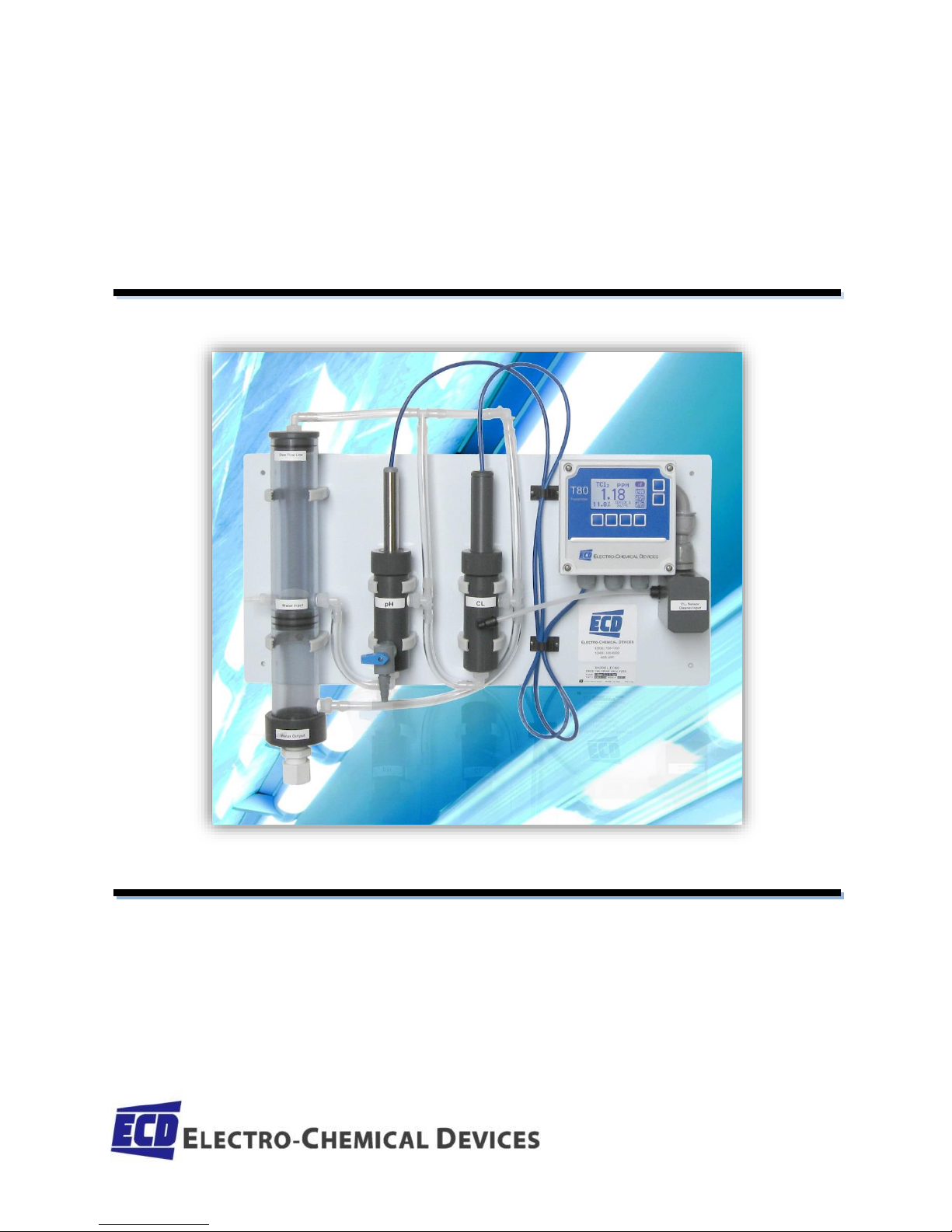
MODEL TC80 TOTAL CHLORINE ANALYZER
MODEL DC80 DECHLORINATION ANALYZER
TC80 IM Rev. C
Page 2

Page 1 Model TC80
Page 3
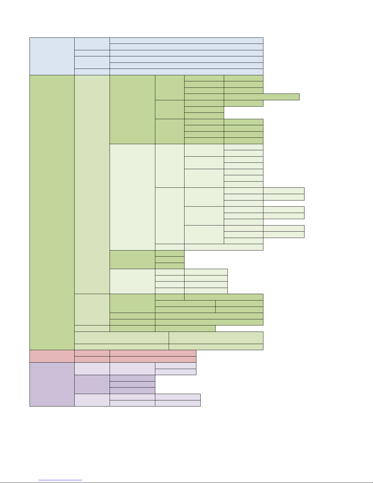
SCREEN MAP
CAL
(Calibration)
Auto
Cal 1 (Offset) using Calibration Solution
Cal 2 (Slope) using Calibration Solution
Standardize
Enter Grab Sample Determined Value
Manual
Enter Offset, the PV value and associated mV
Enter Slope, mV/pH, mV/decade, mV/ppm…
Temp
Enter measured Temperature
CONFIG
(Configuration)
XMTR
LCD
Set Up
Temp. Format
°C or °F
Contrast
Adj. 0-100%
Back Light
Enter ON time
Range Lock
Choose: Auto, ppb, ppm, ppT
Graph
Line
Screen Duration
Gauge
Bar
Label
TAG ID
Enter Name
TAG
ON/OFF
POP UP
ON/OFF
SENSOR
Enter Name
Output
4-20 mA
(1 or 2)
Range (PV or
Temp.)
4 mA =
20 mA =
More → CAL
Trim 4.00 mA
Trim 20.00 mA
More → Fault
3.5 mA
22 mA
NONE
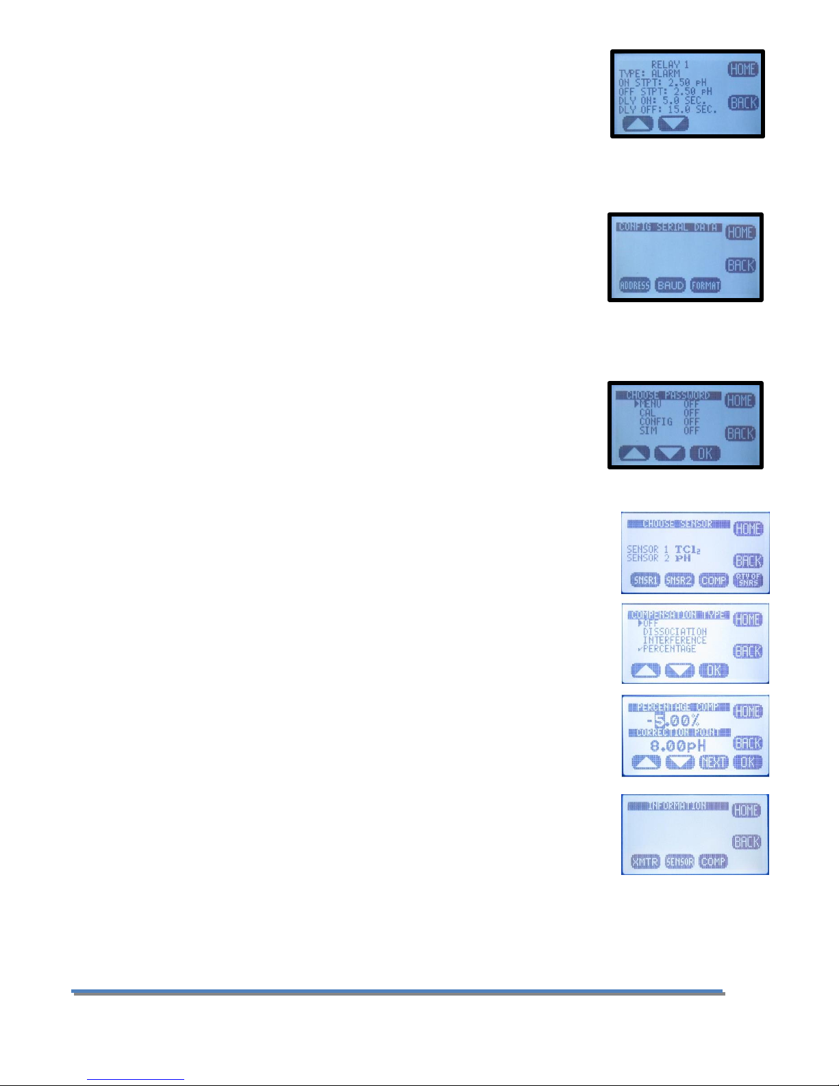
RELAY
Relay 1
Alarm
Set Point
Timed
Period, Duration
Fault
Relay 2
Alarm
Set Point
Timed
Period, Duration
Fault
Relay 3
Alarm
Set Point
Timed
Period, Duration
Fault
HOLD
Time out: None, 15 min, 30 min…
Serial
Address
Baud rate
Format
Password
Menu
Off/On “ _ _ _ _ “
CAL
Off/On “ _ _ _ _ “
CNFG
Off/On “ _ _ _ _ “
SIM
Off/On “ _ _ _ _ “
Sensor
Sensor 1 or 2
Type
Choose Type: pH, Cond, ORP…..
T COMP
Enter % Comp
ISO PT
Enter mV value
Qty of Sensors
Choose 1 sensor or 2 sensors
COMP
Dissociation, Interference, Percentage, OFF
Load Default
Sensor/Transmitter
Yes/No
DAMP or MORE
Enter Signal Dampening (# of readings to
average, 0-100)
OFFSET (DC80 only)
Enter Offset value
INFO
(Information)
XMTR
Configuration, Serial #, Name, Outputs
Sensor
Calibration logs, Serial #, Name
SIM
(Simulate)
System
Sensor 1 or 2
Fixed value
Ramp
Relays
#1 ON/OFF
#2 ON/OFF
#3 ON/OFF
4-20 mA
4-20 mA Ch 1
Enter Value
4-20 mA Ch 2
Enter Value
2
Page 4

PREFACE
Purchasing products from Electro-Chemical Devices, Inc. provides you with the finest liquid analytical
instrumentation available. If this is your first purchase from ECD, please read the entire manual before installing
and commissioning your new equipment.
Manuals are accessible on the ECD website at http://www.ecdi.com/literature/manuals.html .
If there are any questions concerning this equipment, please contact your local ECD representative, or the
factory directly at:
Electro-Chemical Devices, Inc.
1681 Kettering
Irvine, CA 92614 USA
Telephone: +1-949-336-6060
FAX: +1-949-336-6064
Website: www.ecdi.com
Email: sales@ecdi.com
Page 3 Model TC80
Page 5
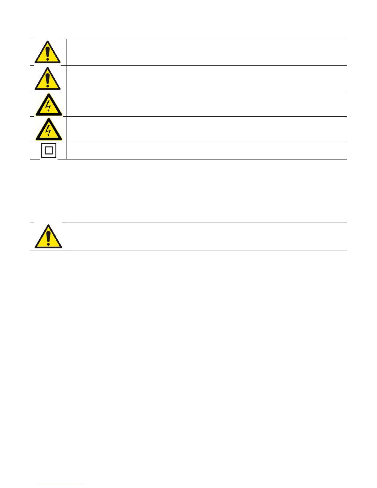
SYMBOLS USED IN MANUAL
This symbol is used to designate important information, warnings and cautions. Failure to follow
this information could lead to harm to the instrument or user.
No operator serviceable parts, service by authorized service personnel only.
This symbol is used to designate a WARNING “Risk of Electrical Shock”
Disconnect supply before servicing
Equipment protected throughout by double insulation.
Read the complete manual before installing or using the equipment.
Contents of this manual are believed to be correct at the time of printing and are subject to change without
notice. ECD is not responsible for damage to the instrument, poor performance of the instrument or losses
resulting from such, if the problems are caused by:
• Incorrect operation by the user.
• Use of the instrument in incorrect applications.
• Use of the instrument in an inappropriate environment or incorrect utility program (power supply).
• Repair or modification of the related instrument by anyone not authorized by ECD.
• There are no operator accessible parts. Service and maintenance to be done by authorized personnel only.
• If the equipment is used in a manner not specified by the manufacturer, the protection provided by the
equipment may be impaired.
© 2014 Electro-Chemical Devices, Inc. All rights reserved. No part of this manual may be used or reproduced in
any form or by any means, or stored in a database or retrieval system without prior written permission from
Electro-Chemical Devices, Inc. Making copies of any part of this manual for any purpose other than personal use
is a violation of United States copyright laws. Document printed in the United States of America.
4
Page 6

Table of Contents
Screen Map .................................................................................................................................................................2
TERMS AND CONDITIONS OF SALE .............................................................................................................................9
RETURN GOODS POLICY .......................................................................................................................................... 10
UNPACKING THE INSTRUMENT ............................................................................................................................... 11
INSTRUCTION MANUAL REVISION ........................................................................................................................... 11
1.0 GENERAL DESCRIPTION ..................................................................................................................................... 12
1.1 FEATURES ...................................................................................................................................................... 13
1.2 SPECIFICATIONS ............................................................................................................................................. 13
1.2.1 Sensors and Flow Train ........................................................................................................................... 13
1.2.2 TC80 Analyzer ......................................................................................................................................... 13
1.3 Model Codes .................................................................................................................................................. 14
2.0 INSTALLATION.................................................................................................................................................... 15
2.1 MOUNTING .................................................................................................................................................... 15
2.2 WIRING .......................................................................................................................................................... 16
2.2.1 Wiring, power ......................................................................................................................................... 16
2.2.2 Wiring, Sensor ........................................................................................................................................ 17
2.2.3 Wiring, 4-20 mA Outputs ........................................................................................................................ 17
2.2.4 Wiring, Contact Relay Outputs ............................................................................................................... 17
2.2.5 Wiring, Serial Output MODBUS RTU ...................................................................................................... 17
2.3 INSTALLING the SENSORS .............................................................................................................................. 18
2.4 PLUMBING ..................................................................................................................................................... 18
2.4.1 Sample Requirements ............................................................................................................................ 18
2.4.2 Connecting the Inlet and Drain fittings .................................................................................................. 18
2.4.3 Adjusting the Sample Flow Rate ............................................................................................................. 18
2.5 Connecting the Optional Spray Cleaner ........................................................................................................ 19
2.6 Connecting the Optional Chlorine Dosing Pump (DPC80) ............................................................................. 19
3.0 OPERATION ........................................................................................................................................................ 20
3.01 Influences on the Measurement ............................................................................................................. 20
pH Value .......................................................................................................................................................... 20
3.02 Influences on the Measurement ............................................................................................................. 20
Flow ................................................................................................................................................................. 20
Page 5 Model TC80
Page 7

3.03 Influences on the Measurement ............................................................................................................. 21
Temperature .................................................................................................................................................... 21
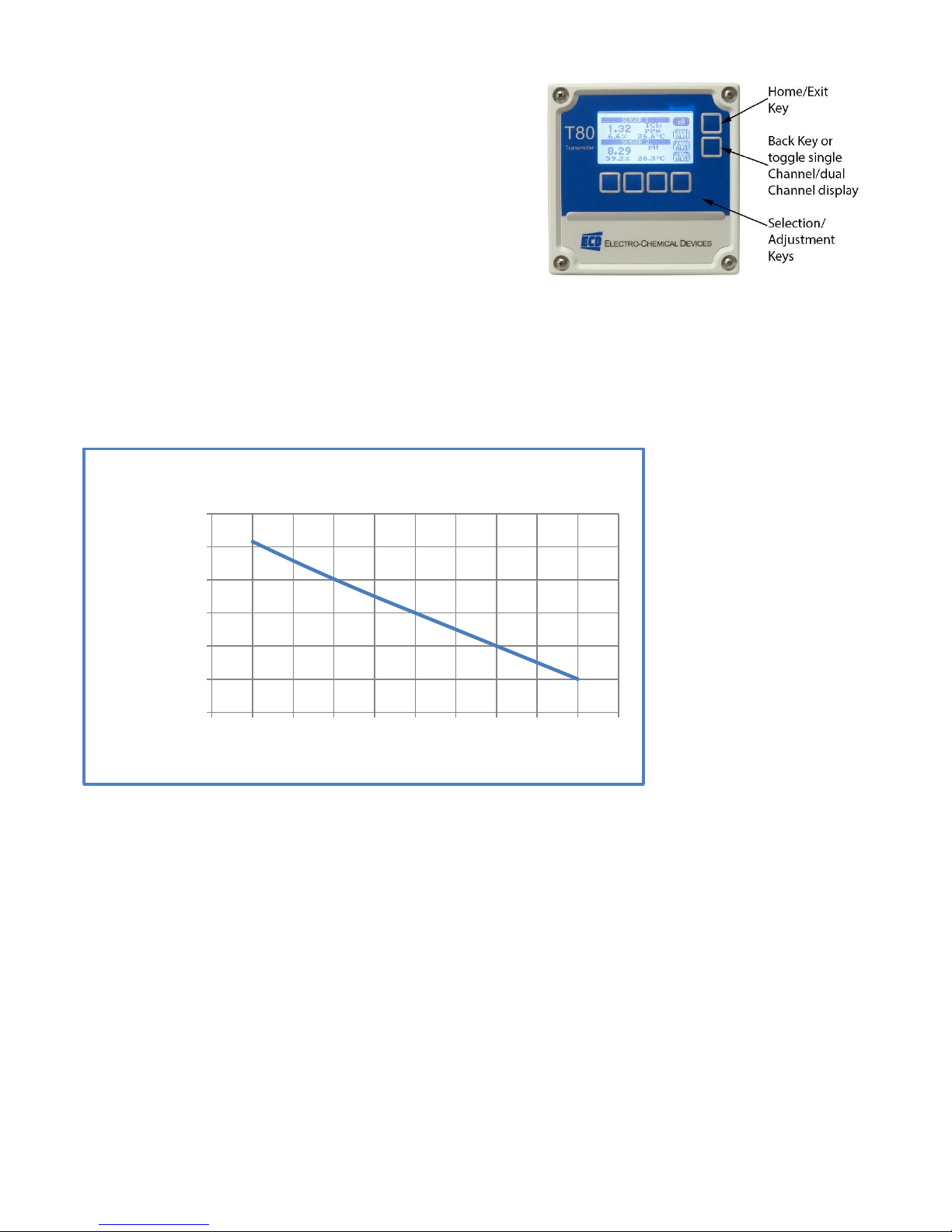
3.1 KEYS ............................................................................................................................................................... 22
3.1.1 Home/Exit Key ........................................................................................................................................ 22
3.1.2 Back/Hold Key ......................................................................................................................................... 22
3.1.3 Selection Adjustment Keys ..................................................................................................................... 22
3.1.4 Alpha Numeric Entry............................................................................................................................... 23
3.2 MENU STRUCTURE ........................................................................................................................................ 23
3.2.1 HOLD (Output Hold) ............................................................................................................................... 23
3.2.2 CAL (Calibration Menu) .......................................................................................................................... 23
3.2.3 CONFIG (Configuration Menu) ............................................................................................................... 24
3.2.4 INFO (Information Menu) ....................................................................................................................... 25
3.2.5 SIM (Simulation Menu) ........................................................................................................................... 25
3.2.6 Fault Screens........................................................................................................................................... 26
3.3 OUTPUT CONFIGURATION GUIDE ................................................................................................................. 26
3.3.1 Configure 4-20 mA output range ............................................................................................................ 27
3.3.2 Configure 4-20 mA Fault Condition and Cal ........................................................................................... 27
3.3.3 Configure Alarm Relays (Relays Optional) .............................................................................................. 27
3.3.4 Exit Menus and Return to Main Display ................................................................................................. 28
3.3.5 Sensor Start Up ....................................................................................................................................... 28
3.4 USER SELECTABLE OPTIONS .......................................................................................................................... 28
3.4.1 Screen Lighting ....................................................................................................................................... 28
3.4.3 Graphical display .................................................................................................................................... 29
3.4.4 TAG Transmitter Name ........................................................................................................................... 29
3.4.5 Sensor Name........................................................................................................................................... 29
3.4.6 Password Protection ............................................................................................................................... 30
4.0 CALIBRATION ..................................................................................................................................................... 31
4.0.1 AUTO Calibration description ................................................................................................................. 31
4.0.2 STANDardize Calibration description ..................................................................................................... 31
4.0.3 MANUAL Calibration description............................................................................................................ 31
4.1 pH Calibration Procedures ............................................................................................................................. 33
4.1.1 AUTO Cal using pH 4.01, 7.00, 10.00 buffers ......................................................................................... 33
4.1.2 AUTO Cal using other pH buffers............................................................................................................ 33
6
Page 8

4.1.3 Standardize ............................................................................................................................................. 33
4.2 Total Chlorine Calibration Procedures .......................................................................................................... 34
4.2.1 Auto Cal .................................................................................................................................................. 34
4.2.2 Standardize ............................................................................................................................................. 35
4.2.3 Manual Cal .............................................................................................................................................. 35
5.0 MAINTENANCE .................................................................................................................................................. 36
5.1 Total Chlorine Sensor .................................................................................................................................... 36
5.1.1 Removing or Replacing the Membrane ................................................................................................. 36
5.1.2 Polishing the Cathode ............................................................................................................................. 36
5.1.3 Refilling the Sensor ................................................................................................................................. 36
5.2 pH Sensor ....................................................................................................................................................... 37
5.2.1 Electrode Cartridge Installation .............................................................................................................. 37
5.2.2Electrode Cartridge Replacement ........................................................................................................... 37
5.2.3 Electrode Cleaning .................................................................................................................................. 37
5.2.4 pH Electrode Cartridge Cleaning ............................................................................................................ 38
5.3 Constant Head Flow Controller (CHFC) ......................................................................................................... 38
6.0 TROUBLESHOOTING .......................................................................................................................................... 39
7.0 PARTS AND ACCESSORIES .................................................................................................................................. 41
7.1 TC80 Replacement parts ............................................................................................................................... 41
7.2 T80 Front Panel Control Board Exploded ...................................................................................................... 42
7.3 T80 Front Panel Control Board Exploded, with Relays .................................................................................. 42
7.4 T80 Transmitter Case, back with Cable Glands ............................................................................................. 42
7.5 T80 Replacement Parts .................................................................................................................................. 43
APPENDIX ................................................................................................................................................................ 44
A. Auto Cal Buffer Tables ..................................................................................................................................... 44
B.MODBUS RTU Register Listing .......................................................................................................................... 44
03 (0x03) Read Holding Registers .................................................................................................................... 44
06 (0x06) Write Single Register ....................................................................................................................... 45
Registers .......................................................................................................................................................... 45
Fault Status ...................................................................................................................................................... 49
Warning Status ................................................................................................................................................ 49
Sensor Type ..................................................................................................................................................... 49
C. Auto Spray Cleaner .......................................................................................................................................... 50
Page 7 Model TC80
Page 9

ADENDUM: DC80 De-Chlorination Analyzer ........................................................................................................... 51
DC80 Start Up Procedures ................................................................................................................................... 52
8
Page 10

TERMS AND CONDITIONS OF SALE
1. ACCEPTANCE. If this writing differs in any way from the terms and conditions of Buyer's order or if this writing is construed as an acceptance or as a confirmation acting as an
acceptance, then Seller’s acceptance is EXPRESSLY MADE CONDITIONAL ON BUYER’S ASSENT TO ANY TERMS AND CONDITIONS CONTAINED HEREIN THAT ARE DIFFERENT
FROM OR ADDITIONAL TO THOSE CONTAINED IN BUYER'S WRITING. Further, this writing shall be deemed notice of objection to such terms and conditions of Buyer. If this
writing is construed as the offer, acceptance hereof is EXPRESSLY LIMITED TO THE TERMS AND CONDITIONS CONTAINED HEREIN. In any event, Buyer's acceptance of the
goods shall manifest Buyer's assent to Seller's terms and conditions. No addition to or modification of these terms will be effective, unless set forth in writing and agreed to by
Seller.
2. WARRANTIES AND REMEDIES
a. Warranty. Seller warrants to Buyer that it holds and will pass marketable title to the goods sold hereunder. Seller warrants to Buyer that the items and components
manufactured by Seller will be free from defects in material and workmanship (subject, however, to tolerances and variances permitted by the trade hereunder) for a
period one (1) year for non-consumable products. Consumable electrodes and sensors have a conditional warranty based shelf life and process conditions and is
determined by Seller.
b. Exclusion and Conditions. Seller’s obligations with respect to the express warranties and remedies contained herein are conditioned on the following: (i) Buyer's return
of the non-conforming goods, if authorized by Seller: (ii) Buyer shall not assign its rights under these express warranties and any attempted assignment shall render
such warranties, but not any disclaimers or limitations, void and the goods sold shall be sold AS IS; and (iii) all products shall be carefully inspected for damage by Buyer
upon receipt, be properly calibrated for Buyer's particular use, and be used, repaired, and maintained by Buyer in accordance with the instructions set forth in Seller’s
product literature. Repair and maintenance by non-qualified personnel, product subjected to misuse or negligence, and/or damaged during shipment will invalidate the
warranty, as will the use of non-approved consumables or spare parts. As with any other sophisticated product, it is essential, and a condition of Seller’s warranty, that
all personnel using the product be fully acquainted with its use, capabilities and limitations as set forth in the applicable product literature.
3. DISCLAIMER OF IMPLIED WARRANTIES. Seller gives no warranties except those expressly contained herein. Seller disclaims all other warranties implied by law usage of the
trade, course of dealing or course of performance including, but not limited to, the implied warranties of MERCHANTABILITY and fitness for a particular purpose.
4. LIMITATIONS OF LIABILITY. The following limitations of Seller's liability are acknowledged by the parties to be fair and reasonable and shall apply to any act or omission
hereunder, and to any breach of this contract of which these terms and conditions form a part:
a. Disclaimer of Damage. In no event shall Seller be liable for special, indirect, consequential or incidental damages whether arising under contract, warranty,
tort, strict liability or any other theory of liability. Such damages include but are not limited to loss of profits, loss of use of goods, damage to property, and
claims of third parties.
b. Suitability. Buyer acknowledges that it alone has determined the intended purpose and suitability of the goods sold hereunder. It is expressly agreed by the
parties that any technical or other advice given by the Seller with respect to the use of the goods or services is given without charge and at B uyer's risk;
therefore Seller assumes no obligation or liability for the advice given or results obtained.
c. Notice and Time of Claims.
i. Buyer agrees to check and inspect all products against shipping papers and for damage or shortage upon receipt of goods at destination.
ii. Every claim for shortage, damage in transit, or other cause visible upon inspection shall be deemed waived by the Buyer, or the Buyer’s customer in
iii. The parties expressly waive the statute of limitations and agree that any legal proceeding for any breach of this contract shall be waived unless filed
5. FORCE MAJEURE. Seller shall not be liable for any delay in delivery, or failure to deliver, due to any cause beyond the Seller’s control including but not limited to fires, floods, or
other forces of the elements; strikes, or other labor disputes; accidents to machinery; acts of sabotage; riots; precedence or priorities granted at the request or for the benefit,
directly or indirectly of the federal or any state government or any subdivision or agency thereof; delay in transportation or lack of transportation facilities; restrictions imposed
by federal, state or other governmental legislation or rules or regulations thereof. If Seller, in its sole discretion, determines that Seller’s performance hereunder would result in
a loss to Seller’s on this sale as computed under Seller’s normal accounting procedures because of causes beyond Seller's control, then the Seller may terminate this agreement
in whole or in part without liability for any delay in the delivery of, or failure to deliver, the goods sold hereunder
6. TAXES AND OTHER CHARGES. The Buyer will pay, or reimburse Seller if it pays, any and all taxes or tariffs or any other similar charges imposed upon this contract, the goods
covered hereby or the delivery or use or resale thereof.
7. FREIGHT CHARGES. If the sale hereunder is other than F.O.B. Seller's facility, this acknowledgement is based upon the freight charges now in effect. In the event of an increase
or decrease in applicable freight charges before the goods are shipped, such charge in freight will be for the Buyer's account.
8. PRICES AND DELIVERY. Prices quoted herein are F.O.B. shipping point. Deliveries specified are only our best estimate and are subject to change. This quotation is based upon
freight charges now in effect. Buyer will be invoiced at the freight charge prevailing at the date of shipment. Prices are firm for orders meeting Seller's normal shipping
schedules. If shipments are held or postponed for any reason other than Seller's fault, and a price increase becomes effective during the period of such hold or postponement,
the increase will apply to all shipments that are held or postponed thirty (30) days or more from the effective date of the increase.
9. PAYMENTS. If in the judgment of Seller the financial condition of Buyer at any time prior to shipment does not justify the terms of payment specified, Seller may cancel the
order, withhold shipment, and/or require full or partial payment in advance. If payment is not made when due, Seller may suspend all future delivery or other performance with
respect to Buyer without liability or penalty and, in addition to all other sums payable hereunder, Buyer shall pay to Seller (i) the reasonable costs and expenses incurred by
Seller in connection with all actions taken to enforce collection or to preserve and protect Seller’s rights hereunder, whether by legal proceedings or otherwise, including
without limitation reasonable attorneys’ fees, court costs and other expenses and (ii) interest on all amounts unpaid after 30 days charged at the monthly rate of 1-1/2% or the
highest rate permitted by law, whichever is lower.
10. CANCELLATION OR ALTERATION. Buyer may not alter or cancel any order without Seller’s written consent. For any order altered or cancelled with Seller's consent, Buyer must
pay for all expenses and labor incurred up to the time of Seller’s consent, plus a reasonable percentage for profit. Any order delayed or deferred by Buyer will be subject to price
escalation for increased costs of production, and any other expenses caused by the delay. Material on such orders will be stored at Buyer's risk. Seller reserves the right to
invoice Buyer and require payment before shipment of any delayed or deferred order.
11. TITLE AND RISK OF LOSS. Title and risk of loss shall pass to buyer at Irvine, California, unless otherwise specified in the contract. If delivery is made by common carrier, risk of
loss shall pass upon delivery to the carrier. Claims for loss or damage in transit must be made by Buyer to the carrier. Seller accepts no responsibility for loss or damage to
product in transit.
12. PATENT OR TRADEMARK INFRINGEMENT. If the goods sold hereunder are to be prepared for manufacture according to Buyers specification, Buyer shall indemnify Seller
against any claim or liability for patent, trademark, service mark or trade name infringement on account of preparation, manufacture and/or sale.
13. NON-WAIVER. If Government Contract Regulations require the addition, deletion, or modification of these terms and conditions upon prior n otification to Seller and Seller's
written acceptance thereof, such changes shall become a part of these terms and conditions. Seller shall not be bound by any Government Contract Regulations applicable to
Buyer’s contracts with the U.S. Government unless Buyer has expressly acknowledged, on the face of this document, the applicability of such Regulations to the transaction
between Buyer and Seller contemplated herein. Absent such acknowledgement, Seller is making the assumption in issuing this document that no such Regulations apply.
the case of resale, unless delivered in writing to Seller by Buyer thirty (30) days from the tender of delivery of the goods to Buyer, provided, however,
that claims for shortage must be made within seven (7) days of receipt.
within one (1) year after the accrual of the cause of action thereof.
Page 9 Model TC80
Page 11

14. JURISDICTION. All such disputes shall be resolved in a court of competent jurisdiction in Orange County, California. Buyer hereby consents to the jurisdiction of the State and
Federal Courts sitting in Orange County. Notwithstanding the above, should either party contest the jurisdiction of such courts, the other party may institute its suit in any court
of competent jurisdiction.
15. APPLICABLE LAW. All questions arising hereunder or in connection with the quotations or any order submitted in connection therewith and/or the performance of the parties
hereunder shall be interpreted and resolved in accordance with the laws of the state of California without regard to its conflict of law provisions and excluding the United
Nations Convention on the International Sale of Goods.
RETURN GOODS POLICY
All requests for returned goods must be initiated through our Customer Service Department. Please call our
phone number (949) 336-6060 with the specifics of your request. The following conditions must be satisfied for
consideration of applicable credit for the return of products purchased from Electro-Chemical Devices:
1) The item is unused and in the original package.
2) The item was shipped directly from Electro-Chemical Devices.
3) The item has not been damaged in shipment to Electro-Chemical Devices.
4) Items containing date-sensitive parts such as electrodes, must be returned within 1 month of the
invoiced date.
5) Items without date-sensitive parts must be returned within 3 months of the invoiced date.
A Return Merchandize Authorization Number must be obtained from Customer Service and be provided on all
paperwork and packaging. To obtain a Return Merchandize Authorization Number, please provide the reason
for return, the date of purchase, your original purchase order number, and either our order number or our
invoice number. The issuance of a Return Merchandize Authorization Number is a verbal approval for return
only and does not guarantee credit or allowance. Returned goods must be received within 30 days of the
issuance date of the Return Merchandize Authorization Number or it will become null and void.
Necessary physical and mechanical inspection is completed upon receipt of the item. Applicable credit or
equivalent allowance is determined after inspection of the returned item. If all of the above conditions are met,
and the item has been approved to return to our stock, a restocking charge of 25% of the purchase price is
deducted from the applicable credit.
10
Page 12
UNPACKING THE INSTRUMENT
WARNING Electrical installation must be in accordance with the National Electrical Code
(ANSI/NFPA-70), Canadian Electrical Code and/or any other applicable national or local
codes.
Your Electro-Chemical Devices instrument has been carefully packaged to protect it from damage during
shipment and dry storage. Upon receipt please follow the procedure outlined below.
1. Before unpacking, inspect the condition of the shipping container to verify proper handling by the
carrier. If damage is noted, save the shipping container as proof of mishandling for the carrier.
2. Check the contents of the shipping container with the items and quantities shown on the packing list.
Immediately report any discrepancies to ECD.
3. Save the original packing material until you are satisfied with the contents. In the event the product(s)
must be returned to ECD, the packing material will allow you to properly ship it to ECD.
4. Familiarize yourself with the instrument before installation, and follow proper installation and wiring
procedures.
5.
Installation and wiring
Failure to follow the proper instructions may cause damage to this instrument and warranty invalidation.
Use only qualified personnel to install, operate and maintain the product.
The Model T80 transmitter should only be used with equipment that meets the relevant IEC, American or
Canadian standards. ECD accepts no responsibility for the misuse of this unit.
Basic Parts List
1. Model TC80 Transmitter and sensors, Panel Mounted
2. Total Chlorine refill Solution
3. Instruction Manual
INSTRUCTION MANUAL REVISION
Revision Date Remarks
A 09/14 Initial release
B 12/14 Wiring updated
Page 11 Model TC80
Page 13
1.0 GENERAL DESCRIPTION
The TC80 is designed for use in drinking water, industrial cooling and
rinse water or other samples of fresh water that use chlorine in the
range of 0-20 ppm as a disinfectant. Chlorine is commonly added to
water as chlorine gas or sodium hypochlorite (bleach). Chlorine exists
in water as a pH dependent mixture of hypochlorous acid and
hypochlorite ion. The sum of these two components is referred to as
Free Chlorine. Organic compounds containing chlorine may be added
to the water or form in the water by reaction with the Free Chlorine.
Chlorine may also react with ammonia in the water to form
chloramines. Together these compounds are referred to as Bound or
Combined Chlorine.
Total Chlorine is the sum of the Bound Chlorine and Free Chlorine in the sample, the TC80 measures Total
Chlorine.
The TC80 is a complete system for measuring Total Chlorine. The panel mounted system includes a Constant
Head Flow Controller (CHFC), Total Chlorine sensor (TCS) and Flow Cell, pH sensor (S80pH) and Flow Cell and the
T80 Transmitter. Simply supply power to the T80 Transmitter and plumb the sample line in and the drain line
out and the TC80 is ready to use.
The CHFC maintains a constant sample flow to the pH and Chlorine flow cells. Pressure regulators and
rotameters are not needed to maintain a constant flow rate, the CHFC provides trouble free sample conditioning
between 10 and 80 gal/hr.
The Total Chlorine Sensor (TCS) is a three electrode amperometric sensor with a micro porous PTFE membrane,
a gold cathode, a silver/silver halide anode and a 304 SS counter electrode. The counter electrode design
provides a stable reference, virtually eliminating drift and the associated maintenance.
The T80 Transmitter applies a fixed voltage on the anode and cathode and measures the current flow.
Chlorine compounds diffuse through the PTFE membrane and react with a potassium iodide fill solution. The
iodide is oxidized to iodine by the various chlorine compounds. The iodine is then reduced (gains electrons) by
the gold cathode back to iodide ion. Silver on the anode is oxidized (donates electrons) to silver iodide
completing the current loop. With stable temperature, pH and sample flow, the current flow is proportional to
the total chlorine concentration.
Many competitive total chlorine analyzers require service on a monthly or bimonthly basis. The TCS is an
amperometric sensor that requires refilling every 3-6 months. The chloride concentration of the electrolyte
increases over time as the measured chlorine is reduced to chloride by the potassium iodide degrading the
electrolyte. The replaceable PTFE membrane is designed for long term stability and typically lasts over a year.
Replacing the PTFE membrane and recharging the electrolyte is easily accomplished without the use of tools.
The Model T80 transmitter can be 24 VDC powered or 100-240 VAC line powered. The standard configuration
has a 4-20 mA output and a RS485 serial communication port with MODBUS®RTU output. Alarm relays are
standard on either line powered transmitter.
12
Page 14

1.1 FEATURES
Panel Mounted System, Easy Installation
Plumb and Play Design, Ready to Use
Automatic pH Compensation, No Expensive Reagents to
mix or spill
Automatic Flow Control, Eliminates Pressure Regulators
and Rotameters
T80 Transmitter Capability, Dual Measurements,24VDC or
110/220 VAC Power, Graphical Plots
Compliant with EPA Method 334.0
1.2 SPECIFICATIONS
1.2.1 SENSORS AND FLOW TRAIN
Chlorine Sensor:
Digital protocol, Potentiostatic, Gold cathode/Silver-Silver Halide anode, 316L SS counter electrode
pH Sensor:
Digital S80 protocol, 316L stainless steel body with replaceable electrode cartridge
Measurement Range:
Chlorine: 0.05 to 20 ppm (High Range)
0.005 to 2.00 ppm (Low Range)
pH: 4 to 14 pH
Operating Temperature:
0° C to 50° C (32° F to 122° F)
Min/Max Flow:
38 L/hr. to 300 L/hr. (10 gal/hr. to 80 gal/hr.)
Wetted Materials:
PVC, PP, PVDF, PTFE, Glass, 316 SS
Process Connections:
Input ¼” FNPT with barb fitting, Drain ¾” FNPT
Response Time:
T90 in 2 minutes
Electrolyte Life:
3 to 6 months
1.2.2 TC80 ANALYZER
Measurements:
Chlorine: 0.00 ppb to 22.00 ppm
pH: 0.00 to 14.00 pH
pH Compensation of Total Chlorine:
pH 4 - 12
Display:
128 x 64 pixels (2.75” x 1.5”) LCD, Black on Grey background, Blue on White background with LED backlight on
Outputs:
(1) 4-20 mA for Total Chlorine set to Sensors Range
Page 13 Model TC80
Page 15

(1) 4-20 mA for pH (Optional) set 0-14 pH
Model TC80-
Sensor type
and Range
0 0.05 to 20 ppm Total Chlorine (Standard)
1 0.005 to 2.00 ppm Total Chlorine
2 0.05 to 20 ppm Total Chlorine (Seawater)
3 0.005 to 2.00 ppm Total Chlorine (Seawater)
pH Comp
1 pH Sensor (Standard)
Power
-1 24 VDC Powered Transmitter
-2 100-240 VAC powered Transmitter
Outputs and
Relays
1 (x1) 4-20mA Outputs & (3) Relays
2 (x2) 4-20mA Outputs & (3) Relays (Standard)
Spray cleaner
00 No Spray Cleaner
10 Spray Cleaner on Chlorine
TC80- 0 1
-2
1
10
Modbus RTU (standard)
Alarm Relay Ratings:
Three (3) SPDT, 1 form C, 250 VAC, 10 Amp resistive maximum, relays, user configurable as Hi/Lo alarms with
expiration timer, Periodic Timers or Fault alarms
Input Power
Code -1 24 VDC (18-36 VDC @ 250 mW minimum)
Code -2 100-240 VAC, 50/60 Hz, 4W, protected with 250V, 1A, Slow Blow fuse
Enclosure:
Beige Polycarbonate, IP65, weatherproof, ½ DIN, (L x W x D) 5.7” X 5.7” X 3.5” (14.4cm X 14.4cm X 9.0cm)
Environmental Conditions:
Outdoor use (IP65)
Ambient Temperature -20°C - 70°C (24 VDC Models)
-20°C - 60°C (100-240 VAC Models)
Storage Temperature -30°C - 85°C
Relative Humidity 0 – 80%, up to 31°C
Decreasing linearly to 50% RH a 40°C
Altitude Up to 2000 m (6500 ft)
Mains Supply Voltage Fluctuations up to ±10% of the nominal voltage
Transient over voltages: CAT II
Pollution Degree: 2
1.3 MODEL CODES
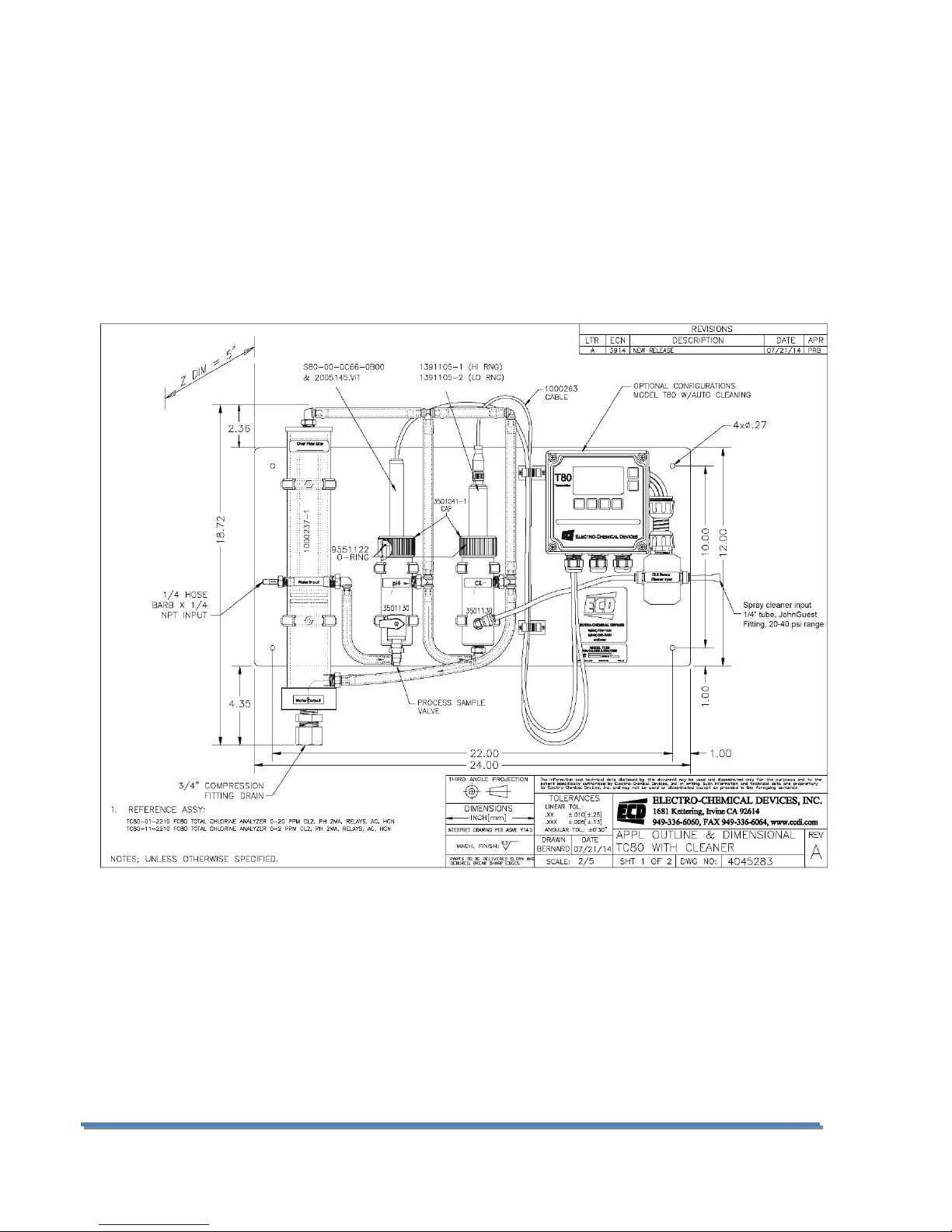
Example above shows part# TC80-01-2110, a two channel TC80 transmitter, 0.05 to 20 ppm Total Chlorine range
and S80 pH sensor, 110/220 VAC powered with one 4-20 mA output with MODBUS RTU, 3 Relays (one used for
Spray Cleaning option) and spray cleaner.
14
Page 16
2.0 INSTALLATION
Mount the TC80 in a location where there is easy access to the analyzer and sensors. Install the system in an
area where vibrations, electromagnetic and radio frequency interference are minimized or absent.
Do not mount in direct sunlight or areas of extreme heat. The TC80 is suitable for outdoor use if mounted with a
protective cover or sunshield.
2.1 MOUNTING
The TC80 panel is drilled with 4 x 0.265” holes, one at each corner, and is designed to use ¼” -20 hardware or
6mm metric hardware.
Page 15 Model TC80
Page 17
2.2 WIRING
Warning: RISK OF ELECTRICAL SHOCK
Disconnect Power before opening instrument.
WARNING Electrical installation must be in accordance with the National Electrical Code
(ANSI/NFPA-70), Canadian Electrical Code and/or any other applicable national or local
codes.
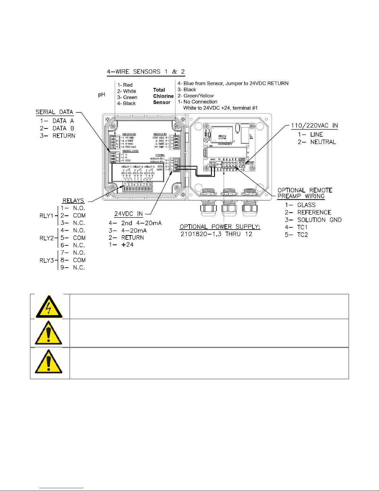
Electrical wiring should only be conducted by qualified personnel. See the T80 wiring diagram in Figure 2.2.2
Figure 2.2.2 4-Wire Transmitter, 24VDC or /110/22 VAC, MODBUS, Relays/Optional Digital Preamp
2.2.1 WIRING, POWER
ECD recommends using a thermoplastic, outdoor sunlight resistant jacketed cable, wet location rated and ½”
flexible conduit. The power should be hard wired with a switch or breaker to disconnect the analyzer from the
16
Page 18

main power supply. Install the switch or breaker near the analyzer and label it as the Power Switch for the
analyzer.
24VDC (4 wire configuration)
Attach the 24VDC power cable to terminals #1 and #2 as shown in Figure 2.2.2 and on the diagram inside of the
T80 cover. Attach the 4-20 mA1 cable to terminals #3 (out) and #2 (return)single channel unit and attach the 420 mA2 cable to terminals #4 (out) and #2 (return) for a two channel instrument. Feed the cables through the
gland fitting on the right hand side of the T80. Tighten the cable gland to provide a good seal to the cable. The
instrument can be powered up at this point with no harm to the analyzer but it is best to wait until the sensors
are installed.
110/220 VAC (4 wire configuration)
Attach power cable as shown in Figure 2.2.2 or as on the diagram inside of the T80 cover. Feed the cable
through the gland fitting on the right hand side of the T80. Tighten the cable gland to provide a good seal to the
cable. The instrument can be powered up at this point with no harm to the analyzer but it is best to wait until
the sensors are installed.
2.2.2 WIRING, SENSOR
The Total Chlorine Sensor and the S80 pH Sensor were connected to the TC80 analyzer at the factory, no
additional connections are necessary. Color coded connections for these sensors are shown in the wiring
diagrams in Section 8.3 or on the inside cover of the T80 transmitter.
When replacing a sensor, attach the sensor wires as described above. Feed the sensor cable through the gland
fitting on the left hand side of the T80. Do not use the same gland fitting for the AC power or Alarm/Relays. The
green terminal strip connectors are detachable from the circuit boards. Remove the connector by pulling
straight back from the circuit board.
2.2.3 WIRING, 4-20 MA OUTPUTS
24 VDC or 110/220 VAC powered instruments:
For instruments powered with 24VDC or with the internal 110/220 VAC power supply, Model T80-XX-1X-XX
(24VDC) and T80-XX-2X-XX (110/220 VAC), connect the 4-20 mA cable(s) to terminals #3 (out) for channel 1 and
#2 (return) and to terminals #4 (out) for channel 2 and #2 (return).
2.2.4 WIRING, CONTACT RELAY OUTPUTS
The standard configuration has three SPDT 230V 5 A relays that can be wired either normally open (NO) or
normally closed (NC). The default configuration is set to use the relays as normally open. If the optional spray
cleaner was ordered then one of the relays is used to control the cleaning cycle.
2.2.5 WIRING, SERIAL OUTPUT MODBUS RTU
Attach the sensor wires as shown in Figure 2.2.2 or as described on the diagram inside the T80 cover. Feed the
sensor cable through the gland fitting on the left hand side of the T80. Do not use the same gland fitting for the
AC power or Alarm/Relays. See MODBUS command register in Appendix B.
Page 17 Model TC80
Page 19

2.3 INSTALLING THE SENSORS
The TC80 is supplied with the sensor cables pre-wired to the analyzer. The TC80 instrument and sensors were
calibrated at the factory and should be ready for use when assembled. However, changes may have occurred
during shipping and storage requiring recalibration. (See Calibration section 4.2 below)
The pH sensor mounts in the Flow Cell using an o-ring sealed flange/union mount with threaded locking cap.
First remove the protective cap from the sensing end of the sensor and save it for future use, the cap contains a
potassium chloride solution use care when removing the cap from the sensor. Insert the sensor into the flow
cell. There is an o-ring seal inside the flange that seals against the face of the flow cell. Slide the sensor into the
flow cell and then hand tighten the knurled compression cap to fix its position.
The Chlorine sensor is held in the flow cell with a union nut. Slide the sensor into the flow cell and hand tighten
the compression cap after filling the sensor with electrolyte.
1. Lift the silicone band to Expose the vent hole and unscrew the measuring cap from the sensor.
2. Fill the cap to the bottom of the threads with the gelled electrolyte and tap it gently to dislodge any
trapped bubbles inside the cap.
3. Screw the sensor into the measurement cap at a 45° angle ensuring all air inside the chamber is purged
through the vent hole on the side of the cap.
4. When the o-ring begins to seal continue slowly tightening until it hits the stop.
5. Replace the silicone band back over the vent hole and rinse the purged electrolyte from the sensor body
with water.
The sensor is ready to use, re-polarize the sensor for 60 minutes before calibration.
Refill the sensor with electrolyte (PN 100246-1) every 3-6 months, depending on the chlorine level measured.
The measured chlorine is reduced to chloride inside the cell and must be periodically removed. Samples with
around 5 ppm total chlorine require the sensor to be refilled every 3-4 months.
2.4 PLUMBING
2.4.1 SAMPLE REQUIREMENTS
The constant head flow controller can adapt to changing sample flows between 10 and 80 gal/hr. (40-300 L/hr.)
Minimum flow: 10 gal/hr. (38 L/hr.)
Sample Pressure: 1 to 30 psig (0.1 - 2 bar)
Temperature: 32° to 122°F (0° to 50°C)
2.4.2 CONNECTING THE INLET AND DRAIN FITTINGS
The TC80 is intended for wall mounting only.
Sample Inlet:
A ¼” barbed fitting is provided for the sample inlet. If desired, a ¼”compression fitting can be used. The sample
inlet is ¼” FNPT. Attach the feed water line to the Constant Head Flow Controller with an adjustable shut off
valve.
Sample Drain:
The sample drains through the ¾” FNPT hole at the bottom of the CHFC. Attach a ¾” fitting to a length of soft
tubing and allow the waste to drain to open atmosphere. Do not restrict the drain line.
The sample can be introduced after the sensors have been calibrated and installed in the flow cells.
2.4.3 ADJUSTING THE SAMPLE FLOW RATE
Adjust the flow so the sample water fills the tube and slightly overflows into the center tube to drain. This
provides a constant flow to the chlorine and pH sensors controlled by the height of the water column. The
sample flow rate must always be high enough to over flow the center tube or variations in the flow rate will
occur causing decreased output from the Total Chlorine Sensor.
18
Page 20
Once the sample has been introduced, purge the air in the lines by squeezing and releasing the tubing
connecting the flow cells. First the tubing from the CHFC to the first flow cell and the tubing between the flow
cells. The water draining back to the CHFC typically flows fast enough to arc to the center drain hole. A dribbling
flow indicates an obstruction or air bubble trapped in the flow train.
2.5 CONNECTING THE OPTIONAL SPRAY CLEANER
Warning: The Relay controlling the solenoid will trigger upon
Power Up which starts a cleaning cycle. The Sensors should be
installed with the Sample flowing before powering the analyzer.
1. Remove the ¼” polypropylene tube from the
John Guest fitting on the right side of the
solenoid cleaner enclosure.
2. Provide 20-40 psi water or air to the ¼” John
Guest fitting.
3. Manually actuate the relay for test purpose in
SIM > RELAYS > RLY 1 > ON/OFF
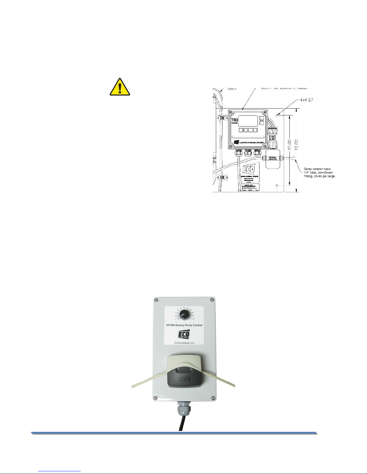
2.6 CONNECTING THE OPTIONAL CHLORINE DOSING PUMP (DPC80)
Remove the lid from the DPC80. Connect a power cord, 110 VAC, to the Line and Neutral terminals inside the
DPC 80 chlorine metering pump. Replace the lid. Mount the pump/controller near the TC80 panel. The DC80 is
supplied with 10 ft. of tubing for the peristaltic pump. Lift the Tan portion of the pump from the middle to
expose the rollers. Place the tubing into the pump and close the tan cover.
Page 19 Model TC80
Page 21
3.0 OPERATION
70
80
90
100
110
120
130
3 4 5 6 7 8 9 10 11 12 13
% Output
with pH8
= 100%
pH
TCS output vs. pH value
This section provides a basic overview of the ECD TC80 Total
Chlorine Analyzer. It covers physical and chemical influences on
the measurement and the menu structure of the analyzer.
3.01 INFLUENCES ON THE MEASUREMENT
PH VALUE
The TCS measures Total Chlorine and the total chlorine
concentration does not change with changes in the pH, there is
always the same amount of Total Chlorine. The output of the
sensor is however pH dependent, see figure 2.1, the output of the sensor decreases 5%/pH as the pH increases.
The T80 transmitter uses the pH signal from the S80 pH sensor to compensate for the decreasing output. The
measured value and the pH value are combined and the corrected Total Chlorine concentration is displayed.
The highest accuracy is attained when calibrations are performed at neutral pH values and higher chlorine
concentrations.
Figure 3.1
3.02 INFLUENCES ON THE MEASUREMENT
FLOW
The TCS consumes chlorine to produce the signal. The area near the sensing tip will become depleted of chlorine
without adequate flow to replenish the sample. The sensor requires a minimum velocity of 0.5 ft./sec past the
membrane. Below this value the sensor will indicate a lower concentration than the actual value. Higher flow
rates have little to no effect on the measurement. See Figure 3.2.
20
Page 22

0
20
40
60
80
100
0 5 10 15 20 25 30
% output
Flowrate, gal/hr
TCS Flow dependence
Figure 3.2
3.03 INFLUENCES ON THE MEASUREMENT
TEMPERATURE
The Total Chlorine Sensor (TCS) digitally outputs a temperature corrected value to the transmitter. The
temperature sensor is located in the TCS sensor and it has a response time of several minutes. Rapid changes of
temperature will introduce an error until the sensor has equilibrated to the new temperature. Calibration should
be done close to the process temperature for the highest accuracy.
Page 21 Model TC80
Page 23

3.1 KEYS
The functions associated with each key are displayed on the screen,
above the key for the Selection Adjustment Keys and to the left of
the key for the HOME and BACK keys. Press any Selection
Adjustment key twice within one second to enter the HOME Menu
Screen.
3.1.1 HOME/EXIT KEY
The HOME key performs two functions, it selects which Home
Screen is displayed and it returns the active screen to the HOME Menu Screen from anywhere inside the menu
structure.
Three Display screens are available: (Press BACK Key until a single channel is displayed then the HOME Key)
1. DATA SCREEN: Displays the measurement type, numerical value, engineering Units, % Output of the 4-
20 mA channel and temperature.
2. nA SCREEN: Displays the measurement type, the sensor’s raw nano-amp
Value, % Output of the 4-20 mA channel and temperature.
3. GRAF SCREEN: Displays a Graphical representation of the 4-20 mA channel
% Output, the measurement type, the engineering units, and temperature.
Only one of the three graphical display styles is available through the
HOME key, either the Bar, Gauge or Line display. Choose which style will
be displayed in the Graph Menu. (pathway to Graph Menu: CONFIG →
XMTR → LCD → Graph menu)
Each of the above screens also displays the condition of the optional Alarm Relays,
black if energized and white if de-energized.
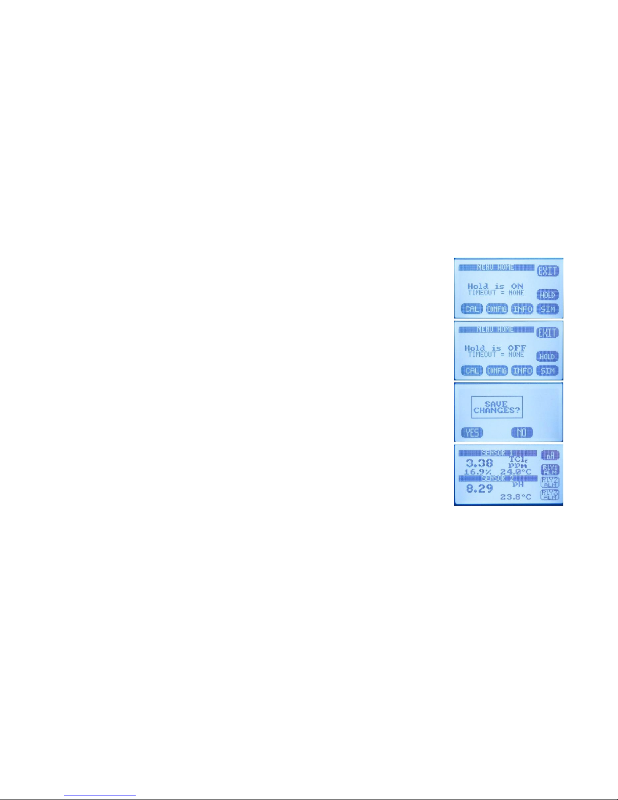
The HOME key changes to the EXIT key in the HOME Menu Screen, pressing EXIT
prompts the user to “Save Changes” YES/NO when exiting the HOME Menu. YES
applies any changes made in the menus, NO exits the HOME Menu without
applying any changes made in the menus.
3.1.2 BACK/HOLD KEY
The BACK key changes the screen to the previously displayed screen when inside a menu, it moves BACK one
screen. On a dual channel transmitter it toggles between the PV1, PV2 and Dual
Channel Screens. The HOLD key toggles the output HOLD function ON/OFF in the
MENU HOME screen.
3.1.3 SELECTION ADJUSTMENT KEYS
The (4) Selection/Adjustment keys allow navigation and numerical adjustments to
be made in the MENUs. To enter the HOME Menu screen press any of the
Selection/Adjustment keys twice within one second. The various Menu choices
and adjustment tools are displayed above the buttons once inside the MENU.
22
Page 24

3.1.4 ALPHA NUMERIC ENTRY
The LABEL and PASSWORD (Caps and Numbers only) Menus allow alphanumeric entry. Entry is accomplished by
scrolling through the alphanumeric list with the ▲ (forward) and ▼ (backwards) arrows to the character of
choice and then moving to the NEXT digit. Pressing and holding the ▲ or ▼ keys will initiate two speed auto
scrolling. The character set is sequentially listed below. The first character in the set is an empty space.
! ” # $ % & ‘ ( ) * + , - . / 0 1 2 3 4 5 6 7 8 9 : ; < = > ? @ A B C D E F G H I J K L M N O P Q R S T U V W X Y Z [ ¥ ] ^ _
‘ a b c d e f g h I j k l m n o p q r s t u v w x y z { | } → ←
3.2 MENU STRUCTURE
Double tap any Selection/Adjustment key to enter the HOME Menu Screen. Five menu choices will appear, CAL,
CONFIG, INFO, SIM and HOLD. Each of the Menus is detailed below.
3.2.1 HOLD (OUTPUT HOLD)
Pressing the HOLD Key activates the HOLD function, HOLD is ON, displayed.
Freezes the 4-20 mA output at the last value prior to activation
Freezes optional Alarm Relays in the current state
While in the HOLD mode the % Output display toggles between the last value and HOLD
Pressing HOLD again turns the hold function off, Hold is OFF, displayed. The HOLD function remains ON until it is
turned OFF. (See Time Out in CONFIG>XMTR>OUTPUT>HOLD)
3.2.2 CAL (CALIBRATION MENU)
Four options are available, AUTO, STAND, MANUAL and TEMP. On dual channel
instruments choose Sensor 1 or Sensor 2 when prompted.
The first screen asks, “Is this a New Sensor, YES / NO”. If YES the calibration history from the previous sensor is
cleared from memory and a new register is started, if NO then the calibration is written to the memory stack, (3)
sets of data are stored.
AUTO is a two point calibration. The calibration proceeds in two steps, Auto Cal 1 is an offset calibration
and Auto Cal 2 is a slope calibration. Auto Cal provides automatic solution
recognition of the calibration solutions used for each measurement in
accordance with the following list:
1. pH Calibration Buffers (US Standard), pH 4.01, pH 7.00 and pH 10.00
(see Appendix A)
2. Total Chlorine: Zero ppm (Sodium sulfite, Na
Any two solutions can be used for AUTO calibration however if solutions other than those listed above
are used for calibration then the calibration values must be entered manually.
STAND is standardization, a single point calibration. Standardizations are typically used to adjust the
process reading to agree with a laboratory determined “grab sample” reading.
MANUAL is a data entry screen. Manual calibration allows the user to enter a
concentration with the corresponding mV value and a slope for an electrode.
Laboratory generated calibration data for an electrode can be input to a
remote analyzer where calibration is difficult or impractical.
in water), Chlorinated water, DPD Tested
2SO3
Page 23 Model TC80
Page 25

TEMP allows the displayed temperature to be trimmed to agree with actual process temperature.
3.2.3 CONFIG (CONFIGURATION MENU)
Four options are available in the Configure Menu, XMTR, SENSOR, LOAD DEFAULT and Dampen.
XMTR enters the Transmitter Configuration menu.
o LCD access the Display Configuration Menu
SETUP adjust screen lighting characteristics
Temp. Choose °C or °F
CONT adjust Contrast
BACK LIGHT adjust Backlight Timeout, from always
ON to OFF after 10 minutes
GRAPH provides the choice of which Graph style is displayed
on the Home screen.
LINE , Moving average, vertical scale set to 0-100%
of the 4-20 mA output and user defined time scale
GAUGE, Current reading 0-100% of 4-20 mA range
BAR, Current reading 0-100% of 4-20 mA range
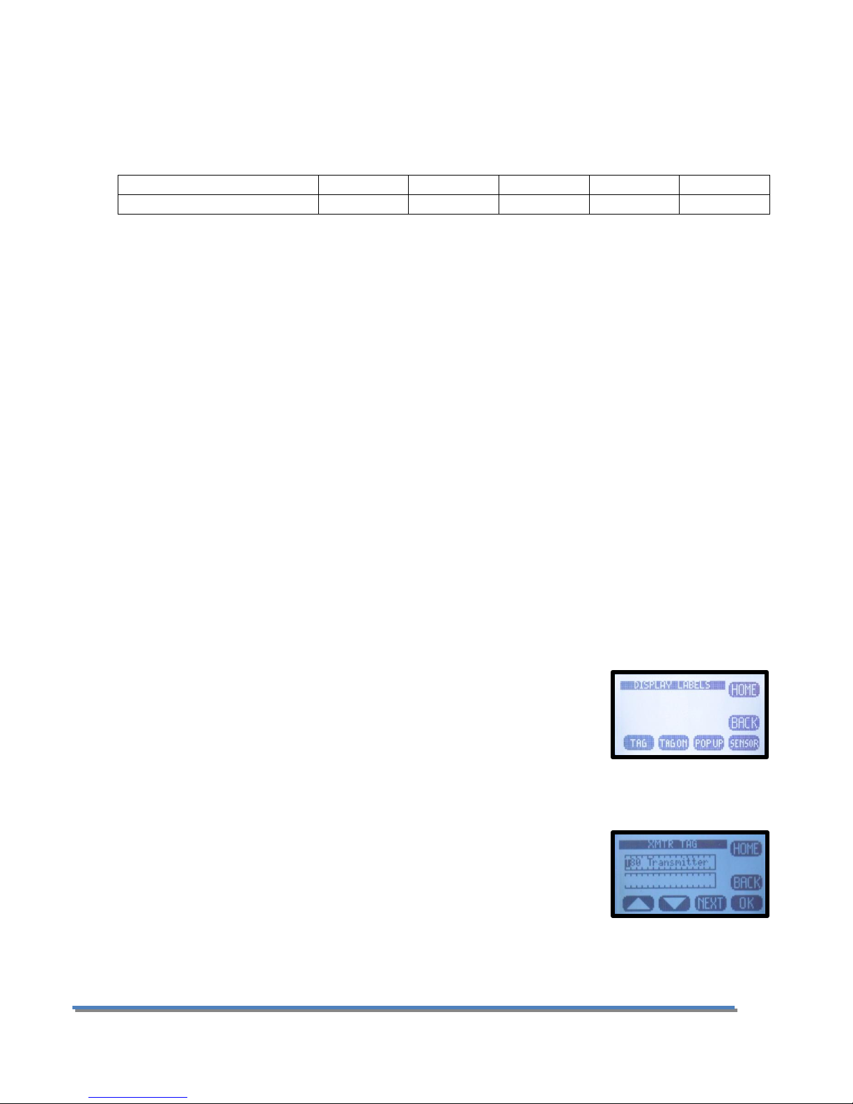
LABELS
TAG, Enter up to 2 lines x 16 characters, example,
Name, tag #... Displayed in INFO screen
TAG ON, Turn TAG ON/OFF, adds TAG to Main
Display Sequence, DATA → mV → GRAF → TAG →
DATA
POP UP, Turns ON/OFF, the double tap HOME
Screen pop up memo
SENSOR, Enter up to 2 lines x 16 characters
o OUTPUT access the Output Configuration Menu
4-20 mA configure 4-20 mA output (PV or Temp or More)
PV RANGE Enter 4 mA value and 20 mA value
Temp RANGE Enter 4 mA value and 20 mA value
MORE
o CAL Trim 4.00 mA and 20.00 mA output
o FAULT Choose fault condition 3.5 mA, 22
mA, None
RELAY
RLY1,2,3 Choose relay type:
o Alarm, enter the Set point ON, Set Point OFF, Expiration time, Delay ON
and Delay OFF times and the State, energize: changes state from deenergized to energized on alarm.
o Timed, Enter Period, Duration times and
Hold On/Off
o Fault, No input required, relay condition
changes from energize to de-energize.
24
Page 26
o Disable, Inactivates relay and removes the
relay button from the HOME Screen display.
HOLD, Freezes outputs at current value and locks relays in
their current state.
Hold Timeout, Removes HOLD after a certain period
of time, default setting: No Timeout, selections include 15 minutes, ½ hour, 1
hour
o SERIAL MODBUS configure serial output,
ADDRESS, enter address: 001 to 247
BAUD, Choose baud rate, default 9600
FORMAT, set serial data format, default value: 8N1, 8 bit, no
parity bit, 1 stop bit
o PASSWD Enter 4 character password to protect access to MENU Level, CAL Menu, CONFIG
Menu and SIM Menu (simulate). Each level can be turned ON or OFF and can have a unique
password.
MENU ON/OFF _ _ _ _ Locks Main Menu
CAL ON/OFF _ _ _ _ Locks CAL and CONFIG
CONFIG ON/OFF _ _ _ _ Locks CONFIG
SIM ON/OFF _ _ _ _ Locks SIM and CONFIG
SENSOR enters the sensor configuration menu.
o Choose SENSOR 1 or 2
TYPE, Allows T80 transmitter to configure the S80 sensor. For
use only when switching the measurement electrode type in
an S80 sensor, i.e. for a pH electrode to a pION electrode.
Select Sensor Type: pH, ORP, DO2, NH3, NH
Conductivity, Resistivity, Cu++, CN-, F-, NO
+
, Br-, Ca++, Cl-,
4
-
, K+, Ag+, Na+, S--
3
T COMP, Enter % temperature compensation per degree: pH,
0.33%, Total Chlorine 0%,
o COMP Dual Channel Only, Sets compensation type: Dissociation (pKa),
+
NH
, Free Chlorine, HF, S-2, Interference, X ppm Sensor 2 = 1 ppm
4
Sensor 1, Percentage % change per pH, Total Chlorine -5%.
o Qty of SENSORS, Choose 1 or 2
Load Default resets all Menus to factory default configuration.
Dampen, sets the number of measurements averaged for the displayed PV
3.2.4 INFO (INFORMATION MENU)
The Information Menu provides two choices,
Transmitter Screen, details the Name, Power type, Serial #, Firmware version
and the output configuration(s).
Sensor Screen, details the Name, Part #, Serial # and three sets of Calibration data.
COMP, displays the pKa, the sensor affected and the dissociation Factor,
3.2.5 SIM (SIMULATION MENU)
The Simulation menu allows the Input or Output signals to be simulated.
Page 25 Model TC80
Page 27
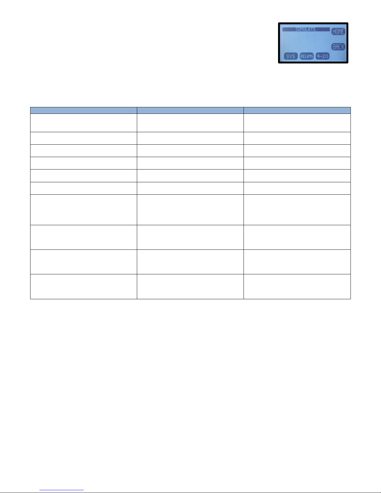
SYSTEM allows the Input to be simulated. Two choices are available, FIXED is
Fault
Definition
Recommendation
Memory Error
AN ERROR WAS FOUND
WITH THE MEMORY OF
THE MICROCONTROLLER
RETURN TO FACTORY
FOR SERVICE
Input Voltage OOT
POWER IS OUT OF
TOLERANCE
CHECK WIRING TO
THE TRANSMITTER
+12V OOT
ONBOARD 12V IS
OUT OF TOLERANCE
RETURN TO FACTORY
FOR SERVICE
+3.3V OOT
ONBOARD 3.3V IS
OUT OF TOLERANCE
RETURN TO FACTORY
FOR SERVICE
Loss of Comm
COMMUNICATION WITH
THE SENSOR WAS LOST
CHECK WIRING TO
THE SENSOR
No Sensor
NO SENSOR WAS FOUND
AT START-UP
CHECK WIRING TO
THE SENSOR
Cal Failed
SENSOR CALIBRATION
FAILED
1) CLEAN SENSING TIP
2) VERIFY SOLUTIONS
3) DO NOT LEAVE
UNATTENDED
4) RE-CALIBRATE
Relay 1 Expired
RELAY 1 TIME
ON EXPIRED
1) CHECK SENSOR OP
2) CHECK AUX EQUIP
A) PUMPS
B) TANKS
Relay 2 Expired
RELAY 2 TIME
ON EXPIRED
1) CHECK SENSOR OP
2) CHECK AUX EQUIP
A) PUMPS
B) TANKS
Relay 3 Expired
RELAY 3 TIME
ON EXPIRED
1) CHECK SENSOR OP
2) CHECK AUX EQUIP
A) PUMPS
B) TANKS
a fixed value, RAMP varies the signal across the 4-20 mA range, from the
lowest value to the highest value and back, activating and deactivating relays
if present. The RAMP has two adjustments the Ramp period, 30 seconds to 2
minutes and Duration; 1 cycle, 5, 10, 20, 30 minutes.
RELAYS allows individual relays, #1, #2, and #3 to be activated and deactivated
4-20 mA allows the output to be simulated from 4.00 mA to 20.00 mA.
3.2.6 FAULT SCREENS
3.3 OUTPUT CONFIGURATION GUIDE
Install and wire the T80 Transmitter as described in Sections 2.1 and 2.2 above.
Connect the sensor to the transmitter as described in Section 2.2 above.
Supply power to the Model T80 transmitter.
Verify the proper measurement type is displayed, pH and TCl2. The sensor automatically uploads the measured
parameter, the calibration data and the range of measurement to the transmitter. The default configuration of
the 4-20 mA output is the range of the sensor, 0-14 pH for pH sensors and 0.00 -20.00 ppm for Total Chlorine. To
change the 4-20 mA range, follow the instructions in Section 3.3.1 below.
26
Page 28

3.3.1 CONFIGURE 4-20 MA OUTPUT RANGE
Double press any key except the HOME key to enter the HOME Menu. Follow
the path below to set the 4-20 mA range.
HOME Menu → Press CONFIG → XMTR → OUTPUT → 4-20 (1)(2) → PV or
TEMP
Press CHANGE to enter New Values.
Choose 4 mA value, press OK
Enter value using ▲ or ▼and NEXT to move to the next digit, press OK→Back
Choose 20 mA value, press OK,
Enter value using ▲ or ▼and NEXT to move to the next digit, press OK→Back
Press BACK to return to the CONFIGURE 4-20 mA screen or HOME to return to
the HOME Menu screen.
3.3.2 CONFIGURE 4-20 MA FAULT CONDITION AND CAL
In the CONFIGURE 4-20 mA screen, Press MORE → FAULT or
Choose Low Fault 3.5 mA or Hi Fault 22 mA or NONE, (default setting NONE),
Press OK
Press BACK → CAL, (enter PW 0000) connect DVM to 4-20 mA line, Press 4.00
mA then adjust value to the DVM reading, Press 20.00 mA and adjust value to
the DVM reading. The 4-20 mA output is calibrated.
3.3.3 CONFIGURE ALARM RELAYS (RELAYS OPTIONAL)
HOME Menu → Press CONFIG → XMTR → OUTPUT → RELAYS→RLY1
Choose the ALARM, TIMER, FAULT or DISABLE mode for Relay 1
ALARM Displays:
o SET POINT ON: The Process Variable Value that activates the relay.
o EXPIRATION: Enter a time that should not be exceeded before the PV
should have changed enough to activate the OFF set point. At the
Expiration time the relay is deactivated and a Fault condition is
initiated. Fault: Relay 1 Time expired: Cause: Loss of reagent, failed
sensor ….
o Delay ON: The amount of time the PV must remain above/below the
set point before the relay activates.
o SET POINT OFF: The Value of the process variable that deactivates the
relay.
SET POINT OFF > Set Point → Low Set Point
SET POINT OFF < Set Point → Hi Set Point
o Delay OFF: The amount of time the PV must remain above/below the
hysteresis point before the relay deactivates.
o STATE: Energize (relay is energized on activation)/De-energize (relay
is de-energized on activation)
TIMER activates the relay periodically for a specific duration, user configured
period and duration
FAULT sets the relay condition to a de-energize state and NC relay closes in
response to a Fault condition or power failure.
Page 27 Model TC80
Page 29
DISABLE turns off the relay and removes it’s icon from the HOME screen
Setting up an Alarm Relay
Choose ALARM
Press CHANGE to enter new values
Choose ON Set Point, Press OK
Enter value using ▲ or ▼and NEXT to move to the next digit, press OK, press BACK (Min –Max values
indicate the range of acceptable values)
Choose Expiration, Press OK,
Choose time from drop down menu using ▲ or ▼, press OK, press BACK
Choose OFF Set Point, Press OK
Enter value using ▲ or ▼and NEXT to move to the next digit, press OK, press BACK
Choose Delay ON, Press OK
Enter value using ▲ or ▼and NEXT to move to the next digit, press OK, press
BACK
Choose Delay OFF, Press OK
Enter value using ▲ or ▼and NEXT to move to the next digit, press OK, and
press BACK when done to exit Relay 1.
Repeat for Relay 2 and Relay 3.
3.3.4 EXIT MENUS AND RETURN TO MAIN DISPLAY
Press HOME Key to return to the Home Menu Screen
Press Hold to turn OFF Hold
Press EXIT Key to exit the menu
“Save Changes?” press YES
Choose Display Mode, DATA, mV or GRAF by pressing selection Key. The
selection key displays which screen will be displayed next.
o The type of graphical display used, Line, Bar or Gauge is selected in
CONFIG → XMTR → LCD → GRAPH → LINE, GAUGE, BAR
3.3.5 SENSOR START UP
All sensors are supplied with protective caps over the sensing end. Remove the cap(s) from the sensor before
installing in the process. All sensors were calibrated at the factory before shipment, no calibration should be
necessary before use. Allow the sensor to equilibrate to the process solution conditions for ½ hour before
verifying the reading against a grab sample. If calibration is required follow the instruction in Section 4.0 below.
3.4 USER SELECTABLE OPTIONS
3.4.1 SCREEN LIGHTING
LED back lighting is available on AC and DC powered instruments only.
Contrast can be adjusted for optimal viewing. The Backlight can be adjusted to timeout after a set period of time
or remain on.
Location: CONFIG → XMTR → LCD → Set Up → CONT, BACK LIGHT
28
Page 30
3.4.3 GRAPHICAL DISPLAY
Full Screen Period
15 minutes
1 hour
12 hours
1 day
2 days
Sample Rate ( 1 point every)
10 seconds
40 seconds
8 minutes
15 minutes
30 minutes
There are three graphical display choices:
LINE, The Line graph is a moving average of the process variable with the 4-20 mA range as the
maximum/minimum values and a choice of time scales.
The Time scale is the amount of time displayed across the full screen. Choices include:
GAUGE, Live reading displaying 0-100% of 4-20 mA range. The Alarm Relay number(s), #1, #2 and#3
mark the respective set points on graph.
BAR, Live reading displaying 0-100% of 4-20 mA range. The Alarm Relay number(s), #1, #2 and#3 mark
the respective set points on graph.
Pressing OK after selecting a Graphical Display will exit the menu structure and return to the Main Display.
Location: CONFIG → XMTR → LCD → GRAPH
3.4.4 TAG TRANSMITTER NAME
Two 16 character lines are available for naming the transmitter, Upper and Lower case characters, Numbers and
Punctuation are available. The information entered will be displayed in the INFO screen and optionally in the
Main display sequence if activated in the TAG ON menu. The character set is listed below sequentially; the first
character in the set is an empty space.
! ” # $ % & ‘ ( ) * + , - . / 0 1 2 3 4 5 6 7 8 9 : ; < = > ? @ A B C D E F G H I J K L M N O P Q R S T U V W X Y Z [ ¥ ] ^ _
‘ a b c d e f g h I j k l m n o p q r s t u v w x y z { | } → ←
Entry is accomplished by scrolling through the alphanumeric list with the ▲ (forward →) and ▼ (backwards ←)
arrows to the character of choice and then pressing NEXT to advance the cursor to the next digit. Pressing and
holding the ▲ or ▼ keys will initiate two speed auto scrolling. Press BACK to exit the screen.
Location: CONFIG → XMTR → LCD → LABELS → TAG
3.4.5 SENSOR NAME
Two 16 character lines are available for naming the Sensor, Upper and Lower case
characters, Numbers and Punctuation are available. The information entered will
be displayed in the INFO screen. Entry is accomplished by scrolling through the alphanumeric list with the ▲
(forward →) and ▼ (backwards ←) arrows to the character of choice and then pressing NEXT to advance the
cursor to the next digit. Pressing and holding the ▲ or ▼ keys will initiate two
speed auto scrolling. Press BACK to exit the screen.
Location: CONFIG → XMTR → LCD → LABELS → SENSOR
Page 29 Model TC80
Page 31

3.4.6 PASSWORD PROTECTION
PASSWD Enter 4 character password to protect access to MENU Level, CAL Menu, CONFIG Menu and SIM Menu
(simulate). Each level can be turned ON or OFF and can have a unique password. Upper Case Characters and
Numbers are available for use.
Place the cursor in front of the level to be changed and Press OK. Move the cursor to ON and press OK to change
the password status from OFF to ON.
Entry is accomplished by scrolling through the alphanumeric list with the ▲ (forward →) and ▼ (backwards ←)
arrows to the character of choice and then pressing NEXT to advance the cursor to the next digit. Pressing and
holding the ▲ or ▼ keys will initiate two speed auto scrolling.
o MENU ON/OFF _ _ _ _ Locks Main Menu
o CAL ON/OFF_ _ _ _ Locks CAL and CONFIG
o CONFIG ON/OFF _ _ _ _ Locks CONFIG
o SIM ON/OFF _ _ _ _ Locks SIM and CONFIG
In the case of a Lost or Forgotten password enter MSTR to access the screen.
Location: CONFIG → XMTR → PSSWD
4-20 mA Calibration password “0000”
Location: CONFIG → XMTR → OUTPUT → 4-20 (1)(2) →MORE → CAL
30
Page 32
4.0 CALIBRATION
The Model T80 transmitter provides three methods of calibration:
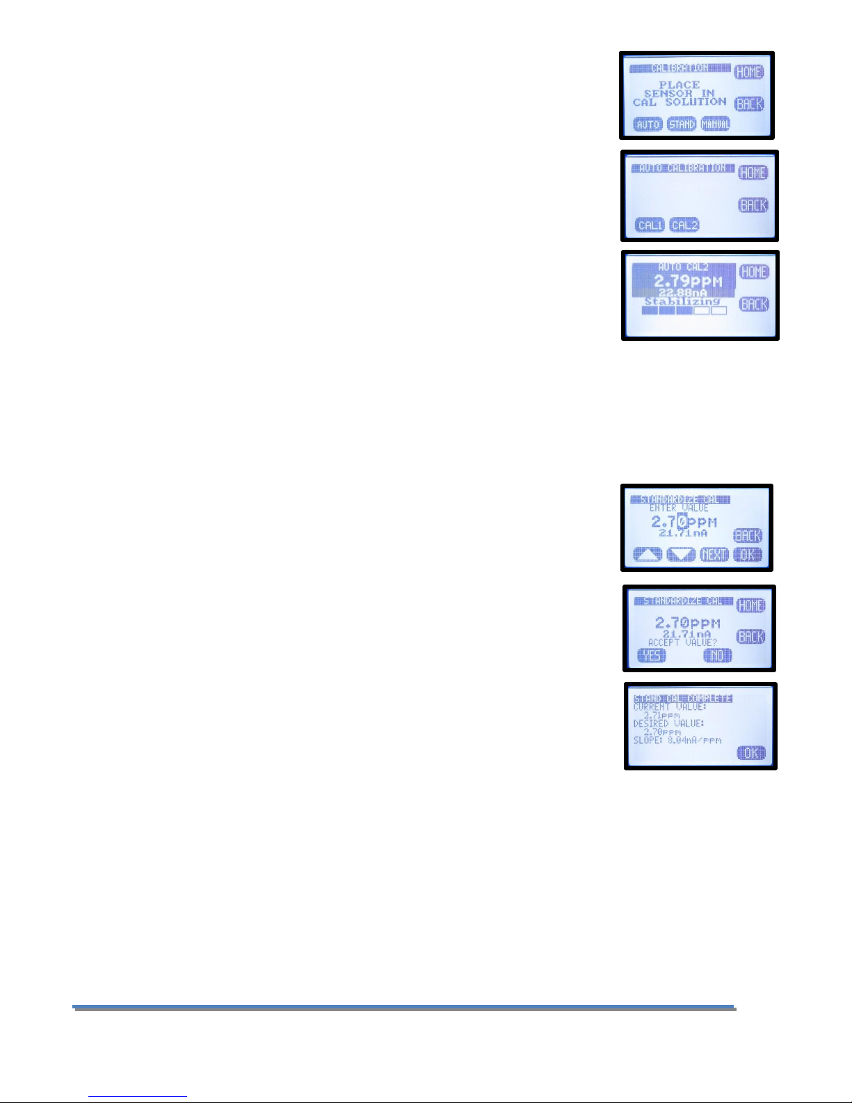
4.0.1 AUTO CALIBRATION DESCRIPTION
Auto calibration is the primary calibration method for all measurements. AUTO
calibration automatically recognizes the calibration solution the sensor is in and
proposes the actual temperature compensated value for acceptance. AUTO
calibration can be a single point or two point calibration. A single point calibration
sets the zero point or offset value of the sensor. The second calibration sets the slope
or span of the sensor.
When the AUTO key is pressed and Cal 1 or Cal2 is selected the transmitter displays
the PV (Process Variable) and the associated mV signal from the sensor. When the
reading has stabilized a calibration value is Automatically proposed, i.e. 7.00 pH, 0.00
ppm Chlorine. The user is prompted to accept the proposed calibration value or enter and accept another
value. Once Cal 1 is accepted the user is ask to continue to Cal 2, yes/no. If yes, the sensor is moved to the
second calibration solution and a second calibration value is proposed when the sensor has stabilized. Accept
the value and the calibration is complete.
At the end of each calibration the Offset and Slope are displayed in the respective units, pH, mV, ppm, Press OK
to save the calibration and write it to the sensor’s memory.
4.0.2 STANDARDIZE CALIBRATION DESCRIPTION
A Standardize Calibration is a single point calibration where the transmitter’s reading
is adjusted to agree with a solution of known value, either a calibration standard, a
grab sample or laboratory determined value. In many cases the constituents and the
pressure and temperature of the process solution are very different from the
calibration solution. In these cases, once the sensor has equilibrated to the process
environment, the Zero Point or Offset value may have shifted from the original
calibration point. Standardization allows for correction of this type of offset. It
changes the Offset value in a pH calibration. It changes the Slope value in a Chlorine
calibration. It is the primary calibration for Chlorine Sensors. Enter the Chlorine
value determined by a DPD test on the process water.
When the STAND key is pressed, the user is prompted to ENTER VALUE. The user enters the pH or Chlorine value
they want the transmitter to read and press OK. The user is then prompted to accept the value, yes/no, and the
calibration is complete. Standardizations are single point calibrations.
At the end of each calibration the Offset and Slope are displayed in the respective units, pH, mV or ppm, Press
OK to save the calibration and write it to the sensor’s memory.
4.0.3 MANUAL CALIBRATION DESCRIPTION
Manual calibration allows the user to enter calibration data for an electrode into the transmitter without
performing a calibration. A MANUAL Calibration requires the entry of three pieces of data, (1) A concentration
Page 31 Model TC80
Page 33

with the (2) corresponding mV and (3) a slope for the electrode. This allows
laboratory generated calibration data for an electrode to be entered in a remote
analyzer where calibration is difficult or impractical.
The pictures show a Manual Calibration for a Total Chlorine sensor using the default
values of 0.00 ppb = 0.00 mV and 8.0 nA/ppm.
Example: MANUAL Calibration for a pH electrode
1. Calibrate the pH electrode in the laboratory
2. Record the mV value of some pH Standard, pH 7.00 buffer = 6.8 mV (any pH –
mV pair will work)
3. Calculate and Record the slope of the electrode, 58.2 mV/pH
4. Install the electrode into the field mounted sensor
5. Press MANUAL and enter the pH value, 7.00 pH, press mV and enter the
corresponding mV value, 6.8 mV, press OK, Accept Offset?, press YES, enter
slope 58.2 mV/pH, press OK, Accept Slope?, Press YES
6. The Calibration is complete, the Offset and Slope values are displayed, press
OK to exit.
32
Page 34
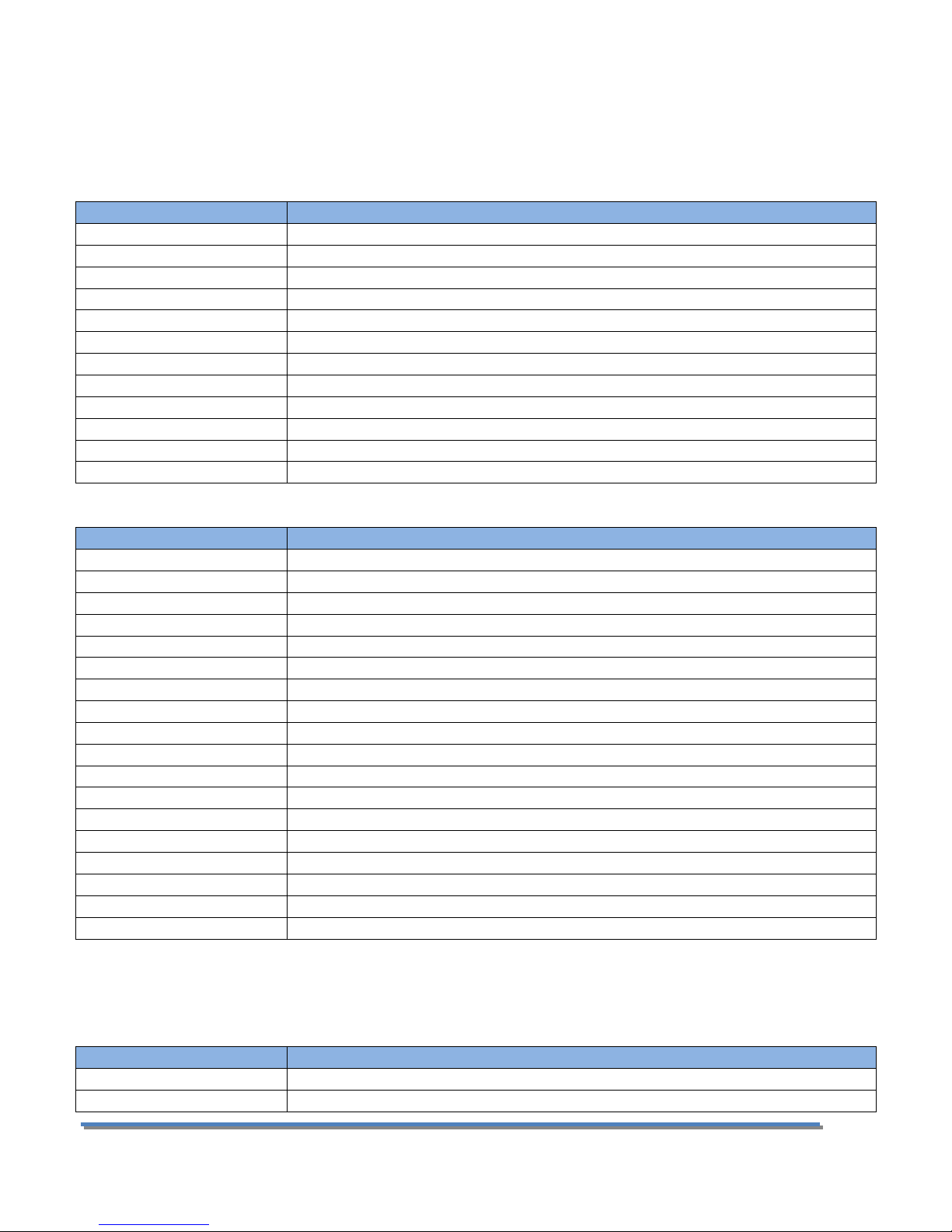
4.1 PH CALIBRATION PROCEDURES
Action
Prompt
Double Press any Button
MENU HOME, Hold is OFF
Press HOLD
Hold freezes 4-20 mA Output and locks Alarm Relays during Calibration
Press CAL
Is this a new Sensor? (Yes erases CAL Log in INFO, NO adds CAL to existing Log)
Press Yes/NO
Place Sensor in CAL Solution ( use pH 7.00 buffer)
Press AUTO then CAL 1
STABILIZING, 7.00 pH xx.x mV, 7.00 pH corrected Accept Cal 1?
Press YES
CAL1 Value 7.00 pH, Continue to CAL2? Move sensor to 4.01 pH buffer solution
Press YES
STABILIZING, 4.00 pH xxx.x mV, 4.00 pH corrected Accept Cal?
Press YES
OFFSET: 7.00 pH xx.x mV, SLOPE: 59.16 mV/pH (data written to Log)
Press OK
Calibration complete
Press HOME
Hold is ON
Press HOLD
Turn off Hold
Press EXIT
Main Display
Action
Prompt
Double Press any Button
MENU HOME, Hold is OFF
Press HOLD
Hold freezes 4-20 mA Output and locks Alarm Relays during Calibration
Press CAL
Is this a new Sensor? (Yes erases CAL Log in INFO, NO adds CAL to existing Log)
Press YES/NO
Place Sensor in CAL Solution
Press AUTO then CAL 1
STABILIZING, 6.86 pH 8.2 mV, 7.00 pH corrected Accept Cal?
Press NO
Enter CAL 1 Value
Press ▲ ▼ NEXT
6.86 pH (use arrows and NEXT to enter pH Buffer value)
Press OK
6.86 pH, 8.2 mV, Accept this Value
Press YES
CAL 1 Value 6.86 pH, Continue to CAL 2? (Place Sensor in 2nd calibration buffer)
Press YES
STABILIZING, 9.18pH 135.6 mV, 10.00 pH corrected Accept Cal?
Press NO
Enter CAL 2 Value
Press ▲ ▼ NEXT
9.18 pH (use arrows and NEXT to enter pH Buffer value)
Press OK
9.18 pH, 135.6 mV, Accept this Value
Press YES
OFFSET: 6.86 pH 8.2 mV, SLOPE: 59.16 mV/pH (data written to Log)
Press OK
Calibration complete
Press HOME
Hold is ON
Press HOLD
Turn off Hold
Press EXIT
Main Display
Action
Prompt
Double Press any Button
MENU HOME, Hold is OFF
Press HOLD
Hold freezes 4-20 mA Output and locks Alarm Relays during Calibration
AUTO Calibration recognizes pH 4.01, pH 7.00 and pH 10.00 buffer solutions for automatic, temperature
compensated calibrations. Any calibration solutions can be used but the pH value will have to be entered
manually. Follow the steps below to accomplish a pH calibration. Example uses pH 7.00 and pH 4.01 buffers.
4.1.1 AUTO CAL USING PH 4.01, 7.00, 10.00 BUFFERS
4.1.2 AUTO CAL USING OTHER PH BUFFERS
4.1.3 STANDARDIZE
Leave the sensor in the process solution, take a grab sample from the process and determine the pH or place
sensor in a calibration standard solution.
Page 33 Model TC80
Page 35

Press CAL
Is this a new Sensor? (Yes, erases CAL Log in INFO, NO adds CAL to existing Log)
Press NO
Place Sensor in CAL Solution (or leave in the process solution)
Press STAND
Enter Value
Press ▲ ▼ NEXT
xx.xx pH (use arrows and NEXT to enter process pH value)
Press OK
xx.xx pH, xxx.x mV, Accept Value?
Press YES
OFFSET: xx.xx pH x.x mV, SLOPE: xx.xx mV/pH (this data written to Log)
Press OK
Back to Cal Menu
Press HOME
Hold is ON (Press HOLD to turn off Hold)
Press HOLD
Turn off Hold
Press EXIT
Main Display
4.2 TOTAL CHLORINE CALIBRATION PROCEDURES
Action
Prompt
Double Press any Button
MENU HOME, Hold is OFF
Press HOLD
Hold freezes 4-20 mA Output and locks Alarm Relays during Calibration
Press CAL
Is this a new Sensor? (Yes erases CAL Log in INFO, NO adds CAL to existing Log)
Press Yes/NO
Place TC Sensor in CAL 1 Solution ( use 0.00 ppm solution)
Press AUTO then CAL 1
STABILIZING, 0.00 ppm, xxx.x nA, Accept Cal?
Press YES
CAL 1 Value 0.00 ppm, 0.2 nA, OK?
Press OK
Feed chlorinated water to the TC80, run DPD test when the reading stabilizes. If
the calibration times out and returns to the Home Screen, Press AUTO and select
Cal 2.
Press YES
Continue to CAL2?
Press YES
STABILIZING, 2.25 ppm, 13.2 nA, 5.00 ppm corrected, Accept Cal?
Press NO
Enter Cal 2 Value, 2.25 ppm, Change value to the DPD tested value, OK?
Press OK
OFFSET: 0.00 ppm, 0.2 nA, SLOPE: 5.86 nA/ ppm (data written to Log)
Press OK
Calibration complete
Press HOME
Hold is ON
Press HOLD
Turn off Hold
Press EXIT
Main Display
4.2.1 AUTO CAL
AUTO Calibration is an awkward calibration for the Total Chlorine sensor. It is the only way to enter the actual
zero potential of the total chlorine sensor. The Slope calibration “Cal 2” is best accomplished in the Standardized
menu, it is much easier and more straightforward.
AUTO Cal recognizes 0.00 ppm Total Chlorine solutions in Cal 1. The Zero point calibration is very consistent for
a Total Chlorine sensor and should only be done after rebuilding or replacing the sensor. To perform a zero
calibration either run chlorine free water through the flow cell or remove the sensor from the flow cell and place
it in a beaker of dechlorinated water. The zero point calibration will take about an hour for a new or rebuilt
sensor. Most sensors will burn down to a value of 0.1-0.2 mV, at this point accept the calibration and proceed to
Cal 2. Cal 2 sets the slope of the sensor. It is accomplished by setting the ppm value of the instrument to agree
with a DPD tested value of the water flowing through the TC80 Analyzer. The analyzer will suggest a corrected
value of 0.00 ppm, 5.00 ppm or 10.00 ppm, which will not be correct unless that happens to be the actual value
of the sample water, Press NO and enter the value from the DPD test. The nominal value for the slope is 5.0
nA/ppm ± 2 nA.
34
Page 36

4.2.2 STANDARDIZE
Action
Prompt
Double Press any Button
MENU HOME, Hold is OFF
Press HOLD
Hold freezes 4-20 mA Output and locks Alarm Relays during Calibration
Press CAL
Is this a new Sensor? (Yes, erases CAL Log in INFO, NO adds CAL to existing Log)
Press NO
Place Sensor in the process solution, Test sample with DPD
Press STAND
Enter Value
Press ▲ ▼ NEXT
xxx.xx ppm (use arrows and NEXT to enter process value) OK?
Press OK
xxx.xx ppm, xxx.x nA, Accept Value?
Press YES
Current Value xx.xx, Desired Value xx.xx, Change xx.xx, OK?
Press OK
Back to Cal Menu
Press HOME
Hold is ON (Press HOLD to turn off Hold)
Press HOLD
Turn off Hold
Press EXIT
Main Display
Action
Prompt
Double Press any Button
MENU HOME, Hold is OFF
Press HOLD
Hold freezes 4-20 mA Output and locks Alarm Relays during Calibration
Press CAL
Is this a new Sensor? (Yes, erases CAL Log in INFO, NO adds CAL to existing Log)
Press NO
Auto, Stand, Manual, Temp
Press MANUAL
Enter Zero Value
Press ▲ ▼ NEXT
0.00 ppm (use arrows and NEXT to enter ppm value)
Press OK
OFFSET: 0.00 ppm, 0.0 nA, Accept Value?
Press YES
Enter Slope, 5.00 nA/ppm
Press ▲ ▼ NEXT
5.00 nA/ppm
Press OK
Slope 5.00 nA/ppm, Accept this Value?
Press YES
Back to Cal Menu
Press HOME
Hold is ON (Press HOLD to turn off Hold)
Press HOLD
Turn off Hold
Press EXIT
Main Display
The Standardize Calibration is the Primary method for calibrating the Total Chlorine sensor. It is the easiest
and most straight forward method of calibration. Simply run a DPD test and enter the value in the entry screen.
4.2.3 MANUAL CAL
Manual Cal is a convenient way to reset the analyzer to default Status. Simply enter the actual zero point if it is
known or 0.00 ppm = 00.0 nA and the default slope, 5 nA/ppm and the displayed value should be in the ballpark
of the actual Total Chlorine value.
Page 35 Model TC80
Page 37

5.0 MAINTENANCE
The Model T80 transmitter requires no periodic maintenance, except to make sure the front window is kept
clean in order to permit a clear view of the display and allow proper operation of the navigation buttons. If the
window becomes soiled, clean it using a soft damp cloth or soft tissue. To deal with more stubborn stains, a
neutral detergent or spray cleaner like Windex may be used. Never use harsh chemicals or solvents.
When you open the front cover and/or cable glands, make sure that the seals are clean and correctly fitted
when the unit is re-assembled in order to maintain the housing’s NEMA 4X weatherproof integrity against water
and water vapor.
5.1 TOTAL CHLORINE SENSOR
Check the measurement versus a DPD test and visually inspect the sensor at
regular intervals, at least once a month. If the membrane is visibly soiled clean it
with a jet of water or a dilute HCl solution between 1-5%. Do not clean with
detergents or solvents that would reduce the surface tension of the membrane.
5.1.1 REMOVING OR REPLACING THE MEMBRANE
First, expose the vent hole on the cap by sliding the silicone band out of the
groove. Failure to vent the sensor before removing the cap can destroy the
membrane. Replace the membrane cap (PN 1000245-1) if heavily soiled or torn.
Remove the membrane cap by screwing it off of the body. Refill the new
membrane cap with electrolyte as described below and reinstall the cap on the
sensor.
5.1.2 POLISHING THE CATHODE
Polish the cathode when re-commissioning the sensor after storage or whenever
the membrane cap is replaced. Silver from the anode deposits on the cathode
over time and must be removed. Hold the supplied blue polishing strip on your
finger tip and with the sensor held vertically, cathode facing up, gently wipe the
strip across the cathode 2-3 times. This is an abrasive cleaning and does remove
metal from the cathode shortening the sensors life. The cathode is 24 carat gold
and after polishing it should look like 24 K gold not silvery like 10 K gold.
5.1.3 REFILLING THE SENSOR
Refill the sensor with electrolyte (PN 100246-1) every three months or sooner
depending on the chlorine level measured. The measured chlorine is reduced to
chloride inside the cell and must be periodically removed. Samples with less than 5 ppm total chlorine require
the sensor to be refilled every 3-4 months.
Lift the silicone band to Expose the vent hole and unscrew the measuring cap from the sensor. Rinse out the
spent solution with distilled water.
Fill the cap to the bottom of the threads with the gelled electrolyte and tap it gently to dislodge any trapped
bubbles inside the cap.
Screw the sensor into the measurement cap at a 45° angle ensuring all air inside the chamber is purged through
the vent hole on the side of the cap.
When the o-ring begins to seal continue slowly tightening until it hits the stop. Seal the silicone band back over
the vent hole and rinse the purged electrolyte from the sensor body with water. The sensor is ready to use, repolarize the sensor for 60 minutes before calibration.
36
Page 38

Storage
The TCS should only be stored unfilled. Expose the vent hole, remove the membrane cap, rinse out the
electrolyte with distilled water and allow the sensor to dry. Loosely reassemble the dry sensor so as not to
tension the membrane during storage.
5.2 PH SENSOR
All electrochemical sensors require periodic cleaning and/or replacement. The life of an electrode is dependent
on the process conditions it is exposed to, a pH electrode may last a year or longer in potable water and only a
few weeks in a hot caustic bath. The chemical constituents in the process may coat the electrode surfaces
requiring the electrode to be removed and cleaned or replaced.
Cleaning agents should be specific to the type of coating, detergents and alcohols for removing greases and oils,
acids for removing hard water scales and metallic deposits or spray washing for flocculants and biofilms.
5.2.1 ELECTRODE CARTRIDGE INSTALLATION
Unless ordered separately, electrode cartridges are generally shipped installed in a sensor. Sensors ordered
without an electrode are shipped with a shipping plug to keep contamination from getting inside the sensor
during shipment or storage. The following procedure explains how to install the electrode cartridge in the sensor
assembly:
1. Remove the shipping plug by turning it counterclockwise.
2. Remove the electrode cartridge from the protective soaker boot. Be careful not to flex the electrode
body while removing the tape and the protective boot.
3. Rinse the electrode tip in tap water and wipe the electrode body dry then lubricate the o-ring seals with
the included lubricant. Save the protective soaker boot in the event the electrode must be stored at a
future time.
4. Carefully insert the electrode cartridge into the sensor assembly by turning until hand tight. The first o-
ring, closest to the front of the electrode, will be slightly visible if held horizontally.
NOTE: IF EXCESS FORCE IS REQUIRED DURING ELECTRODE INSTALLATION, CHECK FOR PROPER THREAD
ENGAGEMENT OR FOR AN OBSTRUCTION.
5.2.2ELECTRODE CARTRIDGE REPLACEMENT
Periodic replacement of the electrode cartridge is required for pH, ORP and Specific Ion sensors. The following
procedure explains how to replace the electrode cartridge in the sensor assembly:
2. Remove the electrode cartridge from the front of the sensor assembly by turning it counterclockwise.
3. For installation procedure follow steps 2, 3, and 4 in section 5.2.1 electrode cartridge installation.
5.2.3 ELECTRODE CLEANING
An important aspect of sensor maintenance is the service of the electrode cartridge. After being in operation, an
electrode may begin to exhibit slow response or non-reproducible measurements. This may be due to coating of
the measurement electrode or clogging of the reference junction. Regular electrode cleaning reduces problems
Page 37 Model TC80
Page 39

associated with the coating and clogging. Frequency of cleaning will depend on the process and application. The
following procedures are used to clean pH and ORP electrodes.
If possible, the electrode should be cleaned without removing it from the sensor body. However, if the electrode
must be removed, the o-rings must be inspected and re-lubricated.
5.2.4 PH ELECTRODE CARTRIDGE CLEANING
Remove the sensor from the process and carefully wash the wetted end of the electrode cartridge in a mild
solution of detergent and water or with methyl alcohol. If the electrode response is not improved, soak the
electrode in 0.1 Molar HCl for 5 minutes. Remove and rinse the electrode with tap water and soak in 0.1 Molar
NaOH for 5 minutes.
Remove the electrode from the NaOH solution, rinse the electrode with copious amounts of tap water and soak
in a 4 pH buffer solution for 10 minutes. This should improve the response of the electrode. If not, replace the
electrode.
If the electrode must be left out of the process for an extended period of time, store it in a solution of water
saturated with KCl or a 4.0 pH buffer solution. ECD does not recommend the storage of electrodes in distilled or
deionized water.
5.3 CONSTANT HEAD FLOW CONTROLLER (CHFC)
The CHFC is designed to provide a constant flow to the Free Chlorine Sensor (FCS) independent of variations in
the sample pressure. Decreasing the sample flow to the FCS will lower the output of the FCS. In most clean
water applications the CHFC requires no maintenance. The vertical position of the central tube sets the Head
Pressure of the system. It is set for optimal flow but lower flow rates can be attained by adjusting its height.
On a monthly basis visually inspect the CHFC, the interconnecting tubing and the drain tubing for obstructions or
sediments that may reduce the flow. The CHFC and tubing can be easily disassembled and cleaned with soap
and water. Some dirty applications like Cooling Towers may require periodic cleaning due to sediments.
38
Page 40

6.0 TROUBLESHOOTING
Symptom
Possible Cause
Remedy
Displayed value is Higher
than DPD test value.
Insufficient Polarization time
Damaged Membrane Cap
pH indication higher than
actual value
Temperature indication lower
than actual value
Electrical short or wet
connection inside the sensor
or cable assembly
Polarize TCS for full 90
minutes before calibration.
Replace Membrane Cap
Calibrate pH sensor
The temperature sensor lags
the process temperature wait
for temperature equilibrium.
Remove measuring cap and
dry the cathode surface, if the
indication does not go to zero
there is leakage. Replace the
sensor.
Displayed value is Lower than
DPD test value
Displayed value is Lower than
DPD test value (cont’d)
Coated or dirty membrane
Low tension on the
membrane
Flow to low through the flow
cell
Air bubbles trapped on
membrane
Air bubble inside the sensor
between cathode and
Clean or replace the
membrane
Verify the Measuring
Chamber is fully tightened
onto the body or replace
membrane.
Clean CHFC, fittings and
tubing, verify the sample feed
rate is 10+ gal/hr.
Loosen TCS fitting and lift
sensor slightly to purge air
trapped in the flow cell.
Refill sensor, see Maintenance
The TC80 was evaluated and calibrated at the factory before shipment. Upon initial start up the system should
require minimal to no adjustments.
Verify the system has adequate flow, greater than 10 gals /hr., the pH electrode and the temperature sensor are
reading correctly. These parameters effect the measurement and must meet the standards listed in the
Calibration Section above. If these conditions are met and problems still exist use the Troubleshooting Table to
find a remedy.
Troubleshooting Guide
Page 39 Model TC80
Page 41

membrane
pH indication lower than
actual value
Temperature indication is
higher than actual value.
Calibrate pH sensor
Calibrate the Temperature
(see Calibration) The
temperature sensor lags the
process temperature wait for
temperature equilibrium.
Zero Chlorine Reading
No electrolyte in the sensor
Open Circuit on FCS, broken
or bad electrical connection
Refill Sensor
Check connector and wiring to
the connector inside the T80
Unstable Chlorine Reading
Air bubbles on the membrane
Changing temperature, the
lag of the temperature sensor
looks like drift
Loosen TCS fitting and lift
sensor slightly to purge air
trapped in the flow cell.
Wait for equilibrium
Green LED flickering or no
light
Supply Voltage to low
Defective Sensor
Verify 24V DC between the
Blue and White sensor wires
Return sensor to the
manufacturer for
reconditioning
Orange LED,
Continuously ON
Flickering
Wrong Polarity on signal
wires
Chlorine concentration to
high, sensor over range
Verify Black #3, Yel/Grn #2
Check for torn membrane,
verify chlorine concentration,
Recalibrate the sensor
40
Page 42
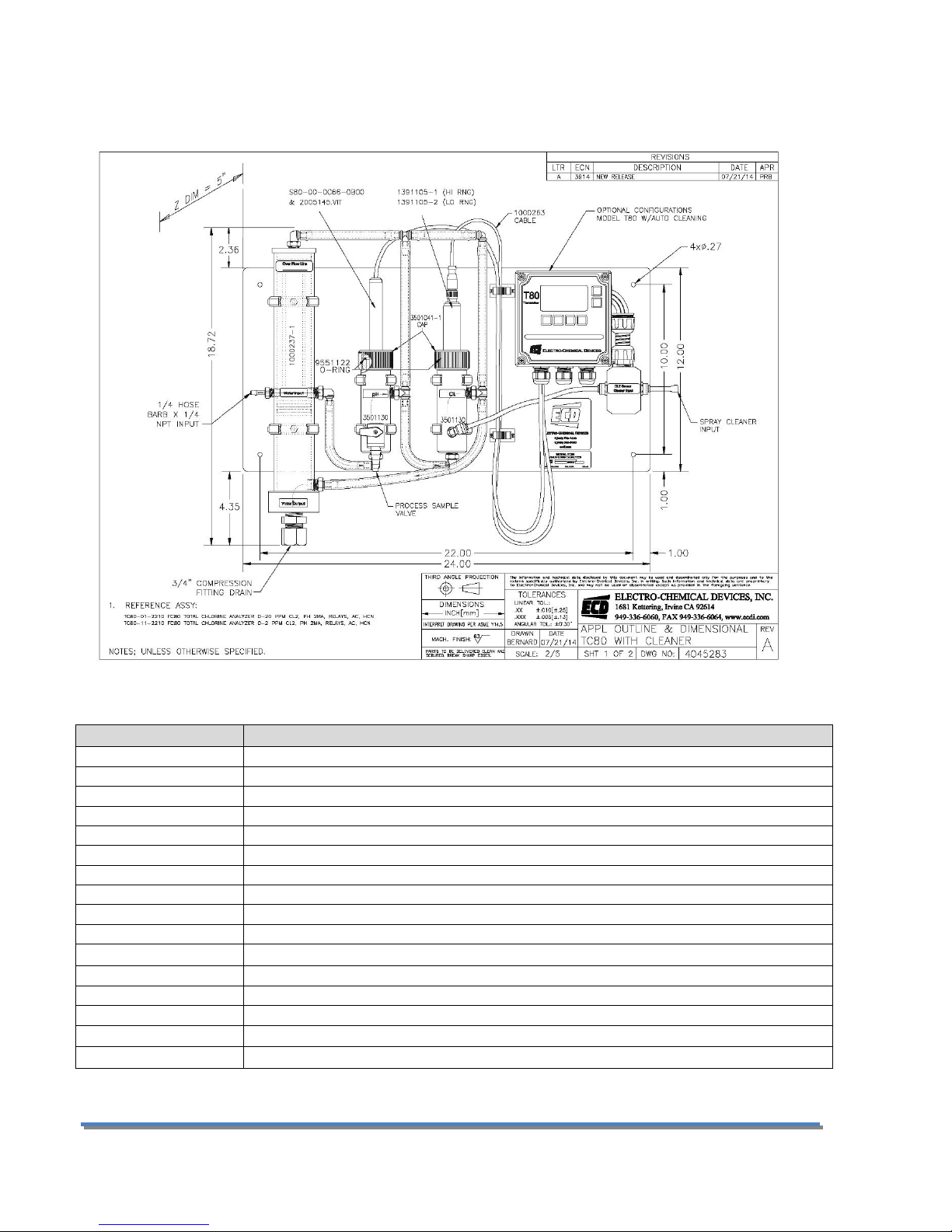
7.0 PARTS AND ACCESSORIES
Part #
Description
1391005-1
Total Chlorine Sensor, High Range, 0.5 – 20.0 ppm
1391005-2
Total Chlorine Sensor, Low Range, 0.005 – 2.00 ppm
1000248
Membrane Replacement Kit (1 membrane Cap, 50 ml bottle of electrolyte )
1000245-1
Membrane Cap Replacement (1 each)
1000246-1
Electrolyte Refill, 50 ml bottle
2005145.VIT
pH replacement electrode cartridge
S80-00-0C66-0B00
pH Sensor, 316L SS body with Flange, 4’ cable
3501131
Chlorine Flow Cell
3501130
pH Flow Cell
3501041-1
Flow Cell Threaded Cap
1000260-2
Sunshield for Rail Mount
1000237-1
Constant Head Flow Controller
1000250-1
Tube Fitting Set, complete set (9) ⅜”fittings (1) ¼” fitting
5000714-X
⅜” tubing Food Grade PVC, (X) = ft., FC80 uses 4.5 ft.
7.1 TC80 REPLACEMENT PARTS
Page 41 Model TC80
Page 43
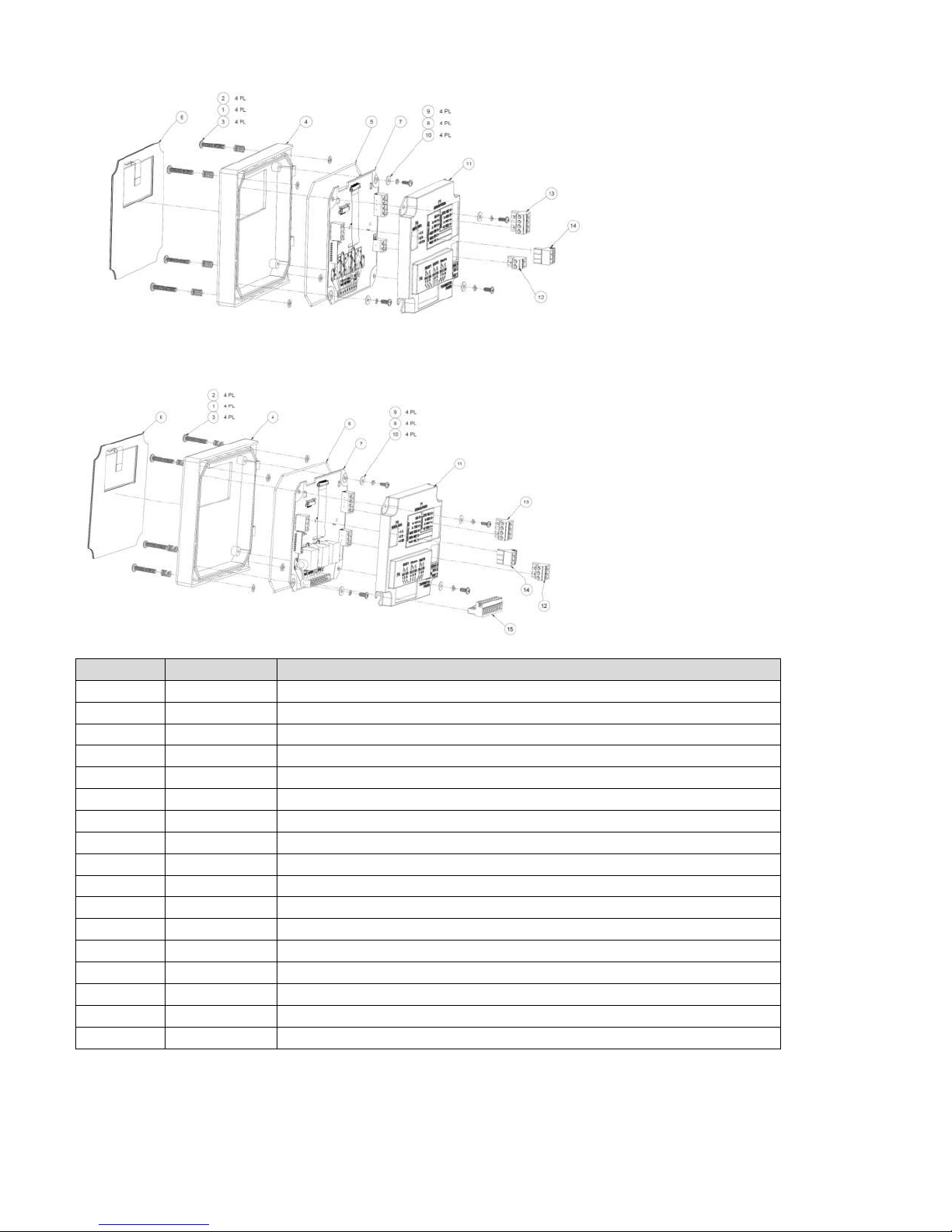
7.2 T80 FRONT PANEL CONTROL BOARD EXPLODED
Item #
Part #
Description
1
9630005
Spring, Mounting Screw Set
2
9870621
Retaining Washer, Mounting Screw Set
3
3600390
8-32 x 1” SS Screw, Mounting Screw Set
4
3400152
Front Housing
5
9560005
Sealing O-ring, grey silicone
6
9240503-1
Touch pad membrane
7
2101800-1
PCB, Control Board, Loop Powered
7
2101800-2
PCB, Control Board, Loop Powered, Relays
7
2101800-3
PCB, Control Board, Loop Powered, HART
8
9870650
Locking Washer, PCB Screw Set
9
9730905
6-32 x 5/16” SS Screw, PCB Screw Set
10
9870620
Flat Washer, PCB Screw Set
11
3400006-1
Control Board Cover
12
9090112
24 VDC, 4-20 mA Terminal Block/2 pins
13
9090114
Sensor Terminal Block/4 pins
14
9090113
Serial connection Terminal Block/3 pins
15
9090119
Relay Connection Terminal Block/9 pins
7.3 T80 FRONT PANEL CONTROL BOARD EXPLODED, WITH RELAYS
7.4 T80 TRANSMITTER CASE, BACK WITH CABLE GLANDS
42
Page 44

Item #
Part #
Description
1
3600449
Transmitter Case
2
9360005
PVC Cable Gland, ½” NPT, Grey
3
9300034
Locking Nut, ½” NPT, Steel
4
9300017
Sealing ring, ½” elastomer
5
9870650
Split Washer, PS mounting
6
9870620
Flat Washer, PS mounting
7
2101820-1
Power Supply Board
8
9730604
6-32 x ¼” screw, SS, PS mounting
7.5 T80 REPLACEMENT PARTS
Part #
Description
2000002-1
Front Panel, Loop-Powered
2000002-2
Front Panel, AC/DC Powered
2000002-3
Front Panel, Loop-Powered, Hart Output
2101820-1
Power Supply Board, 110/220 VAC Input
2101820-3
Power Supply Board, 110/220 VAC Input, w/preamp
2101820-4
Preamp Board
3400006
Control Board Cover
9090112
Connector Plug, 2 Position (Loop, AC/DC, or Hart Versions)
9090113
Connector Plug, 3 Position (Loop or AC/DC Versions)
9090114
Connector Plug, 4 Position (Loop, AC/DC or Hart Versions)
9090119
Connector Plug, 9 Position (AC/DC Version)
9240503-1
Front Panel Membrane Switch
9300017
Sealing ring, Cable Gland
9300034
Locking Nut, Cable Gland
9360005
Fitting, Cable Gland
9830214
Screw, Front Panel
Page 43 Model TC80
Page 45

APPENDIX
°C
pH
pH
pH 0 4.00
7.115
10.32
5
4.00
7.085
10.25
10
4.00
7.06
10.18
15
4.00
7.04
10.12
20
4.00
7.015
10.06
25
4.005
7.00
10.01
30
4.015
6.985
9.97
35
4.025
6.98
9.93
40
4.03
6.975
9.89
45
4.045
6.975
9.86
50
4.06
6.97
9.83
55
4.075
6.97
60
4.085
6.97
65
4.10
6.98
70
4.13
6.99
75
4.14
7.01
80
4.16
7.03
85
4.18
7.05
90
4.21
7.08
Modbus ID (Slave Address)
1 Byte
1 to 247 (0x01 to 0xF7)
Function code
1 Byte
0x03
Starting Address
2 Bytes
0x0000 to 0xFFFF
Quantity of Registers
2 Bytes
1 to 125 (0x01 to 0x7D)
CRC
2 Bytes
calculated
Modbus ID (Slave Address)
1 Byte
1 to 247 (0x01 to 0xF7)
Function code
1 Byte
0x03
Byte Count
1 Byte
2 X N*
Register Value(s)
*N X 2 Bytes
A. AUTO CAL BUFFER TABLES
B.MODBUS RTU REGISTER LISTING
03 (0X03) READ HOLDING REGISTERS
This function code is used to read the contents of a contiguous block of holding registers in a remote device.
The Request Protocol Data Unit specifies the starting register address and the number of registers. In the
Protocol Data Unit Registers are addressed starting at zero. Therefore registers numbered 1-16 are address as
0-15.
The register data in the response message are packed as to bytes per register, with the binary contents right
justified within each byte. For each register, the first byte contains the high order bits and the second contains
the low order bits.
Request
Response
44
Page 46
CRC
2 Bytes
calculated
*N = Quantity of Registers
Error
Modbus ID (Slave Address)
1 Byte
1 to 247 (0x01 to 0xF7)
Error Code
1 Byte
0x86
Exception Code
1 Byte
01, 02, 03 or 04
CRC
2 Bytes
calculated
Request
Modbus ID (Slave Address)
1 Byte
1 to 247 (0x01 to 0xF7)
Function code
1 Byte
0x06
Register Address
2 Bytes
0x0000 to 0xFFFF
Register Value
2 Bytes
0x0000 to 0xFFFF
CRC
2 Bytes
calculated
Response
Modbus ID (Slave Address)
1 Byte
1 to 247 (0x01 to 0xF7)
Function code
1 Byte
0x06
Register Address
2 Bytes
0x0000 to 0xFFFF
Register Value
2 Bytes
0x0000 to 0xFFFF
CRC
2 Bytes
calculated
*N = Quantity of Registers
Error
Modbus ID (Slave Address)
1 Byte
1 to 247 (0x01 to 0xF7)
Error Code
1 Byte
0x86
Exception Code
1 Byte
01, 02, 03 or 04
CRC
2 Bytes
calculated
Name
Meaning (2 bytes each register)
Number
of
Registers
Return
Data
Format
Read
Write
Requires
Storage
Initiate
Register #
dec
hex
Modbus ID (slave address)
Defined as 1 to 247 per the Modbus Application
Protocol Specification (V1.1b)
1
16 bit
Integer
RW 0
00
Data Format
Data Format of the User Bus to the T80 (0-DF8N2, 1-
DF8O1, 2-DF8E1, 3-DF8N1)
1
16 bit
Integer
RW 1
01
Baud Rate
Baud Rate of the User Bus to the T80 (0-1200, 1-
2400, 2-4800, 3-9600)
1
16 bit
Integer
RW 2
02
BusMessage
total message count detected by the slave (remote
device)
1
16 bit
Integer
R 3
03
BusCommunicationsError
total CRC error count
1
16 bit
Integer
R 4
04
06 (0X06) WRITE SINGLE REGISTER
This function code is used to write a single holding register in a remote device.
The Request Protocol Data Unit specifies the address of the register to be written. Registers are addressed
starting at zero. Therefore register number 1 is addressed as 0.
The normal response is an echo of the request, returned after the register contents have been written.
REGISTERS
Per the Modbus Application Protocol Specification (V1.1b)
Page 45 Model TC80
Page 47

SlaveExceptionError
total count of exceptions detected
1
16 bit
Integer
R 5
05
SlaveMessage
total messages addressed to the slave (remote
device)
1
16 bit
Integer
R 6
06
SlaveNoResponse
total count of messages not responded to by the
slave (remote device)
1
16 bit
Integer
R 7
07
SlaveNAK
total Negative Acknowledges returned by slave
(remote device)
1
16 bit
Integer
R 8
08
SlaveBusy
total count of "slave busy" was returned for an
address message
1
16 bit
Integer
R 9
09
BusCharacterOverrun
count of messages that couldn't be handled due to
character over-run condition
1
16 bit
Integer
R 10
0A
Reset all Modbus Error
Counters
Resets all of the Modbus Error counters (defined in
Modbus spec) to 0, Write any value.
1
16 bit
Integer
W 11
0B
Product T80 Model Number
(Modbus)
The Model Number of the Unit polled
1
16 bit
Integer
R 12
0C
T80 Serial Number (hi word)
Unit Serial Number (32 bit integer hi word, bytes 3
and 2)
2
32 bit
Long
Integer
R
13
0D
T80 Serial Number (lo word)
Unit Serial Number (32 bit integer lo word, bytes 1
and 0)
14
0E
T80 Mode
Unit operating mode (1-Startup, 2-Sensor Search, 3-
Operate)
1
16 bit
Integer
R 15
0F
T80 Fault Status
Unit Fault flags, bit defined
1
16 bit
Integer
R 16
10
T80 2nd Fault Status
Unit Fault flags (2nd word reserved, currently not
used)
1
16 bit
Integer
R 17
11
T80 Warning Status
Unit Warning flags, bit defined
1
16 bit
Integer
R 18
12
T80 2nd Warning Status
Unit Warning flags (2nd word reserved, currently not
used)
1
16 bit
Integer
R 19
13
T80 FW Rev
Firmware revision of the Control BD in ASC, ex. " 1".
1
16 bit
Integer
R 20
14
Relay Number to read/write
Relay number to access data (0 - Relay 1, 1 - Relay 2,
2 - Relay 3)
1
16 bit
Integer
RW 21
15
Relay Type
Read/Write Relay Type (0 - Fault Type, 1 - Alarm
Type, 2 - Disabled, 3 - Timed)
1
16 bit
Integer
RW Y 22
16
Relay ON Setpoint (hi word)
Read/Write Relay ON Setpoint (byte 3 and byte 2)
2
32 bit
Floating
Point
RW
Y
23
17
Relay ON Setpoint (lo word)
Read/Write Relay ON Setpoint (byte 1 and byte 0)
24
18
Relay OFF Setpoint (hi
word)
Read/Write Relay OFF Setpoint (byte 3 and byte 2)
2
32 bit
Floating
Point
RW
Y
25
19
Relay OFF Setpoint (lo
word)
Read/Write Relay OFF Setpoint (byte 1 and byte 0)
26
1A
Relay ON Delay (hi word)
Read/Write Relay turn on Delay time (byte 3 and
byte 2)
2
32 bit
Floating
Point
RW
Y
27
1B
Relay ON Delay (lo word)
Read/Write Relay turn on Delay time (byte 1 and
byte 0)
28
1C
Relay OFF Delay (hi word)
Read/Write Relay turn off Delay time (byte 3 and
byte 2)
2
32 bit
Floating
Point
RW
Y
29
1D
Relay OFF Delay (lo word)
Read/Write Relay turn off Delay time (byte 1 and
byte 0)
30
1E
Relay Energized State
Read/Write Relay 0 - Energized, 1 - De-Energized
1
16 bit
Integer
RW Y 31
1F
Relay Expiration
Read/Write Expiration Time, used with alarm type (0
- None, 2 - 5min., 3 - 10min., 4 - 15min., 6 - 30min.)
1
16 bit
Integer
RW Y 32
20
Relay Period
Read/Write Timed Relay Period (0 - 15min., 1 -
30min., 2 - 1hr., 3 - 2hr., 4 - 4hr., 5 - 8hr., 6 - 24hr.)
1
16 bit
Integer
RW Y 33
21
Relay Duration
Read/Write Timed Relay Duration (0 - 15sec., 1 30sec., 2 - 1min., 3 - 2min., 4 - 5min., 5 - 15min., 6 10min.)
1
16 bit
Integer
RW Y 34
22
46
Page 48

Relay Hold Time
Read/Write Timed Relay Hold Time (0 - Off, 1 - held
for the duration time, 2 - duration + 15sec., 3 - duration
+ 30sec., 4 - duration + 1min., 5 - duration + 2min., 6 duration + 5 min., 7 - duration + 15min., 8 - duration +
30min.)
1
16 bit
Integer
RW Y 35
23
4-20 mA Channel Number to
read/write
4-20 mA channel number to access data (0 - 1st 420mA, 1 - 2nd 4-20)
1
16 bit
Integer
RW Y 36
24
4-20 Analog Type
Read/Write 4-20 Type (0 - Range, 1 - Temperature, 2
- Sentinel)
1
16 bit
Integer
RW Y 37
25
4-20 Analog Range, 4mA
range (hi word)
Read/Write 4mA range (bytes 3 and 2) applies to
both range and temperature types
2
32 bit
Floating
Point
RW
Y
38
26
4-20 Analog Range, 4mA
range (lo word)
Read/Write 4mA range (bytes 1 and 0) applies to
both range and temperature types
39
27
4-20 Analog Range, 20mA
range (hi word)
Read/Write 4mA range (bytes 3 and 2) applies to
both range and temperature types
2
32 bit
Floating
Point
RW
Y
40
28
4-20 Analog Range, 20mA
range (lo word)
Read/Write 4mA range (bytes 1 and 0) applies to
both range and temperature types
41
29
Long Tag Line number to
read/write
Tag Line number to access data (0 - Line 1, 1 - Line 2)
1
16 bit
Integer
RW Y 42
2A
Long Tag Line 1 (16
characters max)
ASCII character bytes 0 and 1, ex. "AB" A - 65 (41
hexadecimal), B - 66 (42 hex), send 6566 (4142 hex).
The characters permitted are space ' ' (32 base 10, 20
hex) through '}' 125 base 10, 7D hex).
1
16 bit
Integer
RW Y 43
2B
Long Tag Line
ASCII bytes 2 and 3
1
16 bit
Integer
RW Y 44
2C
Long Tag Line
ASCII bytes4 and 5
1
16 bit
Integer
RW Y 45
2D
Long Tag Line
ASCII bytes 6 and 7
1
16 bit
Integer
RW Y 46
2E
Long Tag Line
ASCII bytes 8 and 9
1
16 bit
Integer
RW Y 47
2F
Long Tag Line
ASCII bytes 10 and 11
1
16 bit
Integer
RW Y 48
30
Long Tag Line
ASCII bytes 12 and 13
1
16 bit
Integer
RW Y 49
31
Long Tag Line
ASCII bytes 14 and 15
1
16 bit
Integer
RW Y 50
32
Initiate T80 Parameter
Storage
Signals the user has completed entering the data and
wants it stored. Write any value.
1
16 bit
Integer
RW 51
33
Sensor Channel to
read/write
Sensor channel number to access data (0 - Sensor 1,
1 - Sensor 2)
1
16 bit
Integer
RW 52
34
S80 Mode
Unit operating mode (0-
1
16 bit
Integer
R 53
35
S80 Serial Number (hi word)
Unit Serial Number (32 bit integer hi word)
2
32 bit
Long
Integer
R
54
36
S80 Serial Number (lo word)
Unit Serial Number (32 bit integer lo word)
55
37
S80 Fault Status
1
16 bit
Integer
R 56
38
S80 Sensor Type
Specific S80 sensor type (see S80 Sensor Types tab)
1
16 bit
Integer
R 57
39
S80 Sensor Chemical Type
Specific chemicals the S80 is set to detect (see S80
Sensor Types tab)
1
16 bit
Integer
RW Y 58
3A
S80 Max Range (hi word)
Max sensor range (bytes 3 and 2)
2
32 bit
Floating
Point
R
59
3B
S80 Max Range (lo word)
Max sensor range (bytes 1 and 0)
60
3C
S80 Min Range (hi word)
Min sensor range (bytes 3 and 2)
2
32 bit
Floating
Point
R
61
3D
S80 Min Range (lo word)
Min sensor range (bytes 1 and 0)
62
3E
S80 Sensor Value (hi word)
Current sensor value (bytes 3 and 2)
2
32 bit
Floating
Point
R
63
3F
S80 Sensor Value (lo word)
Current sensor value (bytes 1 and 0)
64
40
S80 Sensor Voltage (hi
word)
Corresponding sensor voltage to the sensor value
(byte 3 and byte 2)
2
32 bit
Floating
Point
R
65
41
Page 47 Model TC80
Page 49

S80 Sensor Voltage (lo
word)
Corresponding sensor voltage to the sensor value
(byte 1 and byte 0)
2
32 bit
Floating
Point
R 66
42
S80 Sensor Temperature (hi
word)
Sensor Temperature (bytes 3 and 2)
2
32 bit
Floating
Point
R
67
43
S80 Sensor Temperature (lo
word)
Sensor Temperature (bytes 1 and 0)
68
44
S80 Sensor is a Sentinel
Sensor is a Sentinel Type (0 - No, 1 - Yes)
1
16 bit
Integer
R 69
45
S80 Sentinel Life %
% of Sensor life remaining
1
16 bit
Integer
R 70
46
S80 Sentinel Vs (hi word)
Scaled Sentinel Voltage (in mV) normalized to Vo
(bytes 3 and 2)
2
32 bit
Floating
Point
R
71
47
S80 Sentinel Vs (lo word)
Scaled Sentinel Voltage (in mV) normalized to Vo
(bytes 1 and 0)
72
48
S80 Sentinel Vo (hi word)
Sentinel 100% value (in mV) on the life relative to 0V
(bytes 3 and 2)
2
32 bit
Floating
Point
RW
Y
73
49
S80 Sentinel Vo (lo word)
Sentinel 100% value (in mV) on the life relative to 0V
(bytes 1 and 0)
74
4A
S80 Sentinel Range (hi word)
Sentinel Range (bytes 3 and 2)
2
32 bit
Floating
Point
RW
Y
75
4B
S80 Sentinel Range (lo word)
Sentinel Range (bytes 1 and 0)
76
4C
Sensor Full Name (18
characters max)
ASCII character bytes 0 and 1, ex. "AB" A - 65 (41
hexidecimal), B - 66 (42 hex), send 6566 (4142 hex).
The characters permitted are space ' ' (32 base 10, 20
hex) through '}' 125 base 10, 7D hex).
1
16 bit
Integer
RW Y 77
4D
Sensor Full Name
ASCII bytes 2 and 3
1
16 bit
Integer
RW Y 78
4E
Sensor Full Name
ASCII bytes 4 and 5
1
16 bit
Integer
RW Y 79
4F
Sensor Full Name
ASCII bytes 6 and 7
1
16 bit
Integer
RW Y 80
50
Sensor Full Name
ASCII bytes 8 and 9
1
16 bit
Integer
RW Y 81
51
Sensor Full Name
ASCII bytes 10 and 11
1
16 bit
Integer
RW Y 82
52
Sensor Full Name
ASCII bytes 12 and 13
1
16 bit
Integer
RW Y 83
53
Sensor Full Name
ASCII bytes 14 and 15
1
16 bit
Integer
RW Y 84
54
Sensor Full Name
ASCII bytes 16 and 17
1
16 bit
Integer
RW Y 85
Sensor Abbreviated Name (8
characters max)
ASCII character bytes 0 and 1, ex. "AB" A - 65 (41
hexidecimal), B - 66 (42 hex), send 6566 (4142 hex).
The characters permitted are space ' ' (32 base 10, 20
hex) through '}' 125 base 10, 7D hex).
1
16 bit
Integer
RW Y 86
56
Sensor Abbreviated Name
ASCII bytes 2 and 3
1
16 bit
Integer
RW Y 87
57
Sensor Abbreviated Name
ASCII bytes 4 and 5
1
16 bit
Integer
RW Y 88
58
Sensor Abbreviated Name
ASCII bytes 6 and 7
1
16 bit
Integer
RW Y 89
59
Initiate S80 Storage
Signals the user has completed entering the data and
wants it stored. Write any value.
1
16 bit
Integer
W 90
5A
Cal log number to read
Cal log number to read (0 - Cal Log 1, 1 - Cal Log 2, 2 Cal Log 3)
1
16 bit
Integer
RW 91
5B
S80 Cal Log slope (hi word)
(bytes 3 and 2)
2
32 bit
Floating
Point
R
92
5C
S80 Cal Log slope (lo word)
(bytes 1 and 0)
93
5D
S80 Cal Log offset (hi word)
(bytes 3 and 2)
2
32 bit
Floating
Point
R
94
5E
S80 Cal Log offset (lo word)
(bytes 1 and 0)
95
5F
S80 Cal Log offset Voltage
(hi word)
(bytes 3 and 2)
2
32 bit
Floating
Point
R
96
60
S80 Cal Log offset Voltage
(lo word)
(bytes 1 and 0)
97
61
48
Page 50
FAULT STATUS
Bit #
bit meaning
0
Memory Error, either a Program Flash, RAM or NVM RAM checksum error has occurred
1
Input Voltage Out Of Tolerance
2
The On Board +12V is Out of Tolerance
3
The On Board +3.3V is Out of Tolerance
4
The Transmitter has lost communication link with the Sensor
5
There is no Sensor connected
6
Sensor Calibration Failed
7
Relay 1 on-time expired
8
Relay 2 on-time expired
9
Relay 3 on-time expired
10
Sentinel Error (useable life has expired)
11
Sentinel Poisoned
12
Membrane Error
13
NU
14
NU
15
NU
Bit #
bit meaning
0
The Sensor has changed from previously connect Sensor
1
Not Used (NU)
2
NU
3
NU
4
NU 5 NU 6 NU
7
NU
8
NU
9
NU
10
NU
11
NU
12
NU
13
NU
14
NU
15
NU
Data
Meaning
Decimal
Hexadecimal
Chemical
Sensor Type
Measurement
Units
0
0000
Unknown
Chemical
None
None
1
0001
Ammonia
mV
ppm
2
0002
Ammonium
mV
ppm
3
0003
Bromide
mV
ppm
4
0004
Calcium
mV
ppm
5
0005
Chloride
mV
ppm
6
0006
Conductivity
Conductivity
S
7
0007
Cupric
mV
ppm
8
0008
Cyanide
mV
ppm
9
0009
DO
mV
ppm
10
000A
DO
mV
% saturation
11
000B
DO
mV
mg/L
WARNING STATUS
SENSOR TYPE
Page 49 Model TC80
Page 51

12
000C
Fluoride
mV
ppm
13
000D
Hardness (CaCO₃)
mV
ppm
14
000E
Nitrate
mV
ppm
15
000F
ORP
mV
mVa
16
0010
pH
mV
none
17
0011
Potassium
mV
ppm
18
0012
Resistivity
Conductivity
Ohm (W)
19
0013
Silver
mV
ppm
20
0014
Sodium
mV
ppm
21
0015
Sulfide
mV
ppm
22
0016
Turbidity
TR6
FNU
23
0017
Turbidity
TR6
NTU
24
0018
Turbidity
TR6
ppm
25
0019
Turbidity
TR6
mg/L
26
001A
Turbidity
TR6
% solid
27
001B
DO
DO80
ppm
28
001C
DO
DO80
% saturation
29
001D
DO
DO80
mg/L
30
001E
Calcium
mV
mg/L
31
001F
TDS
Conductivity
ppm
32
0020
Nitrite
mV
ppm
33
0021
TC (max range)
TC80
mg/L
34
0022
TC (min range)
TC80
mg/L
35
0023
FC (max range)
FC80
mg/L
36
0024
FC (min range)
FC80
mg/L
C. AUTO SPRAY CLEANER
The TC80 is available with an automatic spray cleaner. The cleaning cycle is controlled by Alarm Relay 1 which is
configured as a TIMED relay. The default settings are a 12 hour period, 30 second duration and the HOLD
function ON for the duration plus 1 minute. The relay actuates a solenoid that feeds high pressure air or water
to the chlorine flow cell. The turbulence blasts away any biofilms or soft precipitating coatings from the sensors,
flow cells and lines. The greatest turbulence is in the Chlorine flow cell but both flow cells are agitated as are the
feed lines. The duration and period of the cleaning cycle can be easily adjusted to suit the needs of the
installation. (See section 3.3.3 Configuring Alarm Relays)
1. Remove the ¼” polypropylene tube from the John Guest fitting on the right side of the solenoid
cleaner enclosure.
2. Provide 20-40 psi water or air to the ¼” John Guest fitting.
50
Page 52

ADENDUM: DC80 DE-CHLORINATION ANALYZER
The following two paragraphs were extracted from “EPA Wastewater Technology Fact Sheet Dechlorination,”
EPA 832-F-00-022
At present, few options exist for reliable long-term measurement of sulfite salts or closeto-zero levels of residual chlorine in the finished effluent (ASCE and WEF, 1991). In
recent practice, the only viable method for continuous residual chlorine measurement has
been the amperometric technique, but this suffers from loss of accurate calibration at low
concentrations (Finger et al., 1985)…. For these reasons, control of dechlorination—
particularly dechlorination to zero residual—has been problematic. Treatment plant
operators have had to work around this limitation using various control strategies.
One commonly used strategy is the use of a “zero shifted” or “biased” analyzer (WEF,
1996; Nagel, 1994). In this scheme, a residual chlorine analyzer is used and a known
concentration, X, of chlorine is added to the effluent sample to be analyzed. In this
technique, the “zero” point is shifted by the value of X, and residual chlorine or sulfur
dioxide can be inferred from the result of sample analysis.
The ECD Model DC80 De-Chlorination Analyzer uses the “zero shifted” strategy. The TC80 Total chlorine
Analyzer is fitted with a chlorine dosing pump that feeds into the outfall of the Constant Head Flow Controller
and an “Offset” feature to accomplish the “zero point shift”.
Page 51 Model TC80
Page 53

DC80 START UP PROCEDURES
Complete all Installation steps in Section 2 INSTALLATION. This includes mounting the panel, supplying power,
wiring the outputs and filling and installing the sensors. The DC80 was calibrated at the factory before shipping
as described in Section 4.2.
The Chlorine dosing pump is designed to supply approximately 5 ppm of chlorine to the measurement system
using a 10:1 dilution of standard household bleach, 6-8% sodium hypochlorite. The peristaltic pump speed is
scaled 0-100 with 40-50 providing the optimal speed to supply 5 ppm. The speed setting of 50 uses 1 liter of
diluted chlorine solution per day. That equates to 3 days and 21 hours per gallon of solution, 5 gallons is 19 days.
Dilute a volume of bleach and place it in an opaque plastic container. Protect the diluted solution from light.
Light degrades chlorine, turning it into sodium chloride. Insert the 4mm (0.167”) tubing from the peristaltic
pump into the bleach solution. It is best to drill a hole in the containers cap slightly larger than 4mm to keep the
tubing in place and to allow air to enter as the solution is pumped out.
Supply chlorinated water to the TC80 and allow the reading to stabilize for at least 2 hours. The analyzer should
display some non-zero value, 1-3 ppm is a good range. When the reading has stabilized record the reading and
start the chlorine feed by setting the pump speed to 50. It will take a minute or two for the chlorine to reach the
injection point. The reading will jump up to around 5 ppm + the 1-3 ppm background value. Adjust the pump
speed to generate a chlorine level exactly 5 ppm higher than the background value.
Remove the chlorinated sample stream from the TC80 and connect the dechlorinated water to the Constant
Head Flow Controller. The Analyzer will display a value near 5 ppm, higher if chlorine is present in the sample
stream or lower if sulfite is in excess.
To use the OFFSET feature go to MENU > CONFIG > MORE > OFFSET. Enter -5 ppm or negative whatever ppm
value you are adding, press OK > HOME > EXIT > SAVE > YES. The analyzer will now display 0.00 ppm plus any
chlorine present or –X.XX ppm if the reducing agent (sulfite) is in excess.
52
 Loading...