


CA6
Table of contents
 Loading...
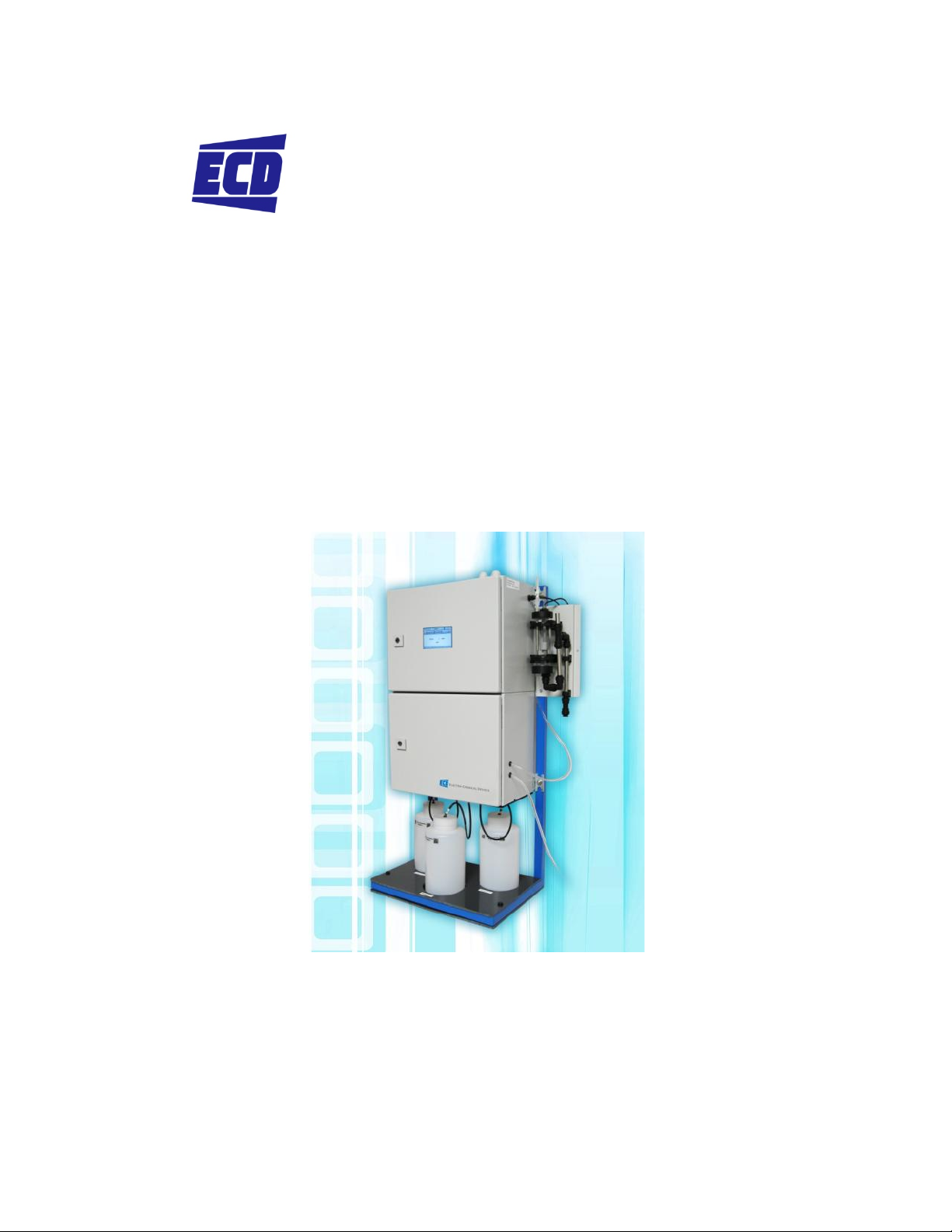
The information and technical data disclosed in this document may be used and disseminated only for the purpos es and to the
ELECTRO-CHEMICAL DEVICES
Instruction Manual
Model CA-6 Analyzer
Hardness
extent specifically authorized in writing by Electro-Chemical Devices. Electro-Chemical Devices reserves the right to change
published specifications and designs without prior notice.
Rev: B– 10/14

PREFACE
Purchasing products from Electro-Chemical Devices, Inc. provides you with the finest liquid analytical
instrumentation available. If this is your first purchase from ECD, please read this manual before
installing and commissioning your new equipment.
If there are any questions concerning this equipment, please contact your local ECD representative, or
the factory directly at:
Electro-Chemical Devices, Inc.
1681 Kettering
Irvine, CA 92887 USA
Telephone: +1-949-336-6060
FAX: +1-949-336-6064
Website: www.ecdi.com
Email: sales@ecdi.com
© 2014 Electro-Chemical Devices, Inc. All rights reserved. No part of this manual may be used or reproduced in any form or by any means, or
stored in a database or retrieval system without prior written permission from Electro-Chemical Devices, Inc. Making copies of any part of this
manual for any purpose other than personal use is a violation of United States copyright laws. Document printed in the United States of
America.
CA-6 Analyzers Page ii

TABLE OF CONTENTS
PREFACE ........................................................................................................................................................ ii
TABLE OF CONTENTS .................................................................................................................................... iii
TERMS AND CONDITIONS OF SALE ............................................................................................................. vii
RETURNED GOODS POLICY ........................................................................................................................... x
IMPORTANT SERVICE INFORMATION .......................................................................................................... xi
UNPACKING THE INSTRUMENT.................................................................................................................... xi
1.0 OVERVIEW ............................................................................................................................................... 1
CONTENTS: ................................................................................................................................................ 1
1.0.1 CA-6 Technical Specifications ....................................................................................................... 2
1.1 Safety Precautions, Instructions and Hazards .................................................................................... 3
1.1.1 General information ..................................................................................................................... 3
1.1.2 List of warnings and potential dangers ........................................................................................ 3
1.1.3 Reagents ....................................................................................................................................... 4
1.1.4 Sample Stream ............................................................................................................................. 5
1.1.5 Waste disposal of the liquid reagents for the colorimetric reaction ........................................... 5
1.1.6 Analyzer General Hazards ............................................................................................................ 5
2.0 INTRODUCTION – Analyzer Description .................................................................................................. 7
2.1 Applications ........................................................................................................................................ 7
2.2 Working principle: Lambert-Beer law ................................................................................................. 7
2.2.1 Absorption photometry (Colorimetry): ........................................................................................ 8
2.3 Analysis Cycle ...................................................................................................................................... 9
2.3.1 Typical Run Sequence: ................................................................................................................. 9
2.3.2 Settings ....................................................................................................................................... 10
2.3.3 Programmable Functions ........................................................................................................... 11
2.4 Components ...................................................................................................................................... 15
2.4.1 Fast-loop reservoir ..................................................................................................................... 15
2.4.2 Sampling Pump .......................................................................................................................... 16
2.4.3 3 Way Valve ................................................................................................................................ 16
2.4.4 Micro Peristaltic Pumps ............................................................................................................. 16
2.4.5 Mixing Pump .............................................................................................................................. 16
CA-6 Analyzers Page iii

2.4.6 Pinch Valve ................................................................................................................................. 16
2.4.7 Colorimetric Reaction Cell .......................................................................................................... 17
2.4.8 Sample Drain .............................................................................................................................. 17
2.4.9 Electronic Components .............................................................................................................. 17
3.0 OPTIONS ................................................................................................................................................ 18
3.1 Dilution Module ................................................................................................................................ 18
3.2 Oxidation/Digestion Module ............................................................................................................. 19
4.0 INSTALLATION ........................................................................................................................................ 21
4.1 Unpacking and Inspecting ................................................................................................................. 21
4.2 Analyzer Handling ............................................................................................................................. 21
4.3 Location and Mounting Instructions ................................................................................................. 21
4.4 Pre-Installation .................................................................................................................................. 21
4.5 Electrical Connections ....................................................................................................................... 22
4.5.1 General information ................................................................................................................... 22
4.5.2 AC Power Connections ............................................................................................................... 23
4.5.3 Signal Output Connections – TB (4-20 mA, alarm, aux, RS232) ................................................. 23
5.0 REAGENTS PREPARATION ..................................................................................................................... 23
5.1 Method of Analysis ........................................................................................................................... 25
6.0 ANALYZER INITIAL START-UP ................................................................................................................. 26
6.1 Sample and Drain Tubing Connections ............................................................................................. 26
6.2 Powering, Priming and Starting the Analyzer ................................................................................... 27
7.0 CALIBRATION ......................................................................................................................................... 29
7.1 Blank Calibration (Zero Point) ........................................................................................................... 29
7.2 Slope Calibration (Factor) ................................................................................................................. 30
7.3 Step by Step Manual Calibration ...................................................................................................... 30
8.0 USER INTERFACE ................................................................................................................................... 32
8.1 Touch Screen Display ........................................................................................................................ 32
8.2 Passwords (****) .............................................................................................................................. 32
8.3 Main Screen .................................................................................................................................... 33
8.3.1 Status Modes ............................................................................................................................. 34
8.3.2 Menu Buttons ............................................................................................................................ 34
8.4 RUN MENU ........................................................................................................................................ 35
CA-6 Analyzers Page iv

8.4.1 START ON-LINE? ......................................................................................................................... 35
8.4.2 CYCLE Ch1 / CYCLE Ch2 / Cycle Extra ......................................................................................... 35
8.4.3 EMERGENCY STOP ...................................................................................................................... 35
8.5 DISPLAY MENU .................................................................................................................................. 36
8.5.1 Display Process Values ............................................................................................................... 36
8.5.2 Chart ........................................................................................................................................... 36
8.5.3 Manual Step ............................................................................................................................... 36
8.6 PROGRAM MENU .............................................................................................................................. 37
8.6.1 Analysis Cycle ............................................................................................................................. 37
8.6.2 Extra Cycle .................................................................................................................................. 38
8.6.3 Settings Menu ............................................................................................................................ 38
8.6.2 Calibration Menu ....................................................................................................................... 38
8.7 SERVICE MENU .................................................................................................................................. 39
8.7.1 Method of Operation ................................................................................................................. 40
8.8 ? HELP MENU ................................................................................................................................... 41
8.8.1 Analyzer Installation................................................................................................................... 42
8.8.2 Analyzer Start Up ....................................................................................................................... 45
8.8.3 Start/Stop Commands ................................................................................................................ 47
8.8.4 Calibrations ................................................................................................................................ 48
8.8.5 Program / Modify Cycles ............................................................................................................ 50
8.8.6 Functions List ............................................................................................................................. 51
8.8.7 Shut Down Procedure ................................................................................................................ 55
8.8.8 Maintenance .............................................................................................................................. 56
8.8.9 Troubleshooting ......................................................................................................................... 57
9.0 MAINTENANCE ...................................................................................................................................... 58
9.0.1 Visual check ................................................................................................................................ 58
9.0.2 Monthly ...................................................................................................................................... 58
9.0.3 Every 4-6 months ....................................................................................................................... 59
9.0.4 Annual ........................................................................................................................................ 59
9.1 Sample Pump tubing replacement ................................................................................................... 59
9.2 Micro Peristaltic Tubing Replacement .............................................................................................. 60
9.3 Accessories and Spare Parts ............................................................................................................. 61
CA-6 Analyzers Page v

10.0 ANALYZER SHUT DOWN ...................................................................................................................... 63
11.0 REAGENT RECIPE and PROGRAM SEQUENCE ..................................................................................... 64
METHOD DESCRIPTION ........................................................................................................................... 64
FIRST START-UP PROCEDURE .................................................................................................................. 64
11.1 Analysis Cycle .................................................................................................................................. 65
11.2 Extra Cycle ....................................................................................................................................... 66
11.3 TEST DATA ....................................................................................................................................... 67
11.4 Reagents .......................................................................................................................................... 69
11.4.1 REAGENT 1 ............................................................................................................................... 69
11.4.2 REAGENT 2 ............................................................................................................................... 69
11.4.3 Standard Solution..................................................................................................................... 70
CA-6 Analyzers Page vi

TERMS AND CONDITIONS OF SALE
1. ACCEPTANCE.
If this writing differs in any way from the terms and conditions of Buyer's order or if this writing is
construed as an acceptance or as a confirmation acting as an acceptance, then Seller’s acceptance is
EXPRESSLY MADE CONDITIONAL ON BUYER’S ASSENT TO ANY TERMS AND CONDITIONS CONTAINED
HEREIN THAT ARE DIFFERENT FROM OR ADDITIONAL TO THOSE CONTAINED IN BUYER'S WRITING.
Further, this writing shall be deemed notice of objection to such terms and conditions of Buyer. If this
writing is construed as the offer, acceptance hereof is EXPRESSLY LIMITED TO THE TERMS AND
CONDITIONS CONTAINED HEREIN. In any event, Buyer's acceptance of the goods shall manifest Buyer's
assent to Seller's terms and conditions. No addition to or modification of these terms will be effective,
unless set forth in writing and agreed to by Seller.
2. WARRANTIES AND REMEDIES
a. Warranty. Seller warrants to Buyer that it holds and will pass marketable title to the goods sold
hereunder. Seller warrants to Buyer that the items and components manufactured by Seller will be free
from defects in material and workmanship (subject, however, to tolerances and variances permitted by
the trade hereunder) for a period one (1) year for non-consumable products. Consumable electrodes
and sensors have a conditional warranty based shelf life and process conditions and is determined by
Seller.
b. Exclusion and Conditions. Seller’s obligations with respect to the express warranties and remedies
contained herein are conditioned on the following: (i) Buyer's return of the non-conforming goods, if
authorized by Seller: (ii) Buyer shall not assign its rights under these express warranties and any
attempted assignment shall render such warranties, but not any disclaimers or limitations, void and the
goods sold shall be sold AS IS; and (iii) all products shall be carefully inspected for damage by Buyer
upon receipt, be properly calibrated for Buyer's particular use, and be used, repaired, and maintained by
Buyer in accordance with the instructions set forth in Seller’s product literature. Repair and
maintenance by non-qualified personnel, product subjected to misuse or negligence, and/or damaged
during shipment will invalidate the warranty, as will the use of non-approved consumables or spare
parts. As with any other sophisticated product, it is essential, and a condition of Seller’s warranty, that
all personnel using the product be fully acquainted with its use, capabilities and limitations as set forth
in the applicable product literature.
3. DISCLAIMER OF IMPLIED WARRANTIES. Seller gives no warranties except those expressly contained
herein. Seller disclaims all other warranties implied by law usage of the trade, course of dealing or
course of performance including, but not limited to, the Implied warranties of MERCHANTABILITY and
fitness for a particular purpose.
4. LIMITATIONS OF LIABILITY. The following limitations of Seller's liability are acknowledged by the
parties to be fair and reasonable and shall apply to any act or omission hereunder, and to any breach of
this contract of which these terms and conditions form a part:
CA-6 Analyzers Page vii

a. Disclaimer of Damage. In no event shall Seller be liable for special, indirect, consequential or
incidental damages whether arising under contract, warranty, tort, strict liability or any other theory
of liability. Such damages include but are not limited to loss of profits, loss of use of goods, damage to
property, and claims of third parties.
b. Suitability. Buyer acknowledges that it alone has determined the intended purpose and suitability of
the goods sold hereunder. It is expressly agreed by the parties that any technical or other advice given
by the Seller with respect to the use of the goods or services is given without charge and at Buyer's risk;
therefore Seller assumes no obligation or liability for the advice given or results obtained.
c. Notice and Time of Claims.
i. Buyer agrees to check and inspect all products against shipping papers and for damage or shortage
upon receipt of goods at destination.
ii. Every claim for shortage, damage in transit, or other cause visible upon inspection shall be deemed
waived by the Buyer, or the Buyer’s customer in the case of resale, unless delivered in writing to Seller
by Buyer thirty (30) days from the tender of delivery of the goods to Buyer, provided, however, that
claims for shortage must be made within seven (7) days of receipt.
iii. The parties expressly waive the statute of limitations and agree that any legal proceeding for any
breach of this contract shall be waived unless filed within one (1) year after the accrual of the cause of
action thereof.
5. FORCE MAJEURE. Seller shall not be liable for any delay in delivery, or failure to deliver, due to any
cause beyond the Seller’s control including but not limited to fires, floods, or other forces of the
elements; strikes, or other labor disputes; accidents to machinery; acts of sabotage; riots; precedence or
priorities granted at the request or for the benefit, directly or indirectly of the federal or any state
government or any subdivision or agency thereof; delay in transportation or lack of transportation
facilities; restrictions imposed by federal, state or other governmental legislation or rules or regulations
thereof. If Seller, in its sole discretion, determines that Seller’s performance hereunder would result in a
loss to Seller’s on this sale as computed under Seller’s normal accounting procedures because of causes
beyond Seller's control, then the Seller may terminate this agreement in whole or in part without
liability for any delay in the delivery of, or failure to deliver, the goods sold hereunder
6. TAXES AND OTHER CHARGES. The Buyer will pay, or reimburse Seller if it pays, any and all taxes or
tariffs or any other similar charges imposed upon this contract, the goods covered hereby or the delivery
or use or resale thereof.
7. FREIGHT CHARGES. If the sale hereunder is other than F.O.B. Seller's facility, this acknowledgement is
based upon the freight charges now in effect. In the event of an increase or decrease in applicable
freight charges before the goods are shipped, such charge in freight will be for the Buyer's account.
8. PRICES AND DELIVERY. Prices quoted herein are F.O.B. shipping point. Deliveries specified are only
our best estimate and are subject to change. This quotation is based upon freight charges now in effect.
Buyer will be invoiced at the freight charge prevailing at the date of shipment. Prices are firm for orders
meeting Seller's normal shipping schedules. If shipments are held or postponed for any reason other
CA-6 Analyzers Page viii

than Seller's fault, and a price increase becomes effective during the period of such hold or
postponement, the increase will apply to all shipments that are held or postponed thirty (30) days or
more from the effective date of the increase.
9. PAYMENTS. If in the judgment of Seller the financial condition of Buyer at any time prior to shipment
does not justify the terms of payment specified, Seller may cancel the order, withhold shipment, and/or
require full or partial payment in advance. If payment is not made when due, Seller may suspend all
future delivery or other performance with respect to Buyer without liability or penalty and, in addition
to all other sums payable hereunder, Buyer shall pay to Seller (i) the reasonable costs and expenses
incurred by Seller in connection with all actions taken to enforce collection or to preserve and protect
Seller’s rights hereunder, whether by legal proceedings or otherwise, including without limitation
reasonable attorneys’ fees, court costs and other expenses and (ii) interest on all amounts unpaid after
30 days charged at the monthly rate of 1-1/2% or the highest rate permitted by law, whichever is lower.
10. CANCELLATION OR ALTERATION. Buyer may not alter or cancel any order without Seller’s written
consent. For any order altered or cancelled with Seller's consent, Buyer must pay for all expenses and
labor incurred up to the time of Seller’s consent, plus a reasonable percentage for profit. Any order
delayed or deferred by Buyer will be subject to price escalation for increased costs of production, and
any other expenses caused by the delay. Material on such orders will be stored at Buyer's risk. Seller
reserves the right to invoice Buyer and require payment before shipment of any delayed or deferred
order.
11. TITLE AND RISK OF LOSS. Title and risk of loss shall pass to buyer at Irvine, California, unless
otherwise specified in the contract. If delivery is made by common carrier, risk of loss shall pass upon
delivery to the carrier. Claims for loss or damage in transit must be made by Buyer to the carrier. Seller
accepts no responsibility for loss or damage to product in transit.
12. PATENT OR TRADEMARK INFRINGEMENT. If the goods sold hereunder are to be prepared for
manufacture according to Buyers specification, Buyer shall indemnify Seller against any claim or liability
for patent, trademark, service mark or trade name infringement on account of preparation,
manufacture and/or sale.
13. NON-WAIVER. If Government Contract Regulations require the addition, deletion, or modification of
these terms and conditions upon prior notification to Seller and Seller's written acceptance thereof,
such changes shall become a part of these terms and conditions. Seller shall not be bound by any
Government Contract Regulations applicable to Buyer’s contracts with the U.S. Government unless
Buyer has expressly acknowledged, on the face of this document, the applicability of such Regulations to
the transaction between Buyer and Seller contemplated herein. Absent such acknowledgement, Seller is
making the assumption in issuing this document that no such Regulations apply.
14. JURISDICTION. All such disputes shall be resolved in a court of competent jurisdiction in Orange
County, California. Buyer hereby consents to the jurisdiction of the State and Federal Courts sitting in
Orange County. Not withstanding the above, should either party contest the jurisdiction of such courts,
the other party may institute its suit in any court of competent jurisdiction.
CA-6 Analyzers Page ix

15. APPLICABLE LAW. All questions arising hereunder or in connection with the quotations or any order
submitted in connection therewith and/or the performance of the parties hereunder shall be
interpreted and resolved in accordance with the laws of the state of California without regard to its
conflict of law provisions and excluding the United Nations Convention on the International Sale of
Goods.
Revision A
RETURNED GOODS POLICY
All requests for returned goods must be initiated through our Customer Service Department. Please call
our phone number (949) 336-6060 with the specifics of your request. The following conditions must be
satisfied for consideration of applicable credit for the return of products purchased from ElectroChemical Devices:
1) The item is unused and in the original package.
2) The item was shipped directly from Electro-Chemical Devices.
3) The item has not been damaged in shipment to Electro-Chemical Devices.
4) The item is saleable;
a) Items containing date-sensitive parts such as electrodes, must be returned
within 1 month of the invoiced date.
b) Items without date-sensitive parts must be returned within 3 months of the
invoiced date.
A Return Authorization Number must be obtained from Customer Service and provided on all
paperwork and packaging. To obtain a Return Authorization Number, please provide the reason for
return, the date of purchase, your original purchase order number, and either our order number (on the
packing slip or invoice) or our invoice number. The issuance of a Return Authorization Number is a
verbal approval for return only and does not guarantee credit or allowance. Returned goods must be
received within 30 days of the issuance date of the Return Authorization Number or it will become null
and void.
Necessary physical and mechanical inspection is completed upon receipt of the item. Applicable credit
or equivalent allowance is determined after inspection of the returned item. If all of the above
conditions are met, and the item has been approved to return to our stock, a restocking charge of 25%
of the purchase price is deducted from the applicable credit.
CA-6 Analyzers Page x

IMPORTANT SERVICE INFORMATION
Use only factory authorized components for repair. Tampering or unauthorized substitution of components may
adversely affect the operation of this product and may void the warranty.
If service or repair is required, please obtain the serial number(s) or sales order number of the product(s) in
question and contact ECD’s Service Department at:
+1-800-729-1333 (USA/Canada) or +1-949-336-6060
or email Service@ecdi.com
A Return Material Authorization (RMA) number must be obtained from the service department before returning
any material to ECD. All material returned to ECD shall be shipped prepaid to the factory.
UNPACKING THE INSTRUMENT
Your Electro-Chemical Devices instrument has been carefully packaged to protect it from damage during
shipment and dry storage. Upon receipt please follow the procedure outlined below.
1. Before unpacking, inspect the condition of the shipping container to verify proper handling by
the carrier. If damage is noted, save the shipping container as proof of mishandling for the
carrier.
2. Check the contents of the shipping container with the items and quantities shown on the
packing list. Immediately report any discrepancies to ECD.
3. Save the original packing material until you are satisfied with the contents. In the event the
product(s) must be returned to ECD, the packing material will allow you to properly ship it to
ECD.
4. Familiarize yourself with the instrument before installation, and follow proper installation and
wiring procedures.
CA-6 Analyzers Page xi

Product Name
CA-6 Analyzer
Product Model
CA-6 Colorimeter, Hardness, 0-1000 ppb as CaCO3
Purchase Date
October 2014
Serial No
CL428,
Warranty Period, Begin-End Dates
1 year from date of shipment
Password
Service 1111, Admin 6699
Contact Details,
Contact Details
1.0 OVERVIEW
Thank you for purchasing our Model CA-6 Analyzer.
The CA-6-Analyzer was designed and manufactured to be an easy-to-use, high-sensitivity and low-cost
measuring instrument. This Analyzer should give you many years of reliable and hassle-free operation
with regular care and maintenance.
This document is the Operating Manual for the Analyzer. We recommend that you enter the information
below the first opportunity you get.
Your Distributor
ECD Direct
Electro-Chemical Devices
Phone: +1-949-336-6060
Fax: +1-949-336-6064
Email:
Internet: www.ecdi.com
sales@ecdi.com
We recommend that you make a copy of your Analyzer TEST CERTIFICATE (chapter 11), record the
Analyzer's Passwords on it and store the copy somewhere safe.
CONTENTS:
1. CA-6 Colorimeter
2. Tubing Kit, Door Key
3. 2 Reagent Bottles
4. CA-6 Instruction Manual
5. Final Test document (See Chapter 11)
1

1 liter each reagent in 30 days of continuous operation with no wait time
Sample flow for the fast loop
reservoir:
1.0.1 CA-6 Technical Specifications
Analysis:
Method:
Measuring range:
Response time:
Repeatability:
Drift:
Power supply:
Mounting:
Operating temperature:
Cabinet:
Dimensions:
Colorimetric parameters
Photometric differential absorbance
0.00 – 1.00 ppm configured 000 – 1000 ppb
6 minute 10 second cycle plus wait time
+/- 2% on absorbance value with turbidity < 80 NTU
+/- 2% per month on the absorbance measurement
110-220Vac, 50-60 Hz 80 VA
Wall mounting or with optional bench support
5°C to 50°C
Stainless steel, epoxy powder coated
15”W x 24”H x 8.25”D (380mm W x 600mm H x 210mm D)
Weight:
Reagent consumption:
Analog output:
Alarms:
Sample
Inlet sample pressure:
Outlet sample pressure: Atmospheric, waste tubing ⅜” O.D. x ¼” I.D.
Connections:
Approx. 38 lbs (17 kg)
between cycles
4-20 mA
4 configurable relays
Atmospheric
100-500 ml / min
To the fast loop reservoir with flexible tubing ¼”O.D. x ⅛” I.D.
2
Poisonous Substances:
Very hazardous to health when inhaled, swallowed or when they
Avoid contact with the human body and immediately contact a
Involved parts:
Hazard of electrical shock
s and maintenance on electrical
with this symbol should be made by qualified
accordance with national or local regulations.
Involved parts:
!
1.1 Safety Precautions, Instructions and Hazards
This Manual contains important information required to install, start up and operate the
Model CA-6 Analyzer. Please read the entire manual carefully before installing or placing the
analyzer into service!
1.1.1 General information
Pay attention to all Caution and Danger labels present on the analyzer and all Caution and Danger
statements written in this manual.
Electro-Chemical Devices shall not be liable for errors contained herein and/or for the incorrect use of
the analyzer. The analyzer’s users must read the User’s Manual before placing the CA6 analyzer into
service. Observe the instructions and follow all national and local regulations and laws regarding
workers health and safety.
The use, maintenance and service of this analyzer is restricted to qualified personnel, fully trained in the
analyzer’s operations. These personnel are intended to be physically and mentally fit and not under the
influence of drugs or alcohol.
When the analyzer is not in use, it should be protected from intentional or unintentional powering up,
using a proper power switch.
Failure to do so or non-observance of hazards or dangers warnings could result in death or serious injury
to the operators or damage to the analyzer.
Before using the analyzer it is necessary to visually check for damage to the safety devices and to report
them to your supervisor even if they don’t cause analyzer stop or malfunction.
All of the analyzer’s components are installed inside a metallic enclosure; a special key is required to
open the door, only qualified maintenance personnel should have access to the key.
1.1.2 List of warnings and potential dangers
The table below is a list of Hazard and Danger Warning Labels found on the analyzer and/or in this
manual. Damaged or illegible labels should be replaced with new ones by the analyzer owner.
Table 1-1: List of Hazards and Dangers
come in contact with the skin. May even lead to death. Danger!
physician in case of contact.
This symbol is used to represent a hazard of severe electric shock or
electrocution. All adjustment
devices labeled
personnel in
Qualified Personnel means a person who has been fully trained and
· fluids section
· reagent containers
·main power supply
·peristaltic pump motor
·input terminal
3
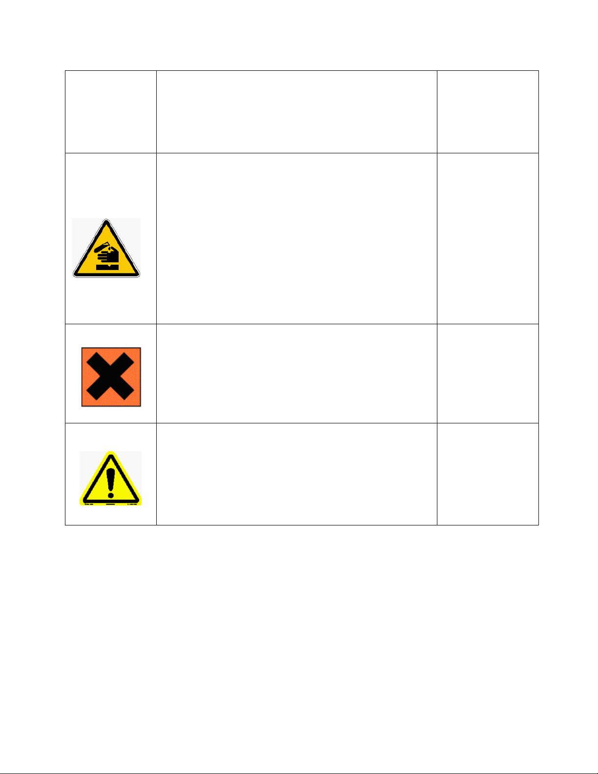
has professional experience to avoid electrical hazards and dangers.
Hazard of chemical burns
Warning of general hazard
To avoid potentially fatal electrical shock and/or analyzer damage
always disconnect input power to analyzer before servicing.
This symbol is used to represent a hazard of severe burns or injury
due to handling of dangerous chemicals. All handling, maintenance
and filling operations of chemicals labeled with this symbol should
be made by qualified personnel in accordance with national or local
regulations. Qualified Personnel means a person who has been fully
trained and has the professional experience to avoid chemical
hazards and dangers. Before handling the chemicals or proceeding
with service operations, read the material safety data sheets
supplied with each chemical and follow all necessary precautions
when handling.
Harmful
Involved parts:
· Fluids section
· reagent containers
Involved parts:
Specific warning depending on the parameter analyzed and the
chemical colorimetric method used. See appendix of the manual.
This symbol means that is necessary read the manual before
proceeding to any service operation in order to properly perform
the operation. Only qualified personnel, fully trained on the
analyzers use and maintenance are allowed to proceed with service
operations on the unit.
1.1.3 Reagents
The Model CA-6 Analyzer is based on colorimetric analysis methods, using chemical solutions. For the
dangers and hazards regarding the chemicals used for the analysis, refer to the Chapter 5 Reagents
Preparation.
Make sure that proper safety precautions are taken (e.g. using safety gloves and glasses) during handling
the chemical solutions and the reagents containers / bottles.
Read carefully the Material Safety Data Sheets of each chemical.
All bottles of the reagents must be labeled with the specific hazards and dangers labels.
· Fluids section
· Reagent containers
4

1.1.4 Sample Stream
Take appropriate precautions to avoid direct contact with sample stream. It is the responsibility of the
user to collect all the information and take all the precautions regarding physical, chemical, radiation
and/or biological hazards and dangers coming from sample stream and/or sample vapors. It is also
responsibility of the user to collect all the information and potential hazards regarding the chemical and
physical compatibility of sample stream with the analyzer materials.
Table 1-2: List of materials used in the Model CA-6 Analyzer
Pump tubing Silicon or Norprene®
Fittings PP
Connection tubing Norprene® / Si lic o n
Colorimetric cell Quartz Glass
Micro perista ltic Pump Norprene® / PP
Mixing membrane pump PP / EPDM
Pinch valve Norprene® / Silico n tubing
1.1.5 Waste disposal of the liquid reagents for the colorimetric reaction
The liquid from the drain of the colorimetric cell may need to be collected in a separate canister. For
guidelines on disposal consult the requirements of the Local Authority for chemical waste regulation.
Arrange removal by a Disposal Company.
1.1.6 Analyzer General Hazards
1.1.6.1 Electrical precautions and hazards
Power to the CA-6 Analyzer must be routed through an ON/OFF power switch.
Mind the electrical shock and/or electrocution labels placed on the analyzer.
All electrical devices powered by 110/220 VAC present the hazard of electrical shock or electrocution.
The analyzer enclosure is equipped with a door that requires a special key for opening to protect all the
personnel involved in analyzer use and maintenance.
Only Qualified Service Personnel should have access to the key that opens the analyzer.
Before servicing the analyzer or any parts that are electrically powered, turn off the power to avoid the
risk of electrocution.
Inside the analyzer’s lower level, the electrical protection is IP2X. Analyzer’s enclosure is IP54.
Protection against electrical shock is guaranteed by the grounding of all isolated metal surfaces.
Grounding terminal/screw is located inside the electrical enclosure, in Upper Left position.
It is the user’s responsibility to periodically check the efficacy of analyzer’s electrical ground.
In case of loss of power, the analyzer stops and automatically restarts as soon as power is returned.
5

1.1.6.2 Operating precautions and hazards
HAZARD: Mechanical hazards caused by moving parts such as the peristaltic pump, the motor...
PREVENTIVE ACTIONS:
To avoid risks the analyzer’s moving parts have been designed, built and located in an enclosure with a
special key. When present inside the enclosure, these parts have protection covers to avoid any contact
and physical injuries to users.
HAZARD: Hazard of burns and poisoning caused by contact with dangerous chemicals
PREVENTIVE ACTIONS:
To avoid risks, the analyzer’s parts that can cause contact with chemicals have been designed, built and
located in closed enclosure with a special opening key. Before servicing the liquids section, read the
material safety data sheets supplied with each chemical to take all the necessary precautions when
handling. Wear eye protections, gloves, mask and protective clothing if necessary.
HAZARD: Hazard of poisoning caused by waste gas leaking from the hydraulic parts or waste collector.
PREVENTIVE ACTIONS:
Install the analyzer in location of adequate dimensions and in a well ventilated area.
HAZARD: Hazard of electric shock and/or electrocution inside the electrical enclosure.
PREVENTIVE ACTIONS:
The analyzer’s electric equipment complies with EN 60204 requirements.
To avoid risks, the analyzer’s parts that can cause hazard of electric shock and/or electrocution have
been designed, built and located in an enclosure with a special key. When working inside the enclosure,
these parts have protective covers and warning labels to avoid any contact and serious injuries or death
to users.
Note:
Electrical equipment, input power and grounding must comply with all national and local regulations
and laws.
Check that the source voltage to be used corresponds with that requested by the analyzer.
Check periodically the power cord as well as the analyzer grounding.
1.1.6.3 Chemical and waste gas hazards
The analyzer has been designed, built and equipped to avoid risks caused by physical and chemical
factors such as noise, vibrations, radiations, dust, waste gas etc.
6
2.0 INTRODUCTION – Analyzer Description
This manual provides general information regarding the principles of
operation, the proper installation and operation of the CA-6 Analyzer.
The Model CA-6 is an on-line sequential sampling analyzer (a sequence of
sampling, analysis and result processing), using colorimetric methods.
The analyzer is assembled with two separated sections with two lockable
doors. The bottom section is the LIQUIDS section. It includes all of the
components involved in the flow, mixing and reaction stages of the sample
and reagents (sampling pump, colorimetric reaction cell, reagents micro
pumps,..). Numerous analysis configurations can be programmed,
depending on accessories and of the number of micro pumps mounted in
the Liquid Section. The top section is the ELECTRICAL enclosure. It includes
the main power supply, the controller PCB assembly and the touch screen
interface.
2.1 Applications
The measurement is a colorimetric analysis using an LED light source and a heated colorimetric cell
designed for measuring trace amounts of analyte in water.
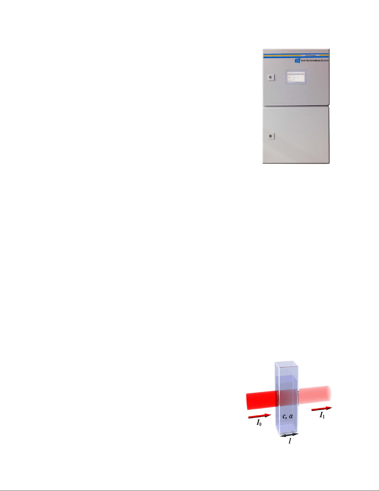
2.2 Working principle: Lambert-Beer law
A colorimetric determination is based on the color formation of a solution after the addition of reagents.
The Absorbance of the solution is measured at a specific wavelength and is related to sample
concentration according to 'Beer's law'.
Lambert–Beer law is an empirical relationship relating the absorption of light to the properties of the
material through which the light is travelling.
The law states there is a logarithmic dependence between the transmission (transmissivity), T, of light
through a substance and the product of the absorption coefficient of the substance, α, and the distance
the light travels through the material (i.e. the path length), ℓ.
The transmission (or transmissivity) is expressed: T = I
Absorbance for liquids is defined as the negative logarithm of the transmittance:
A= - log
T =log101/T =log10I0/I
10
I0: light intensity through the sample before colorimetric reaction
I
: light intensity through the sample after colorimetric reaction
1
In most cases the absorbance has a linear correlation to sample
concentration so a calibration line just requires a zero and span value.
(Zero analyte concentration and the maximum expected
1
/ I
1
0
concentration) are needed. Multiple analysis of the standard are
averaged to gain a reliable calibration line. (See section 8.7)
7
Typical absorbance values range from 0 to 1, but it can be greater than 1.
When the absorbance is 0 then none of the light passing through the sample is absorbed. The intensities
of the sample and reference beam are both the same, so the ratio Io/I
is 1. Log10 of 1 is zero.
1
An absorbance of 1 happens when 90% of the light at that wavelength has been absorbed - which
means that the intensity is 10% of the blank sample reading.
In that case, Io/ I
is 100/10 =10 and log10 (10) = 1.
1
2.2.1 Absorption photometry (Colorimetry):
The methods used are based on the formation of a colored complex of the analyte with a color reagent.
Light with a specific wavelength is transmitted through the reaction mixture. The absorbance of light by
the formed complex is measured by a photometer and related to the concentration of the analyte.
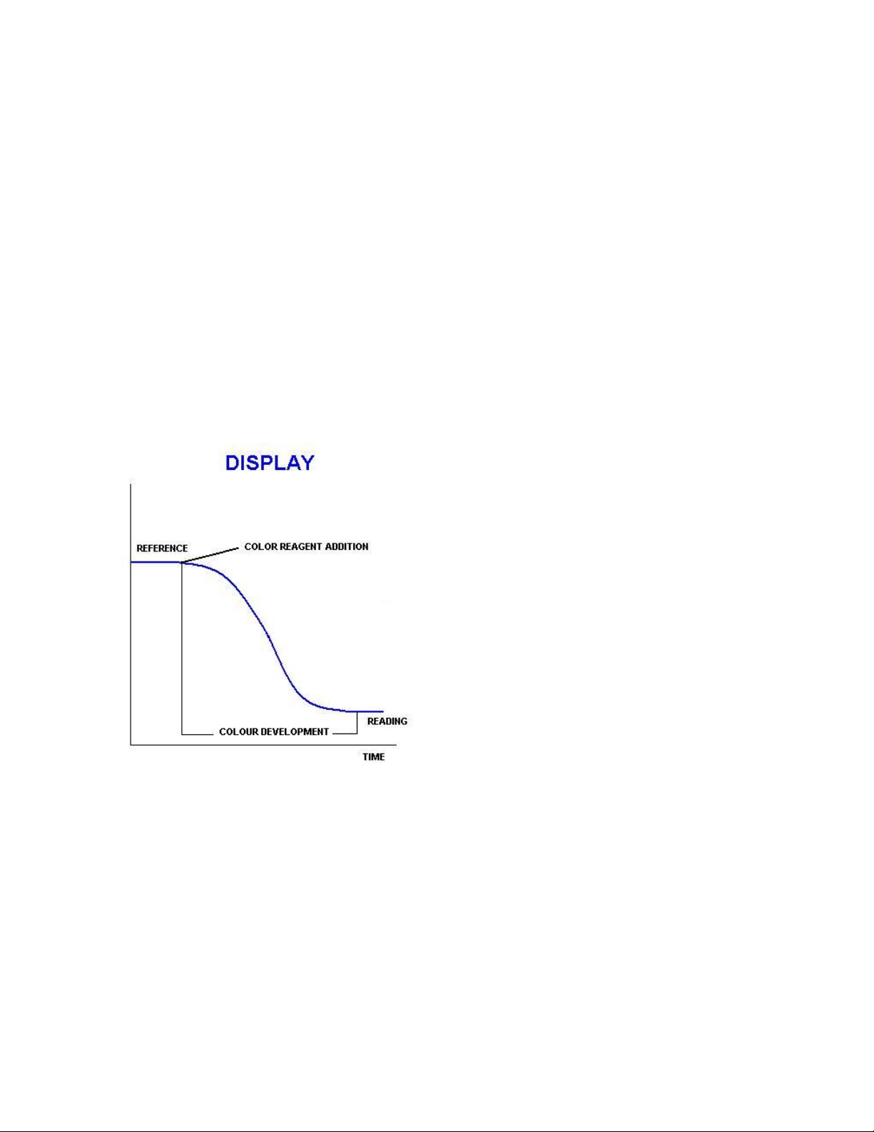
Fig. 2-2: Color development
Absorbance = log (reference / sensor readin g)
The DISPLAY screen of the CA6 displays the live Sensor reading, the recorded Reference reading, the
recorded sensor Reading, the Absorbance and the Blank (the absorbance through deionized water).
8
Conditioning, rinsing and sampling
First the cuvette is drained and rinsed (these steps can also be
and the
Addition of reagent(s)
Depending on the method one or more reagents are added before
Mixing and wait
The mixing pump is activated and the liquid is pumped from the
lower part to the upper part of the colorimetric cell. The waiting
2.3 Analysis Cycle
A typical Analysis Program in the Model CA-6 would have the following structure: Rinse the colorimetric
reaction cell and take a sample, add one or more reagents like a buffer or masking agent and then make
the first measurement, the reference measurement. The reference measurement eliminates interfering
factors such as sample color and turbidity, miscellaneous color from the reagents and refractive index
variations.
After the reference reading, the color producing reagents are added. The sample is mixed and allowed
time to complete the color forming reactions before taking the second measurement, the Reading
measurement. The reference and reading values are used to calculate the concentration using the
calibration factor. The reaction cell is drained and rinsed several times before starting the next
measurement.
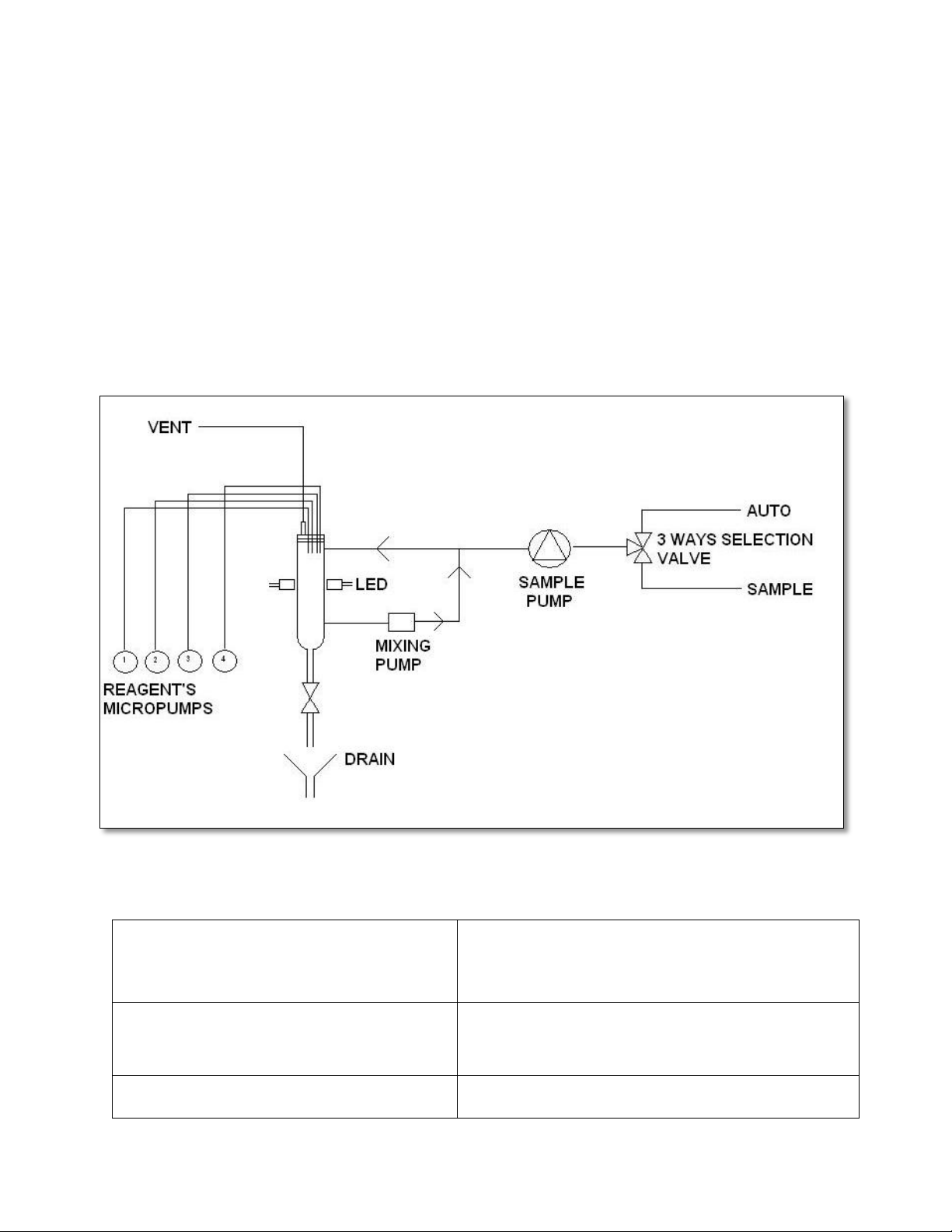
Fig. 2-3 Flow diagram
2.3.1 Typical Run Sequence:
Drain, rinse and sample functions
Add reag function
programmed at the end of the run). The hydraulic lines
colorimetric cell are rinsed prior to taking the actual sample. Then
the sample is taken.
the reference reading.
9

time is programmed in order to eliminate bubbles and allow
First measurement
Measures the light intensity for the base reference value, in order to
start from a fixed reference point and eliminate interfering factors
Addition of color reagent(s)
Depending on the method one or more reagents may be added for
Mixing and wait
The mixing pump is activated and liquid is pumped from the lower
Reading, absorbance and concentration calculation
Reading of the light intensity after the colorimetric reaction,
Drain, conditioning, rinsing, sampling
Drain and rinse of the hydraulic lines and the colorimetric cell.
Waiting time (analysis frequency)
The wait function allows the frequency of the analysis to set.
Mix and wait functions
Reference function
Add reag function
Mix and wait functions
Absorbance and Calculation
Drain, rinse and sample functions
Wait function
suspensions to settle ...
(sample turbidity, color...).
the color development.
part to the upper part of the colorimetric cell; mixing the sample and
the reagent(s). The waiting time is programmed to provide adequate
time to complete the colorimetric reaction.
calculation of the absorbance and of the concentration.
2.3.2 Settings
Analysis cycle – Extra cycle (second level password, administration)
These menus list the sequence of programmable operations run by the analyzer. See actual program
sequences in Section 11 at the rear of the manual.
Both the Analysis Cycle and the Extra Cycle menus have 30 programmable steps. Each step has an
operation and a time associated with it. The time of the operation is in seconds and the maximum
programmable value is 900 seconds. See the list of operations on the following pages. The operations of
absorbance, calculation, calibration, validation, blank and print require only few seconds, 1-2 seconds
each.
The modular design and easily programmed operations make it possible to automate most any
colorimetric laboratory method with up to 4 reagents.
10
2.3.3 Programmable Functions
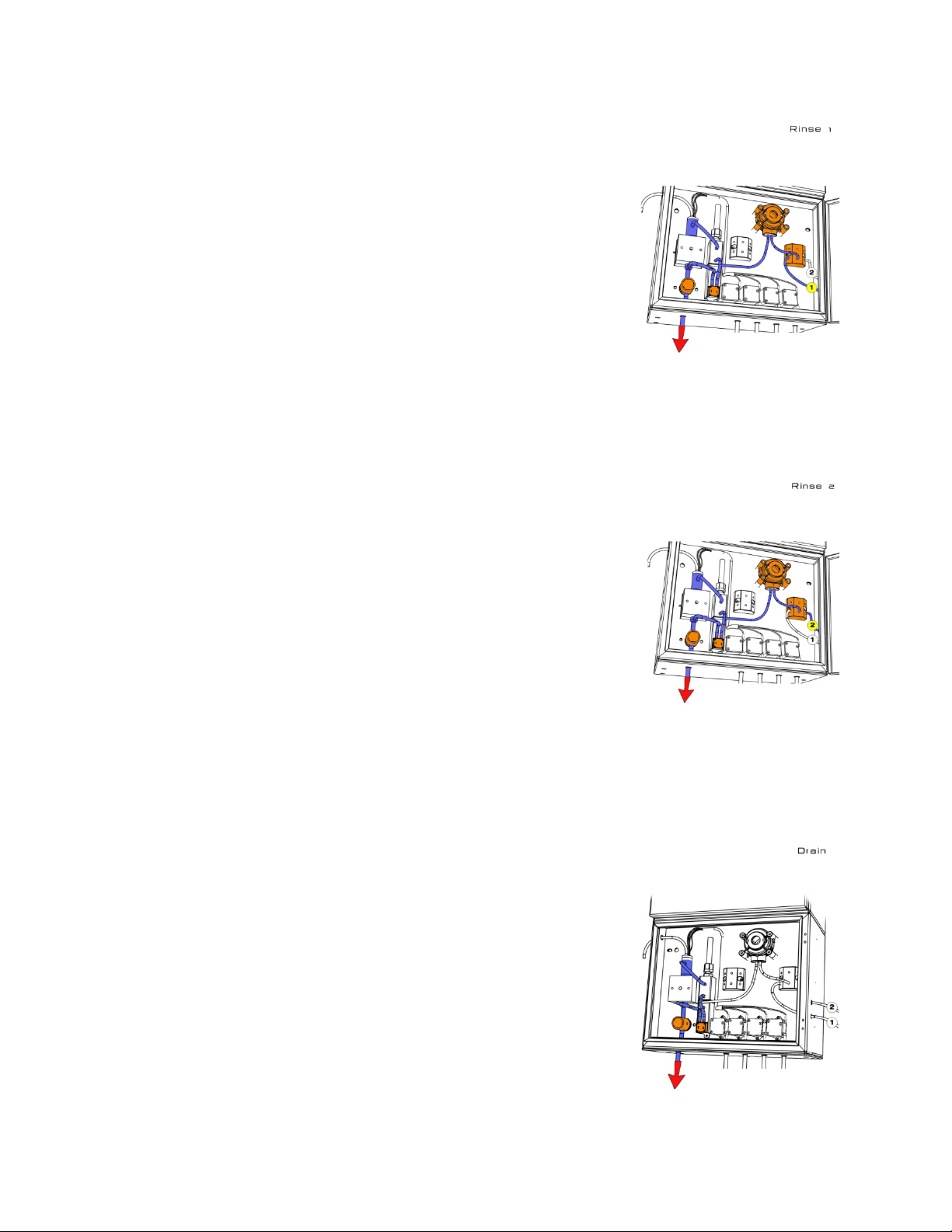
Rinse #1
Rinse #1 opens the bottom pinch valve and Sample #1 flows directly to the
drain. The rinsing time is set in seconds.
RINSE #1 = left side of the selection valve
Rinse #2
Rinse #2 opens the bottom pinch valve and Sample #2 flows directly to the
drain. The rinsing time is set in seconds.
RINSE #2 = right side of the selection valve
Drain
Drain opens the bottom pinch valve, drains colorimetric cell and mixer. The
drain time is set in seconds.
11
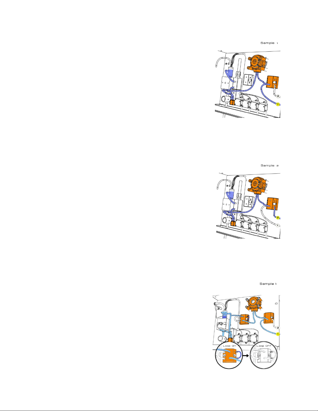
Sample #1
Sample #1 actuates the peristaltic pump with the bottom pinch valve closed
and the colorimetric cell fills with sample #1. The sample time is set in
seconds.
SAMPLE #1 = left side of the selection valve
Sample #2
Sample #2 actuates the peristaltic pump with the bottom pinch valve closed
and the colorimetric cell fills with sample #2. The sample time is set in
seconds.
SAMPLE #2 = right side of the selection valve
Dilution options
Loop On
Loop On allows the sample liquid (sample line #1) that is to be diluted to
flow through the Sample Loop. The Loop On time is set in seconds.
Loop off
Loop Off traps the sample inside the loop tubing while the sample fluid is
flushed from the lines with the dilution water. The Loop off time is set in
seconds.
Loop On
Loop On for the dilution fluid, DI water (sample line #2), dilutes the sample
in the loop tube and fills the Colorimetric Cell.
12
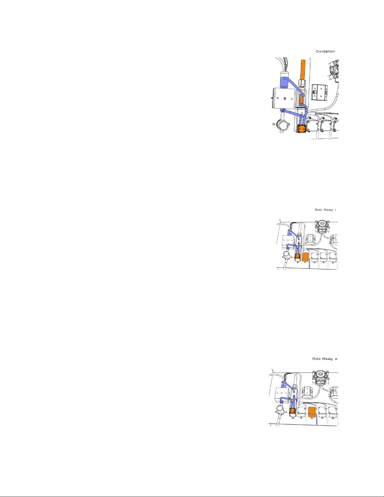
Aux on
Aux On activates an optional auxiliary operation (a digestion, oxidation or
auto-function for a dilution configuration). The picture shows the oxidation
option (On switches the UV lamp on).
Aux off
Aux Off stops the optional auxiliary operation.
Add rea #1
Add rea #1 turns on the micro peristaltic pump for the addition of reagent #1. The
mixing pump is circulating the sample as the reagent is being added. The Add Rea
#1 time is set in seconds.
Add rea #2
Add rea #2 turns on the micro peristaltic pump for the addition of reagent #2.
The mixing pump is circulating the sample as the reagent is being added. The
Add Rea #2 time is set in seconds.
13
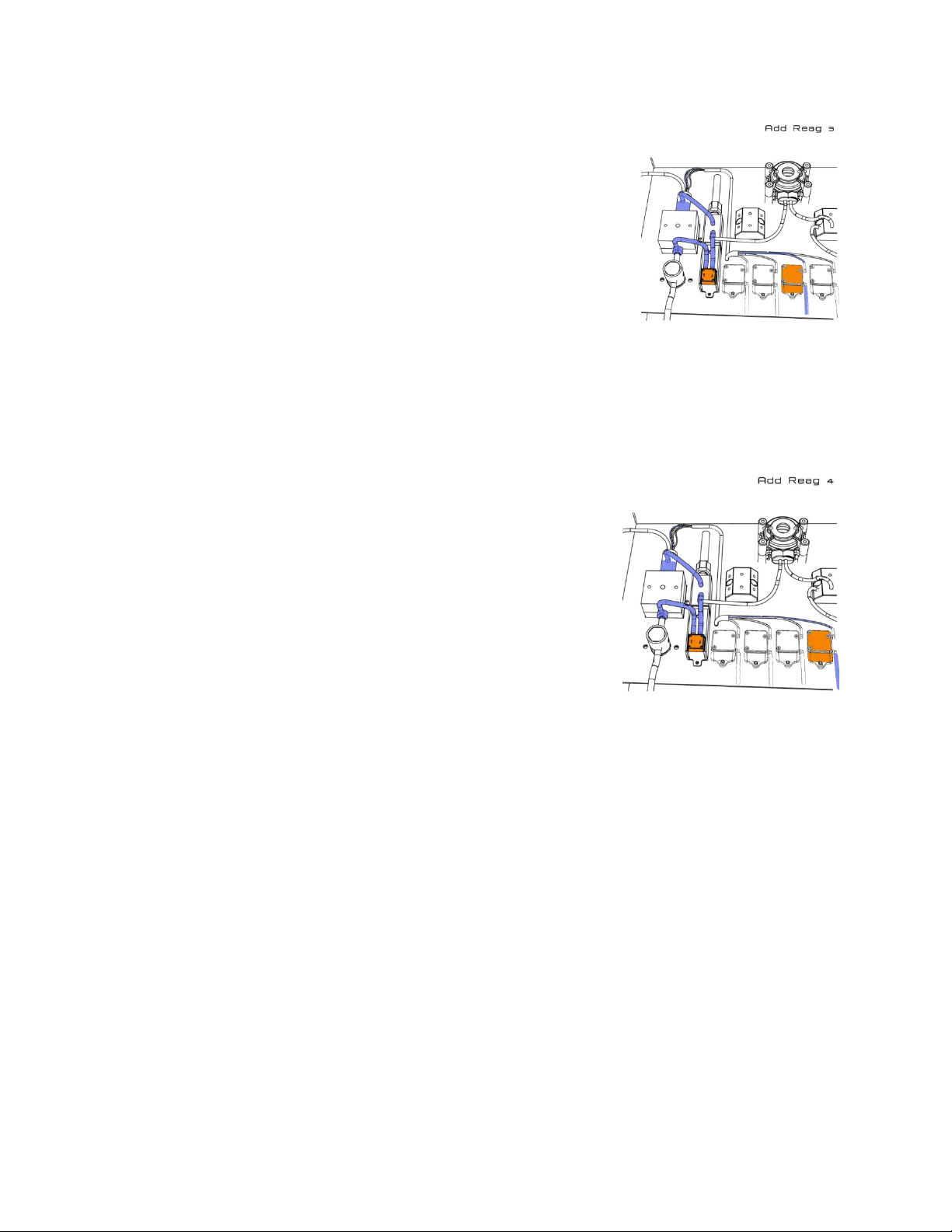
Add rea #3
Add rea #3 turns on the micro peristaltic pump for the addition of reagent
#3. The mixing pump is circulating the sample as the reagent is being
added. The Add Rea #3 time is set in seconds.
Add rea #4
Add rea #4 turns on the micro peristaltic pump for the addition of
reagent #4. The mixing pump is circulating the sample as the reagent is
being added. The Add Rea #4 time is set in seconds
.
Wait
The waiting time is set in seconds. Wait puts the CA6 in Stand By mode.
Mix
The mixing time is set in seconds.
Reference
The reference measurement is the first point for the calculation of the absorbance, I
. Reference sets the
0
time, in seconds, of when to take the base intensity measurement.
Absorbance
Absorbance sets the time, in seconds, of when to take the colored intensity measurement, the Reading,
I
, and calculate the absorbance, I0/ I1. Typically 1 – 2 seconds
1
Calculation
Calculation sets the time in seconds to convert the absorbance reading into a concentration reading and
sends the calculated value to the main display. Calculation uses the absorbance reading and the
calibration factor. Typically 1 – 2 seconds
14
Loading...