

Page 1
ELECTRO-CHEMICAL DEVICES, INC.
SMS-22 Instruction Manual
Sulfide Monitoring System
ELECTRO-CHEMICAL DEVICES, INC.
1681 Kettering, Irvine, CA 92614, USA
Tel: +1-949-336-6060, FAX: +1-949-336-6064
www.ecdi.com
The information and technical data disclosed in this document may be used and disseminated only for the purposes and to the extent specifically
authorized in writing by Electro-Chemical Devices. Electro-Chemical Devices reserves the right to change published specifications and designs
without prior notice. Part No. 33SMS-22 Revision A
PREFACE
Rev: A - 08/13
Page 2

Purchasing products from Electro-Chemical Devices, Inc. provides you with the finest liquid analytical instrumentation
available. If this is your first purchase from ECD, please read this manual before installing and commissioning your new
equipment.
If there are any questions concerning this equipment, please contact your local ECD representative, or the factory
directly at:
Electro-Chemical Devices, Inc.
1681 Kettering
Irvine, CA 92614 USA
Telephone: +1-949-336-6060
FAX: +1-949-336-6064
Website: www.ecdi.com
Email: sales@ecdi.com
© 2013 Electro-Chemical Devices, Inc. All rights reserved. No part of this manual may be used or reproduced in any form or by any means, or stored in a database or
retrieval system without prior written permission from Electro-Chemical Devices, Inc. Making copies of any part of this manual for any purpose other than personal
use is a violation of United States copyright laws. Document printed in the United States of America.
TABLE OF CONTENTS
SMS-22 Page ii
Page 3

PREFACE ................................................................................................................................................................................... i
TABLE OF CONTENTS ............................................................................................................................................................... ii
TERMS AND CONDITIONS OF SALE ........................................................................................................................................ vi
RETURN GOODS POLICY ....................................................................................................................................................... viii
IMPORTANT SERVICE INFORMATION .................................................................................................................................. viii
UNPACKING THE INSTRUMENT .............................................................................................................................................. ix
List of Hazards .................................................................................................................................................................... ix
1.0 GENERAL DESCRIPTION ..................................................................................................................................................... 1
1.1 Features ........................................................................................................................................................................ 2
1.2 Specifications ................................................................................................................................................................ 2
2.0 INSTALLATION ................................................................................................................................................................... 4
2.1 MOUNTING ................................................................................................................................................................... 4
2.2 WIRING .......................................................................................................................................................................... 5
2.2.1 Wiring, Sensor(s) .................................................................................................................................................... 5
2.2.2 Wiring, power ........................................................................................................................................................ 5
2.2.3 Wiring, 4-20 mA Outputs ....................................................................................................................................... 5
2.2.4 Wiring, Contact Relay Outputs ............................................................................................................................... 5
2.3 PLUMBING ..................................................................................................................................................................... 6
2.3.1 Sample Requirements ............................................................................................................................................ 6
2.3.2 Connecting the Inlet and Drain fittings .................................................................................................................. 6
2.3.3 Connecting the Reagents ....................................................................................................................................... 6
2.4 INSTALLING the SENSORS ............................................................................................................................................. 7
3.0 OPERATION ....................................................................................................................................................................... 8
3.0.1 RUN Function ......................................................................................................................................................... 8
3.0.2 PRIME Function ...................................................................................................................................................... 8
3.0.3 CALIBRATE Function ............................................................................................................................................... 8
3.1 KEYS ............................................................................................................................................................................... 9
3.2 MENUS .......................................................................................................................................................................... 9
3.2.1 Sulfide Menus ........................................................................................................................................................ 9
3.2.2 pH Menus ............................................................................................................................................................... 9
3.2.3 Configuration and Trim Menu .............................................................................................................................. 10
3.3 MENU FUNCTIONS & OPTIONS ................................................................................................................................... 10
SMS-22 Page iii
Page 4

3.3.1 Home Screen ........................................................................................................................................................ 10
3.3.2 Graphical Display Screen ...................................................................................................................................... 11
3.3.3 Buffer Menu ......................................................................................................................................................... 11
3.3.4 Set-Up Menu ........................................................................................................................................................ 12
3.3.5 Cycle Settings ....................................................................................................................................................... 13
3.4 OUTPUTS (4-20 mA Channels) .................................................................................................................................... 14
3.4.1 Manual Mode (4-20 mA Hold Function) .............................................................................................................. 14
3.5 ALARM RELAYS ............................................................................................................................................................ 14
4.0 START UP ......................................................................................................................................................................... 15
4.1 POWER UP the ANALYZER ........................................................................................................................................... 15
4.2 CALIBRATION ............................................................................................................................................................... 15
4.2.1 TEMPERATURE SENSORS ..................................................................................................................................... 15
4.2.2 pH SENSOR ........................................................................................................................................................... 16
4.2.3 SULFIDE SENSOR .................................................................................................................................................. 17
5.0 MAINTENANCE ................................................................................................................................................................ 19
5.1 pH and Sulfide electrodes ........................................................................................................................................... 19
5.1.1 Electrode Cartridge Installation ........................................................................................................................... 19
5.1.2 Electrode Cartridge Replacement ........................................................................................................................ 19
5.1.3 Electrode Cleaning ............................................................................................................................................... 19
5.2 Peristaltic Pumps ......................................................................................................................................................... 21
5.2.1 Preparation for Pump/Tubing Service ................................................................................................................. 21
5.2.2 Reagent Pumps .................................................................................................................................................... 22
5.2.3 Sample Pump ....................................................................................................................................................... 22
5.2.4 Tubing and Drain .................................................................................................................................................. 22
6.0 ORDERING INFORMATION .............................................................................................................................................. 24
6.1 ACCESSORIES and SPARE PARTS ................................................................................................................................. 24
7.0 TROUBLESHOOTING ........................................................................................................................................................ 25
8.0 ENGINEERING DOCUMENTATION ................................................................................................................................... 26
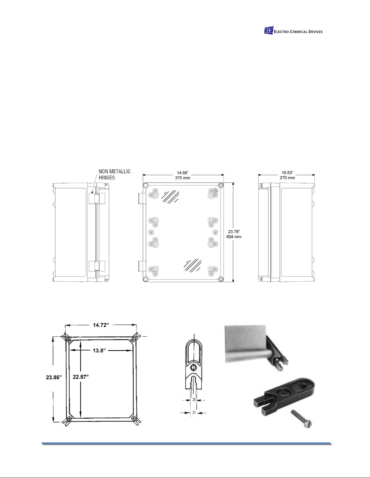
8.1 OUTLINE & DIMENSIONAL DRAWING ......................................................................................................................... 26
8.2 WIRING DIAGRAMS ..................................................................................................................................................... 27
Appendix A ............................................................................................................................................................................ 28
C22 Configuration Screens ................................................................................................................................................ 28
Appendix B ............................................................................................................................................................................ 29
SMS-22 Page iv
Page 5

Reagent Recipes ................................................................................................................................................................ 29
Reagent #1 (16% Potassium Hydroxide) ....................................................................................................................... 29
Reagent #2 (7.5% Hydrochloric Acid) ............................................................................................................................ 30
Appendix C ............................................................................................................................................................................ 30
Scaling Lascar 4-20 mA loop powered indicator ............................................................................................................... 30
SMS-22 Page v
Page 6

TERMS AND CONDITIONS OF SALE
1. ACCEPTANCE. If this writing differs in any way from the terms and conditions of Buyer's order or if this writing is construed as an acceptance or
as a confirmation acting as an acceptance, then Seller’s acceptance is EXPRESSLY MADE CONDITIONAL ON BUYER’S ASSENT TO ANY TERMS AND
CONDITIONS CONTAINED HEREIN THAT ARE DIFFERENT FROM OR ADDITIONAL TO THOSE CONTAINED IN BUYER'S WRITING. Further, this writing
shall be deemed notice of objection to such terms and conditions of Buyer. If this writing is construed as the offer, acceptance hereof is EXPRESSLY
LIMITED TO THE TERMS AND CONDITIONS CONTAINED HEREIN. In any event, Buyer's acceptance of the goods shall manifest Buyer's assent to
Seller's terms and conditions. No addition to or modification of these terms will be effective, unless set forth in writing and agreed to by Seller.
2. WARRANTIES AND REMEDIES
a. Warranty. Seller warrants to Buyer that it holds and will pass marketable title to the goods sold hereunder. Seller warrants to Buyer that the
items and components manufactured by Seller will be free from defects in material and workmanship (subject, however, to tolerances and
variances permitted by the trade hereunder) for a period one (1) year for non-consumable products. Consumable electrodes and sensors have a
conditional warranty based shelf life and process conditions and is determined by Seller.
b. Exclusion and Conditions. Seller’s obligations with respect to the express warranties and remedies contained herein are conditioned on the
following: (i) Buyer's return of the non-conforming goods, if authorized by Seller: (ii) Buyer shall not assign its rights under these express warranties
and any attempted assignment shall render such warranties, but not any disclaimers or limitations, void and the goods sold shall be sold AS IS; and
(iii) all products shall be carefully inspected for damage by Buyer upon receipt, be properly calibrated for Buyer's particular use, and be used,
repaired, and maintained by Buyer in accordance with the instructions set forth in Seller’s product literature. Repair and maintenance by nonqualified personnel, product subjected to misuse or negligence, and/or damaged during shipment will invalidate the warranty, as will the use of
non-approved consumables or spare parts. As with any other sophisticated product, it is essential, and a condition of Seller’s warranty, that all
personnel using the product be fully acquainted with its use, capabilities and limitations as set forth in the applicable product literature.
3. DISCLAIMER OF IMPLIED WARRANTIES. Seller gives no warranties except those expressly contained herein. Seller disclaims all other warranties
implied by law usage of the trade, course of dealing or course of performance including, but not limited to, the Implied warranties of
MERCHANTABILITY and fitness for a particular purpose.
4. LIMITATIONS OF LIABILITY. The following limitations of Seller's liability are acknowledged by the parties to be fair and reasonable and shall apply
to any act or omission hereunder, and to any breach of this contract of which these terms and conditions form a part:
a. Disclaimer of Damage. In no event shall Seller be liable for special, indirect, consequential or incidental damages whether arising under
contract, warranty, tort, strict liability or any other theory of liability. Such damages include but are not limited to loss of profits, loss of use of
goods, damage to property, and claims of third parties.
b. Suitability. Buyer acknowledges that it alone has determined the intended purpose and suitability of the goods sold hereunder. It is expressly
agreed by the parties that any technical or other advice given by the Seller with respect to the use of the goods or services is given without charge
and at Buyer's risk; therefore Seller assumes no obligation or liability for the advice given or results obtained.
c. Notice and Time of Claims.
i. Buyer agrees to check and inspect all products against shipping papers and for damage or shortage upon receipt of goods at destination.
ii. Every claim for shortage, damage in transit, or other cause visible upon inspection shall be deemed waived by the Buyer, or the Buyer’s customer
in the case of resale, unless delivered in writing to Seller by Buyer thirty (30) days from the tender of delivery of the goods to Buyer, provided,
however, that claims for shortage must be made within seven (7) days of receipt.
iii. The parties expressly waive the statute of limitations and agree that any legal proceeding for any breach of this contract shall be waived unless
filed within one (1) year after the accrual of the cause of action thereof.
5. FORCE MAJEURE. Seller shall not be liable for any delay in delivery, or failure to deliver, due to any cause beyond the Seller’s control including
but not limited to fires, floods, or other forces of the elements; strikes, or other labor disputes; accidents to machinery; acts of sabotage; riots;
precedence or priorities granted at the request or for the benefit, directly or indirectly of the federal or any state government or any subdivision or
agency thereof; delay in transportation or lack of transportation facilities; restrictions imposed by federal, state or other governmental legislation
or rules or regulations thereof. If Seller, in its sole discretion, determines that Seller’s performance hereunder would result in a loss to Seller’s on
SMS-22 Page vi
Page 7

this sale as computed under Seller’s normal accounting procedures because of causes beyond Seller's control, then the Seller may terminate this
agreement in whole or in part without liability for any delay in the delivery of, or failure to deliver, the goods sold hereunder
6. TAXES AND OTHER CHARGES. The Buyer will pay, or reimburse Seller if it pays, any and all taxes or tariffs or any other similar charges imposed
upon this contract, the goods covered hereby or the delivery or use or resale thereof.
7. FREIGHT CHARGES. If the sale hereunder is other than F.O.B. Seller's facility, this acknowledgement is based upon the freight charges now in
effect. In the event of an increase or decrease in applicable freight charges before the goods are shipped, such charge in freight will be for the
Buyer's account.
8. PRICES AND DELIVERY. Prices quoted herein are F.O.B. shipping point. Deliveries specified are only our best estimate and are subject to change.
This quotation is based upon freight charges now in effect. Buyer will be invoiced at the freight charge prevailing at the date of shipment. Prices are
firm for orders meeting Seller's normal shipping schedules. If shipments are held or postponed for any reason other than Seller's fault, and a price
increase becomes effective during the period of such hold or postponement, the increase will apply to all shipments that are held or postponed
thirty (30) days or more from the effective date of the increase.
9. PAYMENTS. If in the judgment of Seller the financial condition of Buyer at any time prior to shipment does not justify the terms of payment
specified, Seller may cancel the order, withhold shipment, and/or require full or partial payment in advance. If payment is not made when due,
Seller may suspend all future delivery or other performance with respect to Buyer without liability or penalty and, in addition to all other sums
payable hereunder, Buyer shall pay to Seller (i) the reasonable costs and expenses incurred by Seller in connection with all actions taken to enforce
collection or to preserve and protect Seller’s rights hereunder, whether by legal proceedings or otherwise, including without limitation reasonable
attorneys’ fees, court costs and other expenses and (ii) interest on all amounts unpaid after 30 days charged at the monthly rate of 1-1/2% or the
highest rate permitted by law, whichever is lower.
10. CANCELLATION OR ALTERATION. Buyer may not alter or cancel any order without Seller’s written consent. For any order altered or cancelled
with Seller's consent, Buyer must pay for all expenses and labor incurred up to the time of Seller’s consent, plus a reasonable percentage for profit.
Any order delayed or deferred by Buyer will be subject to price escalation for increased costs of production, and any other expenses caused by the
delay. Material on such orders will be stored at Buyer's risk. Seller reserves the right to invoice Buyer and require payment before shipment of any
delayed or deferred order.
11. TITLE AND RISK OF LOSS. Title and risk of loss shall pass to buyer at Irvine, California, unless otherwise specified in the contract. If delivery is
made by common carrier, risk of loss shall pass upon delivery to the carrier. Claims for loss or damage in transit must be made by Buyer to the
carrier. Seller accepts no responsibility for loss or damage to product in transit.
12. PATENT OR TRADEMARK INFRINGEMENT. If the goods sold hereunder are to be prepared for manufacture according to Buyers specification,
Buyer shall indemnify Seller against any claim or liability for patent, trademark, service mark or trade name infringement on account of
preparation, manufacture and/or sale.
13. NON-WAIVER. If Government Contract Regulations require the addition, deletion, or modification of these terms and conditions upon prior
notification to Seller and Seller's written acceptance thereof, such changes shall become a part of these terms and conditions. Seller shall not be
bound by any Government Contract Regulations applicable to Buyer’s contracts with the U.S. Government unless Buyer has expressly
acknowledged, on the face of this document, the applicability of such Regulations to the transaction between Buyer and Seller contemplated
herein. Absent such acknowledgement, Seller is making the assumption in issuing this document that no such Regulations apply.
14. JURISDICTION. All such disputes shall be resolved in a court of competent jurisdiction in Orange County, California. Buyer hereby consents to
the jurisdiction of the State and Federal Courts sitting in Orange County. Not withstanding the above, should either party contest the jurisdiction of
such courts, the other party may institute its suit in any court of competent jurisdiction.
15. APPLICABLE LAW. All questions arising hereunder or in connection with the quotations or any order submitted in connection therewith and/or
the performance of the parties hereunder shall be interpreted and resolved in accordance with the laws of the state of California without regard to
its conflict of law provisions and excluding the United Nations Convention on the International Sale of Goods.
SMS-22 Page vii
Page 8

RETURN GOODS POLICY
All requests for returned goods must be initiated through our Customer Service Department. Please call our phone number (949)
336-6060 with the specifics of your request. The following conditions must be satisfied for consideration of applicable credit for the
return of products purchased from Electro-Chemical Devices:
1) The item is unused and in the original package.
2) The item was shipped directly from Electro-Chemical Devices.
3) The item has not been damaged in shipment to Electro-Chemical Devices.
4) Items containing date-sensitive parts such as electrodes, must be returned within 1 month of the invoiced date.
5) Items without date-sensitive parts must be returned within 3 months of the invoiced date.
A Return Merchandize Authorization Number must be obtained from Customer Service and be provided on all paperwork and
packaging. To obtain a Return Merchandize Authorization Number, please provide the reason for return, the date of purchase, your
original purchase order number, and either our order number or our invoice number. The issuance of a Return Merchandize
Authorization Number is a verbal approval for return only and does not guarantee credit or allowance. Returned goods must be
received within 30 days of the issuance date of the Return Merchandize Authorization Number or it will become null and void.
Necessary physical and mechanical inspection is completed upon receipt of the item. Applicable credit or equivalent allowance is
determined after inspection of the returned item. If all of the above conditions are met, and the item has been approved to return
to our stock, a restocking charge of 25% of the purchase price is deducted from the applicable credit.
IMPORTANT SERVICE INFORMATION
Use only factory authorized components for repair. Tampering or unauthorized substitution of components may adversely affect the
operation of this product and may void the warranty.
If service or repair is required, please obtain the serial number(s) or sales order number of the product(s) in question and contact
ECD’s Service Department at:
+1-800-729-1333 (USA/Canada) or +1-949-336-6060
or email Service@ecdi.com
A Return Material Authorization (RMA) number must be obtained from the service department before returning any material to
ECD. All material returned to ECD shall be shipped prepaid to the factory.
SMS-22 Page viii
Page 9
Hazard of electrical shock
Involved parts:
Hazard of chemical burns
Involved parts:
Harmful
Involved parts:
Warning of general hazard
UNPACKING THE INSTRUMENT
Your Electro-Chemical Devices instrument has been carefully packaged to protect it from damage during shipment and
dry storage. Upon receipt please follow the procedure outlined below.
1. Before unpacking, inspect the condition of the shipping container to verify proper handling by the carrier. If
damage is noted, save the shipping container as proof of mishandling for the carrier.
2. Check the contents of the shipping container with the items and quantities shown on the packing list.
Immediately report any discrepancies to ECD.
3. Save the original packing material until you are satisfied with the contents. In the event the product(s) must be
returned to ECD, the packing material will allow you to properly ship it to ECD.
4. Familiarize yourself with the instrument before installation, and follow proper installation and wiring
procedures.
List of Hazards
This symbol is used to present a hazard of severe electric shock or
electrocution. All controls and maintenance on electrical devices
labelled with this symbol should be made by qualified personnel in
accordance with national or local regulations. Qualified Personnel
means person who has been fully trained and has professional
experience to avoid electricity hazards and dangers. To avoid
potential fatal electrical shock and/or ana ly z er damage always
disconnect input power to analyzer before servicing.
·main power supply
·peristaltic pump
motor
·input terminal
This symbol is used to present an hazard of severe burns and seroius injury
for dangerous chemicals manipulation. All handling and manipulations
operations maintenance on chemical s l abell ed with thi symbol s hould be
made by qualified personnel in accordance with national or local regulations.
Qualified Personnel means person who has been fully trained and has
professional experience to avoid chemical hazards and dangers. Before to
proceed to every handling of chemicals and to proceed with service
operations, read the material safety data sheets supplied with each chemical
to take all the necessary precautions when handling.
Specific indication depending on the parameter analysed and the chemical
colorimetric method used. See appendix of the manual.
This symbol means that is necessary read this manual before to proceed to
any service operation to know exactly how to operate in proper way. Only
qualified personnel or bbbbully trained on analyzer use and maintenance is
allowed to proceed with service operations on the unit.
· fluidics section
· reagent container
· fluidics section
· reagent container
SMS-22 Page ix
Page 10
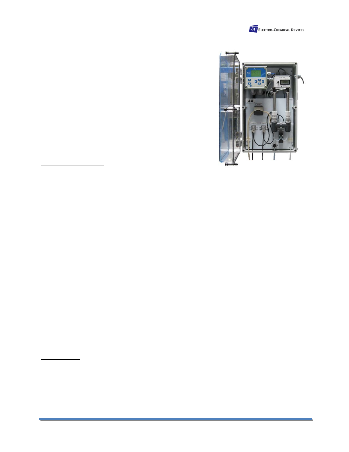
1.0 GENERAL DESCRIPTION
The ECD SMS-22 Sulfide Measurement System is an all in one
analyzer for the continuous measurement of sulfide ions in aqueous
solution. Sulfide ions are present in well water, municipal waste
water and waste waters from refineries, tanneries, chemical plants
and paper and pulp facilities.
Hydrogen sulfide (H
that “rotten egg” odor. H
S) is a gas that dissolves in water and gives it
2
S exists as a dissolved gas in acidic water,
2
as bisulfide ions (HS-) in water with pH values above pH 7 and as
sulfide ions (S
-2
) in water with very high pH values, values above pH
12.
The ECD SMS-22 uses a sulfide ion selective electrode (ISE) to measure the total amount of sulfide
present in the sample. The measurement must be made at high pH levels where S
-2
exists. Potassium
hydroxide (KOH) is added to raise the pH of the sample to around pH 13 and a pH electrode measures
the actual pH. Sulfide and bisulfide exist in a pH dependent equilibrium with the ratio dependent on the
pH. The sulfide ISE measures the sulfide present in the sample and the pH measurement infers what
percentage of the total sulfide was measured. The C22 calculates and displays the Total sulfide present.
The highly caustic sample is then neutralized with HCl and the pH is measured and displayed to verify
the neutralization. The KOH is neutralized with HCl producing potassium chloride salt (KCl) and water.
The neutralized sample can be disposed of as waste or returned to the water supply. Each cycle uses
about 1 ml of caustic and 1 ml of acid.
The analyzer is set to run 6 minute analysis cycles (10 cycles per hour) but can easily be programmed to
run 12 minute cycles (5 cycles per hour) or 30 minute cycles(2 cycles per hour). Running continuously at
10 cycles per hour, the SMS-22 uses 10 liters (2.5 gallons) of each reagent per month and at 2 cycles per
hour less than 2 liters (0.5 gallon) per month.
The 6 minute cycle is composed of 3 x 2 minute cycles.
1. Sample fill 0:00-0:30 minutes: seconds
2. Drain 1:50-1:59 minutes: seconds
3. Sample fill 2:00-2:30 minutes: seconds
4. Drain 3:50-3:59 minutes: seconds
5. Sample fill 4:00-4:30 minutes: seconds
Add KOH 4:00-4:30 minutes: seconds
6. Measure sulfide 4:50-4:59 minutes: seconds
7. Add HCl 5:00-5:30 minutes: seconds
8. Measure pH 5:40-5:49 minutes: seconds
9. Drain 5:50-5:59 minutes: seconds
SMS-22 Page 1
Page 11
1.1 Features
• Continuously measures the Total Sulfide present in
aqueous solutions up to 500 ppm
• Plumb and Play Design, Ready to Use, factory Calibrated
• Grey, molded fiberglass IP66 enclosure with Clear
polycarbonate cover, easy installation, NEMA 4X
• S10 Sulfide and S10 pH electrodes
• Reliable and Easily serviced Peristaltic pumps for
reagents and sample
• C22 Analyzer Capability, Dual Measurements, multiple
outputs, timers, relays, logic gates, 110/220 VAC Power
1.2 Specifications
Sensor and Flow Train
Sensors:
Sulfide Ion Electrode, Ag
pH Electrode, General purpose pH glass with double junction reference cell
Measurement Range:
Sulfide: 0.02 to 500 ppm
pH: 0 to 14 pH
Reagent Use:
Less than 2 gallons each per month of 16% KOH and 7.5% HCl at 10 cycles per hour
Operating Temperature:
0° C to 50° C (32° F to 122° F)
Sample Flow rate:
Sample from ambient pressure
Minimum flow, 1.5 L/hour
Wetted Materials:
PVC, PP, PTFE, Glass, 316 SS, silicone, Norprene tubing
Process Connections:
Input ⅜” Tubing, Drain ⅜” Tubing
Cycle Time:
User Defined, 6 minutes (default), 12 minutes or 30 minutes
Analyzer Settings
Run, Calibrate, Prime
C22 Analyzer:
Measurements:
Sulfide: 0.02 to 500 ppm
pH: 0 to 14 pH
Temperature: 0° C to 100° C (32° F to 212° F)
S solid state pellet with double junction reference cell
2
SMS-22 Page 2
Page 12

pH Compensation:
pH 11 - 14 (accuracy degrades rapidly below 11 pH)
Display:
2.5” X 1.75” backlit LCD, 4 lines for Text & Graphical
Enclosure:
NEMA 4X, LxWxD: 5.7” x 5.7” x 7
Outputs:
(1) 4-20 mA for Sulfide set to Sensors Range, user configurable
(1) 4-20 mA for pH set 0-14 pH, user configurable
Alarm Relay Ratings:
(4) SPDT 230 VAC/5A or 30 VDC / 5A resistive max.
Input Power
110/220 VAC @ 50/60 Hz
24 VDC (12 to 50 VDC) @ 1.5 A
Display
Lascar 4-20 mA loop Powered indicator
Model: DPM 742-BL
SMS-22 Page 3
Page 13
2.0 INSTALLATION
Mount the SMS-22 in a location where there is easy access to the analyzer and sensors. Install the
system in an area where vibrations, electromagnetic and radio frequency interference are minimized or
absent.
Do not mount in direct sunlight or areas of extreme heat. The SMS-22 is suitable for outdoor use if
mounted with a protective cover or sunshield.
Provide access to drain or atmospheric sample return. Sample Conditioning Cell overflow and spent
sample must drain to atmospheric pressure, no back pressure.
Reagents should be stored below the SMS – 22 or within 3 feet (1 meter) to either side.
2.1 MOUNTING
The SMS-22 can be direct mounted through the four corner holes of the enclosure or by using the four
fiber glass reinforced polyamide brackets which are mounted directly to the rear of the box.
SMS-22 Page 4
Page 14

2.2 WIRING
All adjustments and maintenance on electrical devices should be made by qualified
personnel in accordance with national or local regulations.
No Service should be carried out on the instrument without first switching off the power.
Electrical wiring should only be conducted by qualified personnel. See the wiring color code for the SMS22 in Section 8.2 below.
2.2.1 Wiring, Sensor(s)
The MVS10 Sulfide Sensor and the PHS10 pH Sensor were connected to the C-22 analyzer at the factory,
no additional connections are necessary. Color coded connections for these sensors are shown in the
wiring diagrams in Section 8.2 or on the inside cover of the C22 analyzer.
2.2.2 Wiring, power
Attach power cable as shown in the diagram in Section 8.2. Feed the cable through the gland fitting on
the right hand side of the SMS-22. Tighten the cable gland to provide a good seal to the cable.
2.2.3 Wiring, 4-20 mA Outputs
Connections to the DCS or PLC should be made with 22 gauge, twisted pair communication cable. The
standard configuration has Total Sulfide on mA 1 and pH on mA 2. The 4-20 mA outputs are powered
outputs. Attach the output cables as shown in the diagram in Section 8.2. Feed the cables through the
gland fitting on the right hand side of the SMS-22. Tighten the cable gland to provide a good seal to the
cables.
2.2.4 Wiring, Contact Relay Outputs
The standard configuration has four SPDT 230V 5 A relays that are wired to the drain solenoid and the
various reagent and sample pumps. There are no alarm relays available on the SMS-22.
SMS-22 Page 5
Page 15

2.3 PLUMBING
2.3.1 Sample Requirements
Minimum flow: 0.4 gal/hour, (1.5 L/hr)
Temperature: 32° to 122°F (0° to 50°C)
Sample Pressure: Drawn from atmospheric pressure
The Sample Conditioning Cell provides an atmospheric sample point that can adapt to changing sample
flows between 0.4 and 10 gal/hr (1.5 -37 L/hr).
2.3.2 Connecting the Inlet and Drain fittings Sample Inlet:
The sample must be drawn from atmospheric pressure. The sample feed tube is 8 mm OD x 4.8 mm
bore (5/16” OD x 3/16” bore). The sample tube can be placed directly in an open reservoir of the sample
water or connected to the reservoir with a 3/16” barb fitting.
A Sample Conditioning Cell is available for pressurized samples. This Fast Flow Reservoir allows the
sample to fill a 200 ml sampling cell and overflow the balance of the feed to an atmospheric drain. The
input to the sample cell is a ¼” barb fitting is supplied for sample
connection but a compression style tube fitting can also be used (not
supplied). The sampling port is a stainless steel tube that
accommodates the sample feed tubing to the analyzer. The overflow
drains through the 12 mm overflow tubing exiting the bottom of the
Sample Conditioning Cell. Attach a length of 12 mm soft tubing and
allow the overflow to drain to open atmosphere. Do not restrict the
drain line. The pressurized feed must have an adjustable shut off
valve. Adjust the feed so that the Sample Conditioning Cell fills and
starts overflowing in 2 minutes or less. Filling the cell in 2 minutes
provides the minimum sample flow (1.5 liters/hour), faster feed rates
simply overflow to the drain.
Sample Drain:
The neutralized sample and the water from the rinse cycles drain
from the measurement cell when the solenoid valve is actuated. The
drain line must drain to atmospheric pressure.
2.3.3 Connecting the Reagents
DANGER: Read any precautions and the (MSDS) datasheets, wear protective gloves,
clothes and glasses before handling chemical products.
Hazard of severe burns or injury due to handling of dangerous chemicals
Connect the tubing from the reagent pumps to the insertion tubes. Press the insertion tube from
Reagent Pump 1 through the grommet in the cap of the 16% KOH solution. Press the insertion tube from
Reagent Pump 2 through the grommet in the cap of the 7.5% HCl solution.
SMS-22 Page 6
Page 16

2.4 INSTALLING the SENSORS
The SMS-22 is supplied with the sensor cables pre-wired to the analyzer. Simply install the sensors in the
flow cell as described below.
The Sulfide and pH sensors mount in the Flow Cell using the supplied ¾” compression gland fittings.
Remove the protective cap(s) from the sensors and save them for future use. The cap contains a
potassium chloride solution, use care when removing the cap from the sensor to avoid spillage. Loosen
the compression fitting on the flow cell to allow the sensor to be inserted into the fitting. Insert the
sensor into the fitting using a twisting motion. There is a swage type seal and an o-ring seal inside the
fitting, the twisting motion will facilitate passing these seals. Gently slide the sensor to the bottom of the
flow cell and hand tighten the compression nut to fix the sensor’s position. Repeat the same installation
process for the other sensor.
The SMS-22 instrument and sensors were calibrated at the factory and should be ready for use when
assembled. However, changes may have occurred during shipping and storage that require recalibration.
(See Calibration section below)
SMS-22 Page 7
Page 17

3.0 OPERATION
This section will provide a basic overview of the RUN, PRIME and CALIBRATE functions of the SMS-22
Analyzer. The Menu structure and the functions of the MENU SELECT keys and the CALIBRATE keys.
3.0.1 RUN Function
The ECD SMS-22 is a sequential sampling analyzer. RUN sequences through the following analysis cycle;
1. Fill the measurement cell with sample and drain (Rinse Cycle)
2. Fill and drain (Rinse Cycle)
3. Add caustic and Fill (Sample)
4. Mix the solution and measure the Sulfide ion
5. Adjust the Sulfide 4-20mA output signal
6. Add acid, mix, measure the pH
7. Adjust the pH 4-20mA output signal,
8. Drain the flow cell and repeat the cycle.
MVS10 Sulfide Ion Electrode only measures the sulfide
-2
ion (S
sample. It does not “see” bisulfide (HS
sulfide (H
convert most of the H
The S
) component of the total sulfide present in the
-
) or hydrogen
S). The pH of the sample must be raised to
2
S and bisulfide into sulfide ion.
2
-2
proportion of the total sulfide varies from 0%
at pH 9 to 100% at pH 15, see Figure 3.1. The PHS10
pH sensor provides the pH value needed to calculate
the total amount of sulfides present in the water.
After the caustic, 16% KOH, has been added and the
sulfide measurement made, the sample is neutralized
100
% Sulfide vs pH
80
60
40
% S-2
20
0
10 12 14
pH
with 6.5% HCl to bring the pH back into the neutral
range. The reaction, HCl + KOH → KCl + H
O, hydrochloric acid plus potassium hydroxide forms
2
potassium chloride and water which can be sent to the drain or added back to the sample water.
3.0.2 PRIME Function
The PRIME function powers Reagent pumps #1 and #2 and the Sample pump until it is switched off. This
allows the pumps to be easily primed after refilling the reagent bottles or changing the peristaltic
tubing. The Drain is Open and the 4-20 outputs are locked while the PRIME switch is ON.
3.0.3 CALIBRATE Function
The CALIBRATE function cuts the power to all of the pumps and drain valve. The 4-20 outputs are locked
while the CALIBRATE switch is ON. This allows the sensors to be removed from the flow cell and
calibrated in standard solutions.
SMS-22 Page 8
Page 18

Screen Displayed
Button Pressed
Home Screen
MENU SELECT ▼
Graphical display
MENU SELECT ▼
Parameter Selection Screen (Ch 1 Buffer)
MENU SELECT ▼
Parameter Selection Screen (Ch 1 Set-Up)
MENU SELECT ▼
Parameter Selection Screen (Ch 1 Status)
MENU SELECT ▼
Configure/ Trim Menu
MENU SELECT ▲..... To return to the Home screen
3.1 KEYS
The blinking cursor indicates
the active point where menus
can be selected or numerical
values adjusted. There are two
sets of keys on the C22
analyzer, the MENU SELECT
keys and the CALIBRATE keys.
The MENU SELECT keys are
used to move the cursor
vertically changing the
displayed menu. These keys
are also used to Save/Accept the calibration data and exit the calibration menu.
The CALIBRATE keys are used to enter menus, change numerical values and move the cursor.
To ENTER a menu or parameter adjustment line simultaneously press both of the Horizontal
CALIBRATE keys, ◄CALIBRATE►
Pressing either of the Horizontal CALIBRATE keys separately will move the cursor horizontally to the
point under the digit to be adjusted. The Vertical CALIBRATE keys are used to adjust numeric values.
Pressing the upper key will increase the value and pressing the lower key will decrease the value. When
the cursor is on a menu line, not in a menu setting a parameter, pressing the down CALIBRATE key will
return the cursor to the HOME Screen from any menu.
3.2 MENUS
There are two sets of menus on the Model C-22. The Channel 1 menus (PV1) are the Sulfide Ion menus,
the Channel 2 menus (PV2) are the pH menus. Pressing the MENU SELECT UP key will access the pH
channel, pressing the MENU SELECT DOWN key will access the Sulfide Ion channel. See the guide below
for the general menu structure.
3.2.1 Sulfide Menus
3.2.2 pH Menus
SMS-22 Page 9
Page 19

Screen Displayed
Button Pressed
Home Screen
MENU SELECT ▲
Parameter Selection Screen (Ch 2 Status)
MENU SELECT ▲
Parameter Selection Screen (Ch 2 Set-Up)
MENU SELECT ▲
Parameter Selection Screen (Ch 2 Buffer)
MENU SELECT ▲
Contrast (adjustment screen)
MENU SELECT ▼….. To return to the Home screen
Screen Displayed
Button Pressed
Configure/Trim
◄ CALIBRATE ► (enter screen)
Passwords
MENU SELECT ▼(allows menus to be password protected)
Default Display
MENU SELECT ▼(defines Home Screen)
4-20 assign
MENU SELECT ▼(Assigns parameter/function to mA output)
Manual Mode
MENU SELECT ▼(Allows manual control of mA outputs)
Relay assign/Test
MENU SELECT ▼(Assigns triggering parameter to a relay)
PID Assign
MENU SELECT ▼(Assigns PID to a PV)
PWM Assign
MENU SELECT ▼(Assigns Pulse Width Modulation to a PV)
Clock and timers
MENU SELECT ▼(Sets Clock function, assigns Timers)
Logic Gates
MENU SELECT ▼(assigns AND/OR gates)
Ion Species
MENU SELECT ▼(Sets Ion Measured)
General
MENU SELECT ▼( Not Used)
°C/°F & Temp Cal
MENU SELECT ▼( allows temperature trim/cal, choose °C/°F)
4-20 Trim/Test
MENU SELECT ▼(allows mA trim)
Millivolt Trim
CALIBRATE ▼ (return to Home Screen)
3.2.3 Configuration and Trim Menu
The Configure/Trim menu provides access to the menus used to assign parameters, define functions and
trim input and output signals. This group of menus should rarely be needed as the instrument was
configured at the factory before testing and shipment. The basic structure is as follows. See the “System
22 Configuration Manual” for details about these menus, available at www.ecdi.com
.
3.3 MENU FUNCTIONS & OPTIONS
This section describes the functions of each of the Menu items and how they are configured and used.
3.3.1 Home Screen
The Home Screen displays the Channel 1 PV, Sulfide ppm, % mA output and temperature. Channel 2 PV
displays the pH Value, % mA Output and temperature. When the cursor is on a menu line, not in the
menu setting a parameter, pressing the down (▼) CALIBRATE key will return the cursor to this screen,
the HOME Screen, from any menu.
SMS-22 Page 10
Page 20

Screen Displayed
Button Pressed
Ch1 Buffer
Ch1 Status
◄ CALIBRATE ► (enter the calibration menu by pressing
1 S-- 1.00 ppm
Cal -710 mV
Press ◄ CALIBRATE ► to start the Cal,
Place sensor in Cal Solution (5 ppm)
1 S-- 1.00 ppm
Cal -730 mV
Set the Sulfide value using the CALIBRATE ◄ or ► to move
cursor. Use the ▲or▼ to adjust the integer value.
1 S-- 5.00 ppm
Cal -730 mV
MENU SELECT ▼ (accept Calibration)
1 S-- 5.00 ppm
Cal -730 mV
MENU SELECT ▼ (move to Cal)
1 S-- 5.00 ppm
Cal -730 mV
MENU SELECT ▼(move to Cal 2, Slope)
2 S-- 5.00 ppm
Cal 29.1 mV/dec
◄ CALIBRATE ► (enter Cal Line)
Place sensor in 2nd Cal Solution (50 ppm)
2 S-- 0.00 ppm
Cal 30.0 mV/dec
Set the Sulfide value using the CALIBRATE ◄ or ► to move
cursor. Use the ▲or▼ to adjust the integer value.
3.3.2 Graphical Display Screen
This Graphical Display is only available in the Channel 1 menu. It is located one screen down from the
Home Screen. It displays a user assigned output value, for example, 4-20 mA1 vs. time. The Graphical
display variables of which Output to display and what Time interval are used is configured in the Channel
1 Set-Up Menu. See Section 3.3.4, below, for more information on the Set-Up Menu.
3.3.3 Buffer Menu
The Buffer Menus are Calibration Menus. To access the Buffer Menu the cursor must be flashing in front
of the “_Ch 1 Buffer” line. To enter the Calibration screen, simultaneously press both of the Horizontal
CALIBRATE keys. The calibrations are structured for either a single point or two point calibrations.
The first calibration “1 S-- 1.00 ppm” is the “zero point” calibration. The zero point calibration sets a
base millivolt value to a sulfide ion concentration. This is the base point or zero point for a two point
calibration. The Cal 1S-- 1.00 ppm line is also used to Standardize the sulfide reading to a laboratory
determined value. With the Sulfide and pH sensors in a solution of known value, enter that value in the
“1 S-- xx.xx ppm” line. The Cal value, xxx.x mV, is the mV value from the sensor. It can be reset to the
factory default value by “entering” the Cal line.
The second calibration screen is the “slope, mV/decade” calibration. This calibration should use a
solution with a concentration at least 10 times higher than the first calibration solution. Scroll down to
the “2 S-- X.XX ppm” line and enter the value of the calibration solution. The Cal line will display the
new slope, mV/dec.
Sulfide Calibration
Ch1 Setup
both ◄► simultaneously)
SMS-22 Page 11
Page 21

2 S-- 50.00 ppm
Cal 30.0mV/dec
MENU SELECT ▼ (accept Calibration)
Slope has been set at 30.0 mV/decade
2 S-- 50.00 ppm
Cal 30.0 mV/dec
CALIBRATE ▼ (return to Home Screen)
Screen Displayed
Button Pressed
Ch2 Buffer
Ch2 Status
◄ CALIBRATE ► (enter the calibration menu by pressing
1 pH 7.00 pH
Cal .0 mV
◄ CALIBRATE ►(enter line, zero pt. Cal 1)
Sensor should be in a 7.0 pH solution.
1 pH 7.00 pH
Cal 0.2 mV
MENU SELECT ▼ (accept Calibration when reading is
stable)
1 pH 7.00 pH
Cal 0.2 mV
MENU SELECT ▼ (move to Cal line)
1 pH 7.00 pH
Cal 0.2 mV
MENU SELECT ▼(move to Cal 2, Slope)
Remove and rinse sensor with distilled water
2 pH 10.00 pH
Cal 59.1 mV/pH
◄ CALIBRATE ► (enter Cal Line)
Place Sensor in a pH 10.00 solution
2 pH 10.00 pH
Cal 60.2 mV/pH
Set the pH value using the CALIBRATE ◄ or ► to move
cursor. Use the ▲or▼ to adjust the integer value.
2 pH 10.00 pH
Cal 60.2 mV/pH
MENU SELECT ▼ (accept Calibration)
2 pH 10.00 pH
Cal 60.2 mV/pH
CALIBRATE ▼ (return to Home Screen)
Screen Displayed
Button Pressed
Ch1 Buffer
Ch1 Status
◄ CALIBRATE ► (enter Set Up Menu)
Plot 4-20 1 Graphical Display
Sample .1 m
MENU SELECT ▼
(the “4-20 1” indicates the displayed value, variable)
Plot 4-20 1
Sample .1 m
MENU SELECT ▼
(the Sample time is 0.1 minutes, variable)
4mA1 .0 ppm OUTPUT SET-UP
20mA1 999.9 ppm
◄ CALIBRATE ► (enter 4mA line)
pH Calibration
Ch2 Setup
both ◄► simultaneously)
3.3.4 Set-Up Menu
The Setup menu allows the various parameters to be configured for the user’s requirements. Each
Channel has a Set-Up Menu that includes the parameters associated with that specific Channel. The
Graphical Display, 4-20 mA Outputs Timers and Alarm Relays are all configured in the Setup Menu.
Set Up Channel 1 Menu
Ch1 Setup
SMS-22 Page 12
Page 22

4mA1 .1 ppb
20mA1 999.9 ppt
To adjust the value use the CALIBRATE ◄ or ► to move
cursor. Use the ▲or▼ to adjust the integer value.
4mA1 .1 ppb
20mA1 999.9 ppt
MENU SELECT ▼ (accept the Value)
4mA1 0.1 ppb
20mA1 999.9 ppt
MENU SELECT ▼
4mA1 0.1 ppb
20mA1 999.9 ppt
◄ CALIBRATE ► (enter 20mA line)
4mA1 0.1 ppb
20mA1 999.9 ppt
To adjust the value use the CALIBRATE ◄ or ► to move
cursor. Use the ▲or▼ to adjust the integer value.
4mA1 0.1 ppb
20mA1 10.0 ppm
MENU SELECT ▼ (accept the Value)
4mA1 0.1 ppb
20mA1 10.0 ppm
MENU SELECT ▼
(4-20 mA1 is set to 0.1 ppb to 10 ppm)
Screen Display
Settings
10 cycles per hour
5 cycles per hour
2 cycles per hour
Timer 1 : periodic
Per 0d00 :06 :00
Off 0 00 :04 :30
Per 0d00 :12 :00
Off 0 00 :08 :30
Per 0d00 :30 :00
Off 0 00 :20 :30
Timer 2 : periodic
Per 0d00 :02 :00
Off 0 00 :00 :30
Per 0d00 :04 :00
Off 0 00 :00 :30
Per 0d00 :10 :00
Off 0 00 :00 :30
Timer 3 : periodic
Per 0d00 :06 :00
Off 0 00 :05 :30
Per 0d00 :12 :00
Off 0 00 :11 :00
Per 0d00 :30 :00
Off 0 00 :22 :30
Timer 4 : periodic
Per 0d00 :02 :00
Off 0 00 :01 :59
Per 0d00 :04 :00
Off 0 00 :03 :59
Per 0d00 :10 :00
Off 0 00 :09 :59
Timer 5 : periodic
Per 0d00 :06 :00
Off 0 00 :00 :10
Per 0d00 :12 :00
Off 0 00 :00 :10
Per 0d00 :30 :00
Off 0 00 :00 :10
Timer 6 : one shot ↑
Now 0 00 :00 :00
Off 0 00 :00 :59
Now 0 00 :00 :00
Off 0 00 :09 :40
Now 0 00 :00 :00
Off 0 00 :21 :40
Timer 7 : one shot ↑
Now 0 00 :00 :00
Off 0 00 :01 :49
Now 0 00 :00 :00
Off 0 00 :11 :49
Now 0 00 :00 :00
Off 0 00 :24 :10
3.3.5 Cycle Settings
Default settings are for 10 cycles per hour
(KOH Relay #1)
(Sample Relay #2)
(HCl Relay #3)
(Drain Relay #4)
(MM)
(Sulfide MM)
Now 0 00 :00 :00
On 0 00 :04 :00
Now 0 00 :00 :00
On 0 00 :00 :00
Now 0 00 :00 :00
On 0 00 :05 :00
Now 0 00 :00 :00
On 0 00 :01 :50
Now 0 00 :00 :00
On 0 00 :00 :00
On 0 00 :00 :50
Now 0 00 :00 :00
On 0 00 :08 :00
Now 0 00 :00 :00
On 0 00 :00 :00
Now 0 00 :00 :00
On 0 00 :10 :30
Now 0 00 :00 :00
On 0 00 :03 :50
Now 0 00 :00 :00
On 0 00 :00 :00
On 0 00 :09 :30
Now 0 00 :00 :00
On 0 00 :20 :00
Now 0 00 :00 :00
On 0 00 :00 :00
Now 0 00 :00 :00
On 0 00 :22 :00
Now 0 00 :00 :00
On 0 00 :09 :50
Now 0 00 :00 :00
On 0 00 :00 :00
On 0 00 :21 :30
(pH MM)
On 0 00 :01 :40
SMS-22 Page 13
On 0 00 :11 :40
On 0 00 :24 :00
Page 23

TC .333 %/°C
Dissoc 0.001 On
Temperature Compensation, no adjustment needed
MUST BE ON, value varies with the pH according to the pKa
Noise filter 5
Settings
Settings
4mA 0.00 pH
20mA 14.00 pH
Contrast 5
Isopot XXX.X mV
Equilib 11.98 pH
Set Up Channel 2 Menu
Isopotential point, MANDITORY ENTRY
Equilibrium value for Sulfide ion dissociation, pKa
3.4 OUTPUTS (4-20 mA Channels)
The SMS-22 has two 4-20 mA outputs. The Sulfide channel, mA1 is configured for 0-10 ppm Sulfide Ion,
although all values are configurable. (See Section 3.3.4 above) The second 4-20 mA output is configured
for 0-14 pH. The SMS-22 uses a Lascar DPM-742-BL Loop Powered indicator to convert the 4-20 mA1
output into ppm sulfide reading. This unit must be re-scaled whenever the 4-20 mA range is changed.
(See Appendix C)
3.4.1 Manual Mode (4-20 mA Hold Function)
The % Output values are displayed on the Home Screen for the S-output, mA 1, and for the optional pH Output, mA 2. Manual
Mode is an output Hold function commonly used to freeze the
outputs during maintenance and calibration cycles. While in
Manual Mode the Output can be adjusted between 0 and 99.9%
using the CALIBRATE keys. This is very useful for troubleshooting
loop communication problems.
In the SMS-22 the outputs are configured to be under manual
mode control at all times except when the reading is taken. An “M” will be displayed in front of the %
Output value indicating the output is being held at the “Last Value”. The Output will remain frozen at
the last value until the next measurement cycle when the Manual Mode is switched off for 10 seconds
to acquire the next reading.
The mA outputs are only updated in the RUN cycle. The values are frozen when the SMS-22 is in the
CALIBRATE or PRIME cycles.
3.5 ALARM RELAYS
TheSMS-22 uses all four available relays to control the pumps and drain valves used in the SMS-22.
There are NO alarm relays available in the SMS-22.
SMS-22 Page 14
Page 24

4.0 START UP
Complete each of the sections listed below (see Section 2 Installation).
1. Mounting the Analyzer
2. Wire the power and outputs
3. Plumb the sample, reagent and Drain lines
4. Install the sensors in the flowcell
4.1 POWER UP the ANALYZER
Verify:
1. The sample line is connected to the Sample Conditioning Cell or other atmospheric sample port
that has sample water flowing.
2. Reagent 1 (16% KOH) is connected to Reagent Pump 1
3. Reagent 2 (7.5% HCl) is connected to Reagent Pump2
4. The Drain Line empties to an atmospheric drain with no back pressure
The Standard Configuration is Power =ON, Calibrate/Run =RUN, Prime/Run =RUN.
PRIME the PUMPS
1. Switch the Power Switch to ON
2. Switch Prime/Run to PRIME, this powers the Sample pump, reagent pumps and opens the Drain.
The mixing pump is not active. Prime the pumps for 1 minute for each meter (3 ft) of tubing
between the analyzer and Sample point or Reagent (whichever is longest).
3. Switch Prime/Run to RUN
4. Switch the Power Switch to OFF and then back ON (this Resets the C-22 timers to 00.00.00)
The SMS-22 is now running online and it will update the 4-20 mA outputs at the end of each cycle.
Channel 1, 4-20 mA = 0-10 ppm Sulfide and Channel 2, 4-20 mA = 0-14 pH.
The Standard cycle time is configured for 6 minutes, 10 cycles per hour. See Section 3.3.5 above for the
settings for 5 cycles/hour or 2 cycles/hour.
4.2 CALIBRATION
The SMS-22 was calibrated before shipping and should not require calibration at Start Up. If Calibration
is required perform the calibrations in the following sequence, calibrate the Temperature Sensors then
the pHS10 Sensor and finally the Sulfide Ion Sensor.
4.2.1 TEMPERATURE SENSORS
Both the pH sensor and Sulfide Ion sensor have temperature sensors. They should display the same
temperature, the sample temperature.
To calibrate the sensors,
1. Switch the SMS-22 Analyzer to CALIBRATE Mode
2. Remove the sensors from the flow cell and place them in a beaker of solution.
SMS-22 Page 15
Page 25

3. Allow the sensors and a thermometer to equilibrate for at least 10 minutes
4. Verify the displayed temperature agrees with the thermometer
5. If not, then adjust the temperature of the sulfide sensor to agree with the thermometer in the
Configure/Trim Menu → °C/°F & temp cal → 1 Trim °C menu. (see section 3.2.3 above)
6. Repeat in the 2 Trim °C menu, for the pH sensor.
This calibration was performed in the factory calibration but it is advisable to perform a temperature
check every 2-3 months.
4.2.2 pH SENSOR
The PHS10 pH sensor was calibrated with pH 7.0 and pH 10.0 buffers at the factory before shipping.
Periodically verify the displayed pH agrees with the actual pH.
4.2.2.1 Single Point Calibration (Standardization)
If the displayed pH value deviates by more than 0.2pH from the sample pH then the pH sensor should
be recalibrated,
1. Switch the SMS-22 Analyzer to CALIBRATE Mode
2. Remove the PHS10 pH sensor from the flow cell and place it in a beaker of pH7 buffer.
3. Scroll up to the Ch2 Buffer Menu (see Section 3.3.3 above)
4. ENTER the Menu and ENTER the 1 pH 7.00 pH line
5. When the mV reading has stabilized SAVE the reading (MENU SELECT ▼)
6. It is recommended to proceed down to the 2 pH 10.00 pH screen, the slope calibration (Section
4.2.2.2 below)
Alternatively the reading could be STANDARDIZED on line to agree with a laboratory determined pH
value for the sample solution. The SMS-22 must be switched to CALIBRATE mode with sample in the
flow cell or the sensor must be removed from the flow cell and placed in a beaker of the sample.
1. Switch the SMS-22 Analyzer to CALIBRATE Mode with untreated sample in the flow cell
2. Scroll up to the Ch2 Buffer Menu (see Section 3.3.3 above)
3. ENTER the Menu and ENTER the 1 pH 7.00 pH line
4. Adjust the pH value to the value determined by the laboratory measurement
5. When the mV reading has stabilized SAVE the reading (MENU SELECT ▼)
6. Return to HOME screen (CALIBRATE▼)
4.2.2.2 Two Point Calibration
1. Switch the SMS-22 Analyzer to CALIBRATE Mode
2. Remove the PHS10 pH sensor from the flow cell and place it in a beaker of pH 7.00 Calibration
Buffer.
3. Scroll up to the Channel 2 Buffer Menu and ENTER the menu by pressing both horizontal
CALIBRATE keys, ◄ CALIBRATE ► (See section 3.3.3 above)
SMS-22 Page 16
Page 26

4. ENTER the Cal1 line and adjust the calibration value to pH 7.00. When the mV value has
stabilized accept the value by pressing the down MENU key (MENU SELECT ▼). An Acceptable
mV value is < ±60 mV zero point offset.
5. Rinse the sensor and place it in a beaker of pH 4.01 or 10.0 Calibration buffer for the second
point calibration.
6. Scroll down and ENTER the Cal2 Line. Enter the value of the Calibration Solution and accept the
calibration when the mV/pH value has stabilized. An Acceptable value is > 54 mV/pH.
7. Rinse the sensor and return it to the SMS-22 flow cell.
4.2.3 SULFIDE SENSOR
The MVS10 Sulfide Ion Sensor was calibrated in 5 ppm and 50 ppm sulfide solutions at the factory.
Calibrations should always be two point calibrations. The pH sensor must be in the sulfide ion calibration
solution during calibration since the sulfide ion measurement is pH compensated. The Calibration is not
pH compensated and the compensation must be done manually.
The MVS10 sulfide ion sensor has a linear range from 0.3 ppm to 30,000 ppm. Measurements outside of
this range are difficult to impossible with the SMS-22 analyzer. It is possible to set the range of the
instrument to as low as 20 ppb but the accuracy of the measurement is severely degraded above 1 ppm.
Consult with the factory for more information about low level measurements, sales@ecdi.com
.
1. Switch the SMS-22 Analyzer to CALIBRATE Mode
2. Remove the PHS10 pH sensor and MVS10 Sulfide sensor from the flow cell, clean them (see
Section 5.1.3 below) and place them in a beaker of 5.0 ppm Sulfide Solution. Swirl sensors
through the calibration solution for at least 30 seconds. Wait for the sensors to stabilize.
3. Scroll down (MENU SELECT key) to the Channel 1 Set Up menu, Enter the menu by pressing both
horizontal CALIBRATE keys, then scroll down (MENU SELECT key) to the TC Screen. The
dissociation factor on the bottom line of the screen is the pH correction factor. Record the
factor and exit the screen. Calculate the Calibration Value.
Dissociation Factor x ppm value of the Calibration Solution = Calibration Value
Example: 0.958 x 5.00 ppm = 4.79 ppm
4. Scroll down to the Channel 1 Buffer Menu and ENTER the menu by pressing both horizontal
CALIBRATE keys, (See section 3.3.3 above)
5. ENTER the Cal1 line and adjust the calibration value to 1 S-- 4.79 ppm. When the mV value has
stabilized accept the value by pressing the down MENU key. An Acceptable mV value is -720 mV
± 20 mV for a new electrode, the readings will trend more negative as the electrode ages.
6. Rinse the sensors and place them in a beaker of 50.0 ppm Sulfide Solution for the second point
calibration.
7. Exit the Cal 1 screen and scroll down to the TC Screen, Record the dissociation factor for the 50
ppm Calibration Solution and exit the screen. The factor is usually different for different strength
solutions so check the value and do not assume it is the same as the 5 ppm solution. Calculate
the 50 ppm Calibration Value. Example: 0.977 x 50 ppm = 48.85 ppm
8. Scroll down and ENTER the Cal2 Line. Enter 2 S-- 48.85 ppm and accept the calibration when
the mV/dec value has stabilized. An acceptable value is -29 mV/dec ± 3 mV.
SMS-22 Page 17
Page 27

9. Rinse the sensors and return them to the SMS-22 flow cell.
SMS-22 Page 18
Page 28

5.0 MAINTENANCE
5.1 pH and Sulfide electrodes
All electrochemical sensors require periodic cleaning and/or replacement. The life of an electrode is
completely dependent on the process conditions it is exposed to. An electrode may last a year or longer
in potable water and only a few weeks in a hot caustic bath. The chemical constituents in the process
may coat the electrode surfaces requiring the electrode to be removed and cleaned or replaced.
Cleaning agents should be specific to the type of coating the electrode was exposed to, detergents and
alcohols for removing greases and oils, acids for removing hard water scales and metallic deposits or
high pressure spray washing for flocculants and biofilms.
5.1.1 Electrode Cartridge Installation
Unless ordered separately, electrode cartridges are generally shipped installed in a sensor. Sensors
ordered without an electrode are shipped with a shipping plug to keep contamination from getting
inside the sensor during shipment or storage. The following procedure explains how to install the
electrode cartridge in the sensor assembly:
1. Remove the shipping plug by turning it counterclockwise.
2. Remove the electrode cartridge from the protective soaker boot. Be careful not to flex the
electrode body while removing the tape and the protective boot.
3. Rinse the electrode tip in tap water and wipe the electrode body dry then lubricate the o-ring
seals with the included lubricant. Save the protective soaker boot in the event the electrode must
be stored at a future time.
4. Carefully insert the electrode cartridge into the sensor assembly by turning until hand tight. The
first o-ring, closest to the front of the electrode, will be slightly visible if held horizontally.
NOTE: IF EXCESS FORCE IS REQUIRED DURING ELECTRODE INSTALLATION, CHECK FOR PROPER THREAD
ENGAGEMENT OR FOR AN OBSTRUCTION.
5.1.2 Electrode Cartridge Replacement
Periodic replacement of the electrode cartridge is required for pH, ORP and Specific Ion sensors. The
following procedure explains how to replace the electrode cartridge in the sensor assembly:
1. Remove the electrode cartridge from the front of the sensor assembly by turning it
counterclockwise.
2. For installation procedure follow steps 2, 3, and 4 in section 8.3.1 electrode cartridge
installation.
5.1.3 Electrode Cleaning
An important aspect of sensor maintenance is the service of the electrode cartridge. After being in
operation, an electrode may begin to exhibit slow response or non-reproducible measurements. This
may be due to coating of the measurement electrode or clogging of the reference junction. Regular
electrode cleaning reduces problems associated with the coating and clogging. Frequency of cleaning
will depend on the process and application. The following procedures are used to clean pH electrodes.
SMS-22 Page 19
Page 29

If possible, the electrode should be cleaned without removing it from the sensor body. However, if the
electrode must be removed, the o-rings must be inspected and re-lubricated.
Remove the pH sensor from the flow cell and carefully wash the wetted end of the electrode cartridge
in a mild solution of detergent and water or with isopropyl alcohol. If the electrode response is not
improved, soak the electrode in 0.1 Molar HCl for 5 minutes. Remove and rinse the electrode with tap
water and soak in 0.1 Molar NaOH for 5 minutes.
Remove the electrode from the NaOH solution, rinse the electrode and soak in a 4 pH buffer solution for
10 minutes. This should improve the response of the electrode. If not, replace the electrode.
If the electrode must be left out of the process for an extended period of time, store it in a solution of
water saturated with KCl or a 4.0 pH buffer solution. ECD does not recommend the storage of electrodes
in distilled or deionized water.
Ion selective electrodes require periodic service. Weekly checks should be performed to assure the
accuracy of the measurement.
The ion selective crystal that senses the ion concentration can become sluggish in response due to
coating or reactions with the process solution. Periodic cleaning or polishing will minimize drift and
maintain the sensors response.
CLEANING
The solid state crystal based sulfide electrodes are fairly robust and can be cleaned with alcohols,
detergents or dilute acids to remove coatings caused by greases, oils or films. A soft tooth brush or
paper towel should be used to remove stubborn coatings. Do not clean with a wire brush. Metal
carryover from the brush will compromise the measurement. Cleaning should be followed by polishing
before calibrating the sensor.
POLISHING
Abrasive polishing is only recommended for the solid state crystal style Combination Electrodes. ECD
supplies two styles of abrasive cleaning kits, a package of light blue colored polishing strips or a small
vial of alumina powder with a felt polishing pad.
The sensing surface of solid state electrodes can wear over time, which causes drift, poor reproducibility
and loss of response in low level samples. The electrode can be restored by polishing the sensing surface
with a polishing kit. The polishing kit can also be used if the sensing surface has been etched or
chemically poisoned.
a. Place a small amount of the alumina polishing powder near one of the edges of the
polishing pad or use the blue polishing strip.
b. Place a few drops of distilled water on the pad to wet the powder or strip.
c. Hold the electrode with the sensing surface facing down on the wetted polishing
pad/powder.
d. Slide the electrode back and forth across the pad, the sensing tip will be abraded and a
new electrode surface will be generated.
SMS-22 Page 20
Page 30

e. Polish the electrode for about 30 seconds and examine the tip for a shiny metallic
surface, repeat if necessary.
f. Rinse the electrode with distilled water and soak the electrode in a low ppm Calibration
solution.
g. Perform a Two Point Calibration.
Storage
The method for Storage of the sensor is dependent on time.
For short term storage of several days the sensor can be stored inside the flow cell. No special
consideration is needed. Stop the analyzer and manually actuate the drain, this will leave a trace
amount of moisture in the flowcell and keep the sensors from dehydrating for a few days.
For periods greater than 3-4 days the sensors must be removed from the flow cell, cleaned and stored in
the protective shipping cap filled with salted tap water (1 teaspoon table salt in 4 oz of tap water).
5.2 Peristaltic Pumps
The Reagents pumps and Sample pump use high performance tubing designed a one year service life
when measuring clean water samples. Oily/greasy samples will degrade the tubing performance
requiring replacement of the tubing and pump heads in a shorter period of time.
The standard service kit contains two reagent pump heads, and a full set of tubing and fittings required
to rebuild the analyzer.
DANGER: Read any precautions and the (MSDS) datasheets, wear protective gloves,
clothes and glasses before handling chemical products.
Hazard of severe burns or injury due to handling of dangerous chemicals
5.2.1 Preparation for Pump/Tubing Service
The SMS-22 uses two hazardous chemicals during the analysis, 10% Potassium Hydroxide and 10%
Hydrochloric Acid. These solutions must be rinsed from the system before any maintenance to the
reagent pumps or tubing is performed. It is recommended to perform this rinsing procedure before
servicing any of the pumps or tubing.
1. Turn OFF the power to the Analyzer
2. Turn OFF the Sample Feed Line
3. Position an open 1 liter or larger container of distilled water (tap water is OK to use) near the
reagent containers.
4. Disconnect the sample feed tubing from the Sample Conditioning cell and place it in the
container of distilled water.
5. Remove the 16% KOH reagent feed tube from the carboy and place it in the container of
distilled water.
6. Remove the 7.5% HCl reagent feed tube from the carboy and place it in the container of distilled
water.
7. Set the Control switches to RUN and PRIME
SMS-22 Page 21
Page 31

8. Turn the power ON for 2-3 minutes to flush all of the lines with water.
9. Turn the power switch OFF and proceed with scheduled maintenance
5.2.2 Reagent Pumps
The reagent pumps use a replaceable pump head design. There are no serviceable parts on these pump
heads, replaceable tubing or otherwise. The pump heads should be replaced yearly or when
inconsistent results are generated. Follow these steps to replace the pump heads.
1. Perform the Preparation for Pump Service, 5.2.1 above
2. Verify the power to the analyzer OFF
3. Disconnect the reagent feed tube from the pump head. Use care when disconnecting the
reagent tube to avoid spilling liquid inside the analyzer.
4. After disconnecting the feed tube, hold the tube vertically to allow the water to drain back into
the rinse water sample beaker.
5. Disconnect the reagent output line from the pump head and allow it to drain to the flow cell.
6. Remove the two screws from the face of the pump head.
7. Gently pull the pump head directly back off of the motor drive shaft.
8. Dispose of the old pump head
9. Align the keyed shaft to the new pump head and gently press it into place.
10. Re-attach the pump head to the panel with the two mounting screws. (supplied with pump
head)
11. Connect the reagent input and output lines to the pump head.
12. Follow START UP procedure (Section 4.0) when all maintenance is complete.
5.2.3 Sample Pump
The Sample pump uses the replaceable tubing design common to most peristaltic pumps. The tubing
should be replaced yearly or when inconsistent results are generated. Follow these steps to replace the
pump tubing.
1. Perform the Preparation for Pump Service, 5.2.1 above
2. Verify the power to the analyzer OFF
3. Disconnect the feed tube from the Sample Conditioning Cell and the Sensor Flow Cell. Use care
when disconnecting the tubing to avoid spilling liquid inside the analyzer.
4. Lift the Tan colored lid on the Sample feed pump all the way up to release the tubing.
5. Remove the old tubing and properly dispose of it.
6. Connect the New Tubing to the Sample Conditioning Cell and the Sensor Flow Cell.
7. Slide the new tubing into the opened pump and close the lid to secure the tubing in place.
8. Repeat the same procedure for the Mixing Pump.
9. Follow START UP procedure (Section 4.0) when all maintenance is complete.
5.2.4 Tubing and Drain
The Reagents pumps and Sample/Mixing pumps use high performance tubing designed for a one year
service life when measuring clean water samples. All tubing and fittings should be visually inspected for
SMS-22 Page 22
Page 32

signs of leakage or degradation of the material on a monthly basis. The Drain tube should be examined
for leakage when the flow cell is full or slow drainage after the solenoid has actuated, the tubing is
adhering to itself and not releasing the flow. Replace the Drain tubing if either condition exists.
Depending on the chemical make-up of the sample stream this tubing could require replacement every
two to three months.
The solenoid Drain Valve is a knife blade style shut off valve that is constantly pressing against the tubing
to provide a seal. When the solenoid is actuated it releases the pressure on the tube allowing the liquid
in the flow cell to drain. The valve can be released manually by pressing the black circulator portion on
the valve. The valve is supplied with a BLOCK that should be inserted into the gate whenever the
analyzer is not in use. This relieves the pressure on the tubing extending its service life. The tubing may
fuse together and not reopen if left in a compressed position for extended periods of time, weeks to
months.
SMS-22 Page 23
Page 33

Model SMS-22 Complete System
Part #
Model and Description
1210000-1
Complete System in NEMA 4 Enclosure with (2) 2.5 gallon reagent containers
Instruments, Parts and Accessories
Part #
Model and Description
2000027
Tubing Replacement Kit, 5 pieces, (4) Pump Tubes and (1) Drain Tube
9380016
Reagent Peristaltic Pump Head
2000103-1
Switch #1, RUN-CALIBRATE switch, wired and labeled
2000102-1
Switch #2, RUN-PRIME switch, wired and labeled
2000097-1
Drain Pinch Valve, wired and labeled
2000096-1
Sample Peristaltic Pump, wired and labeled
2000106-1
Mixing Pump, wired and labeled
2000095-1
Reagent #1 Peristaltic Pump, wired and labeled
2000095-2
Reagent #2 Peristaltic Pump, wired and labeled
2000245-1
Flow Cell
2000240-1
Display/Junction box
2005145
pH electrode, RADEL body, dbl jct TFE Ref, Flat pH glass, -10°-90°C
2005122
Sulfide electrode, RADEL body, dbl jct TEF Ref, 0.01-32,000 ppm, 0°-80°C
1000270-2
Fast Loop Reservoir sample cell without Level Switch
6.0 ORDERING INFORMATION
6.1 ACCESSORIES and SPARE PARTS
SMS-22 Page 24
Page 34

Symptom
Possible Cause
Remedy
7.0 TROUBLESHOOTING
The SMS-22 was evaluated and calibrated at the factory before shipment. Upon initial start up the
system should require minimal to no adjustments.
Verify the system has adequate flow, the pH electrode and the temperature sensors are reading
correctly. These parameters effect the measurement and must meet the standards listed in the
Calibration Section above. If these conditions are met and problems still exist use the Troubleshooting
Table to find a remedy.
Troubleshooting Guide
Displayed value is Higher
than test value.
Displayed value is Lower than
test value
SMS-22 Page 25
Page 35

8.0 ENGINEERING DOCUMENTATION
The information and technical data disclosed in this document may be used and disseminated only for
the purposes and to the extent specifically authorized in writing by Electro-Chemical Devices. ElectroChemical Devices reserves the right to change published specifications and designs without prior notice.
8.1 OUTLINE & DIMENSIONAL DRAWING
SMS-22 Page 26
Page 36

8.2 WIRING DIAGRAMS
SMS-22 Page 27
Page 37

Screen Displayed
Button Pressed
Home Screen
MENU SELECT ▼
Graphical display
MENU SELECT ▼
Parameter Selection Screen (Ch 1 Buffer)
MENU SELECT ▼
Parameter Selection Screen (Ch 1 Set-Up)
MENU SELECT ▼
Parameter Selection Screen (Ch 1 Status)
MENU SELECT ▼
Configure/ Trim Menu
◄ CALIBRATE ► To Enter the Configure/Trim
Menu
Settings
Passwords
No Pass Words (not configured)
Default display
0 (not configured)
4-20 assign
4-20 1 : Ch1 PV
4-20 2 : Ch2 PV
Manual Mode
Ch1 man mode on: 4-20 1
Ch1 auto entry: AND /A
Ch2 man mode on: 4-20 2
Ch2 auto entry: AND /B
Relay assign/test
Relay 1 timer 1 (NaOH Feed)
(Relays 5-8 set to missing)
PID Assign
PID A unused
PID B unused
Clock and timers
Clock: Software
Man trig OK Y
Timer 1: periodic
Timer 2: periodic
Timer 3: periodic
Timer 4: periodic
Appendix A
C22 Configuration Screens
In case of sequencing problems with the SMS-22, verify the Configure and Trim menu and Set Up menus
are correctly configured. See below
Go To the Configure/Trim Menu
Configure and Trim Menu
Initial ch1 manual setting: Bumpless
Initial ch2 manual setting: Bumpless
Relay 2 timer 2 (Sample Feed)
Relay 3 timer 3 (HCl Feed)
Relay 4 timer 4 (Drain-ON, Mix Pump-OFF)
Hide Clock N
Hide Rate Y
Hide Flash N
SMS-22 Page 28
Page 38

Timer 5: periodic
Timer6: oneshot↑
Trig 6 timer 5
Timer7: oneshot↑
Trig 7 timer 5
Logic gates
AND Gate A
In 1
Timer 6
In 2
EXT /1
AND Gate B
In 1
Timer 7
In 2
EXT /1
AND Gates C,D,E and OR Gates A, B,C, D, E Unused
Ion Species
Ch1 ion S--
General
No Menu
°C/°F & temp cal
1 Trim °C .0
Unit 23.2.0 °C
4-20 Trim/Test
(not configured)
Millivolt trim
(not configured)
Materials Needed (2 liters)
Amount
Potassium Hydroxide
CAS Number 1310-58-3 (assay KOH 85%)
320 g
Distilled Water
CAS Number 7732-18-5
2 liters (to volume)
Clocks and Timers cont’d
Retriggerable N
Resettable N
Retriggerable N
Resettable N
Unit 23.0 °C
2 Trim °C .0
Appendix B
Reagent Recipes
DANGER: Read any precautions and the (MSDS) datasheets, wear protective gloves,
clothes and glasses before handling chemical products.
Hazard of severe burns or injury due to handling of dangerous chemicals
Reagent #1 (16% Potassium Hydroxide)
CAUTION dissolving Potassium Hydroxide in water is a very exothermic reaction, it gets very HOT very
FAST. Use caution to avoid overheating and splattering of the highly caustic reagent.
SMS-22 Page 29
Page 39

Materials Needed (2 liters)
Amount
Hydrochloric Acid, ACS Grade, 37% (HCl)
CAS Number 7647-01-0
400 ml
Distilled Water
CAS Number 7732-18-5
2 liters (to volume)
Fill a two liter volumetric flask about 2/3rds full with distilled water. Stir the water with a magnetic stir
bar. THE SOLUTION MUST BE STIRRED WHEN ADDING the KOH or OVERHEATING WILL OCCUR. Slowly
add approximately 100 grams of the KOH and allow it to dissolve. Cool in an ice bath to 30°C or lower
and add the second aliquot of approximately 100 grams of the KOH. Stir until dissolved, cool in ice bath
to 30°C or lower and add the balance of the KOH, 120 grams. Cool to room temperature and bring to 2
liter volume with distilled water before adding to the Carboy Container. The SMS-22 carboy has a 10
liter capacity, 5 x 2 liter batches.
Reagent #2 (7.5% Hydrochloric Acid)
CAUTION dissolving Hydrochloric Acid in water is an exothermic reaction, it gets HOT. Use caution to
avoid overheating and splattering of this highly acidic reagent.
This is a 5:1 Dilution, 1 part HCl 37% and 4 parts distilled water.
Fill a two liter volumetric flask about 2/3rds full with distilled water. Stir the water with a magnetic stir
bar. Slowly add approximately 200 ml of the HCl. Cool to below 30°C and slowly add the second aliquot
of approximately 200 ml of the HCl. Cool to below 30°C and add the balance of the HCl. Cool to room
temperature add bring to 2 liter volume with distilled water before adding to the Carboy Container. The
SMS-22 carboy has a 10 liter capacity, 5 x 2 liter batches.
Appendix C
Scaling Lascar 4-20 mA loop powered indicator
The Lascar DPM 742-BL gives an accurate, zero adjusted indication of a 4-20mA current. Calibration is by
two multi-turn potentiometers which allow sensitive adjustment of the instrument over a very wide
range. Decimal points are jumper link selectable. LED backlighting ensures excellent readability under
low light conditions. Connection is via screw terminals. This module is supplied with a plastic mounting
bezel. A waterproof seal to IP67 /NEMA4X is achievable,
using the optional BEZ 700-IP metal bezel. A low drift
band gap reference circuit ensures accurate readings
over a wide temperature range.
See www.lascarelectronics.com for more information.
SMS-22 Page 30
Page 40

Calibration
The meter is supplied calibrated to read 000 for4mA loop current and 1000 for 20mA.
To re-calibrate, place the Jumper Link across LK1. This disables the Offset adjustment to enable Span
adjustment to be made first. After Span adjustment is complete, the Jumper Link is removed and the
Offset adjustment is made. The Jumper Link is then used to display one of the decimal points if
necessary.
Example to re-calibrate: Meter to read -40.0 at 4mAand 150.0 at 20mA.
1. Calculate the Span by subtracting the desired reading at 4mAfrom the desired reading at 20mA: 1500
- (-400)=1900
2. Place Jumper Link Lk1 with the link header normally used to select the desired Decimal Point.
Link Lk1 is located to the left of the screw terminals.
3. Apply 16mA between the + and - screw terminals.
4. Adjust the Span potentiometer so theDPM742-BL indicates 1900.
5. Remove Jumper Link Lk1 and place it back on the desired Decimal Point (DP1 in this case).
6. Apply 4mAbetween the – and + screw terminals.
7. Adjust the Offset potentiometer so theDPM742-BL indicates the desired reading at 4mA: -40.0
8. Adjust Span and Offset as necessary for optimum accuracy. First apply 20mA and adjust Span until the
reading is 150.0. Then apply 4mAand adjust Offset until the reading is -40.0.
Repeat step 8 until correct readings are obtained at4mAand at 20mA.
SMS-22 Page 31
Page 41

Page 42

Electro-Chemical Devices
1681 Kettering
Irvine, CA 92614 USA
www.ecdi.com
SMS-22 IM J13
 Loading...