

Page 1
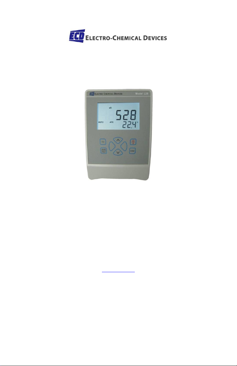
Model L20C
Instruction Manual
Microprocessor based
Conductivity TDS Temperature
Bench Top Meter
Electro-Chemical Devices, Inc.
1681 Kettering, Irvine, CA 92614 USA
Telephone: +1-949-336-6060
FAX: +1-949-336-6064
www.ecdi.com
Page 2

Contents
General Introduction .................................... 3
Initial Inspection ........................................... 3
Power ............................................................ 3
Installing the Batteries .................................................. 4
Display and Key Functions ............................ 5
A. Display ...................................................................... 5
B. Keys ........................................................................... 6
Operational Procedures................................ 7
A. Preparing Standard Solutions ................................... 7
B. Calibration ................................................................ 7
TDS Constant ............................................................ 7
Temperature Coefficient .......................................... 8
Temperature Reference ........................................... 8
Probe Basic Cell Constant ......................................... 8
Cell Constant Calibration .......................................... 8
K Value Input ............................................................ 9
C. Conductivity Measurements .................................... 9
Error Displays and troubleshooting ............ 10
Specifications .............................................. 11
Warranty ..................................................... 12
2
Page 3

General Introduction
Thank you for selecting the Model L20C meter. The Model L20C is a
precision tool that measures Conductivity, TDS and Temperature. A
built-in microprocessor stores, calculates and compensate for all
parameters related to Conductivity, TDS and Temperature
determinations.
This meter has a waterproof IP54 case. The mechanical keys are
highly reliable with tactile and audio feedback. This meter is
powered by six AAA-size alkaline batteries or with a UL approved AC
adapter (OUTPUT: DC9V). The meter also displays a “BAT” message
when the batteries are in need of replacement. Re-calibration is not
required when power is restored. The front of the meter has a large
LCD that displays Conductivity or TDS and Temperature
simultaneously along with user prompts and mode indicators. The
unit prompts the user through calibration and measurement
procedures. The Model L20C micro-processor allows the user to
easily recalibrate the parameters for the probe. A few keystrokes
will adjust all the parameters for conductivity and will also give the
user the option to select four types (0.01, 0.1, 1.0, 10.0) of probe cell
constant for a better selection of available probes and applications.
And the user can input K value of the cell by keypad directly. The
system simultaneously displays temperature in ℃ along with either
Conductivity or TDS. The user can switch back and forth from all
these displays by just pushing a single “MODE” key. Other
features include automatic conductivity ranging, automatic
temperature compensation, long battery life, and 50/60 Hz AC noise
rejection. This meter is user-friendly for laboratory application.
Initial Inspection
Carefully unpack the unit and accessories. Inspect for damages made
in shipment. If any damage is found, notify your ECD representative
immediately. All packing materials should be saved until satisfactory
operation is confirmed.
Power
The model EC3175 can be powered by an 115V or 230VAC adaptor
as well as 6 “AAA” alkaline batteries. Check the label on the AC
adaptor supplied with the instrument to make sure that the AC line
3
Page 4
voltage is correct. If the wrong AC adaptor is supplied, notify your
ECD representative immediately.
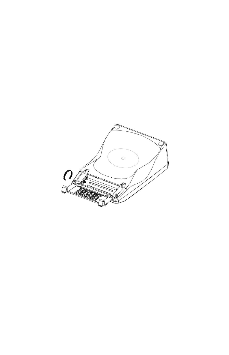
Installing the Batteries
To insert the batteries into the meter, follow the procedure outlined
below.
1.Use two hands to flip the two buckles and battery cover to expose
the battery compartment. (Figure 1)
2.Note the polarity and insert the six AAA batteries into the battery
compartment correctly.
3.Replace the battery cover.
Figure 1
4
Page 5

1. mS-
Conductivity measurement
7. mg/L-
TDS measurement
2. BAT-
8. CELL K=
Constant value
3. uS-
Conductivity measurement
9. %/°C-
compensation coefficient
4. CAL-
calibration mode
10. Main Display
5. AUTO-
11. Secondary Display
temperature
6. ATC/MAN-
MAN, indicates Uncompensated Conductivity reading
Display and Key Functions
A. Display
Figure 2
millisiemens, indicates
Low Battery Indicator
Microsiemens, indicates
Displayed when the
Instrument enters into the
Auto ranging indicator
ATC, indicates Automatic Temperature Compensation
Milligrams/Liter indicates a
Indicates conductivity Cell
Indicates the temperature
Numeric values for TDS or
Conductivity
Numeric values for
5
Page 6

B. Keys
On/Off-
the backlight.
Mode-
accidental erasing stored memory.
Press and hold this key for 5 seconds to power
on and shut off the meter. Once the unit is
powered up, press the same key to turn on or off
Cal-
During normal operation, this key will change the
mode from “Measure” mode to
“Calibration” mode.
Selects display mode. In normal operation, press
this key to sequentially display Compensated
Conductivity/Uncompensated Conductivity and
TDS.
Clear-
When this key is pressed, it clears all calibration
values stored in the internal memory.
Under normal use the key will not be activated
unless pressed and held for 5 seconds to prevent
Up/Down-
Increases or decreases the displayed value as
desired
Enter-
In Calibration mode, Press this key to save the
current parameter to memory.
6
Page 7

Operational Procedures
A. Preparing Standard Solutions
Suitable conductivity standards are available commercially or the
user can prepare them using research grade reagents. Here are
some standard solutions the user can prepare to calibrate the probe
of the Model L20C.
1. Standard solution of 1413uS at 25℃: Accurately weight
out 0.746 grams of research grade dried Potassium
Chloride (KCL). Dissolve in 1000ml of distilled water.
2. Standard solution of 12.90mS at 25℃: Accurately weight
out 7.4365 grams of research grade dried Potassium
Chloride (KCL). Dissolve in 1000ml of distilled water.
3. Standard solution of 111.9mS at 25℃: Accurately weight
out 74.264 grams of research grade dried Potassium
Chloride (KCL). Dissolve in 1000ml of distilled water.
Note: You can store the remaining solution in a plastic container for
one week but the air space between the cap and the solution must
be kept to an absolute minimum. Storing the excess solution below
4℃ can increase the storage life. If you have any doubt of the
accuracy of the stored solution, a fresh batch should be prepared.
B. Calibration
Calibration setup contains six sections: TDS Constant, Temperature
Coefficient, Temperature Reference, Probe Basic Cell Constant, Cell
Constant Calibration and K Value Input. To access these sections:
1. Connect the conductivity probe to the unit and turn the
unit on.
2. Allow temperature reading to stabilize, press “Cal” key
to enter the calibration mode. CAL appears on the LCD.
[Note: Press “Enter” key to accept any values changes in each
section and automatically advance to the next section. If there are
no changes, the unit accepts the current value and proceeds to the
next section.]
TDS Constant
TDS is determined by multiplying conductivity (mS) by a TDS factor.
The default factor value is 0.65. To change the TDS factor, use the
“up” and “down” keys to adjust the value between 0.30 and 1.00.
7
Page 8

Press “Enter” key to save the new value and go to the next
calibration parameter.
Temperature Coefficient
The unit uses the temperature coefficient to calculate temperature
compensated conductivity. The default value is
1.91%. To change the Temperature Coefficient, use the “up” and
“down” keys to adjust the value between 0 and 4.00%. Press
“Enter” key to save the new value and go to the next calibration
parameter.
Temperature Reference
The unit uses the temperature reference value to calculate
temperature compensated conductivity. The default value is 25℃.
To change the Temperature Reference, use the “up” and “down”
keys to adjust the value between 15 and 25℃. Press “Enter” key
to save the new value and go to the next calibration parameter.
Probe Basic Cell Constant
The main display shows the deviation of the conductivity probe
(calibrated previously or default, the deviation range is 70%~130%,
100% without error). The secondary display shows the current
selected cell constant. Using the “up” and “down” keys to adjust the
probe basic cell constant to that you use from the 4 available cell
constants (0.01, 0.1,1.0 and 10.0). Press “Enter” key to save the
new value and go to the next calibration parameter.
Cell Constant Calibration
1. Immerse the probe in a standard of known conductivity
solution (See section Preparing Standard Solutions),
preferably a standard in the middle range of the solutions
to be measured. Immerse the probe (at least 2” to 3” or
5~7cm from the tip) without touching the sides of the
calibration container. Shake the probe lightly to remove
any air bubbles trapped in the conductivity cell. The unit
will display the conductivity value of the standard solution.
During cell constant calibration, the following parameters
are over-ridden: temperature reference (fixed to 25.0℃)
and temperature coefficient (fixed to 1.91%). [Note: If you
8
Page 9

want input K value directly, please press the “Enter”
key to go to the K Value Input.]
2. Wait for the values of temperature and conductivity to
stabilize for a few seconds. Using the “up” and “down”
keys to adjust the reading of the display until it matches
the value of the known standard conductivity solution at
25℃.
3. Press “Enter” key to calculate and save the new value of
Cell Constant or press the “Enter” key to the next
calibration parameter.
K Value Input
1. The unit will display the conductivity value of the standard
solution with the CELL K= staying on. [Note: If the Cell
Constant has been calibrated, please press the “Enter” key
to exit calibration and return to normal operation.]
2. Press and hold the “up” or “down” key, the main display
will show the deviation of the conductivity probe. You can
now input the K value (from 70%~130% of the probe basic
cell constant). After releasing the up or down key, the unit
will display the conductivity value with the CELL K= staying
on.
3. Adjust the K value until the conductivity value displayed on
the LCD matches the value of the known standard
conductivity solution at 25℃.
4. Press “Enter” key to save the new K value of the cell to
exit calibration and return to normal operation mode.
C. Conductivity Measurements
1. Turn the unit on. Place the probe in the solution to be
measured. Immerse the probe (at least 2” to 3” or
5~7cm from the tip). Shake the probe lightly to remove
any trapped air bubbles in the conductivity cell.
2. Press “Mode” key to enter the desired measurement
mode (Conductivity or TDS). The message “over” or
“under” may appear briefly on the display indicate
auto-ranging; this is normal. Allow temperature to stabilize
before taking measurements.
9
Page 10

●Sample cannot be
constant value
●Sample cannot be
constant value
over
Sample temp. to high >
100°C
Reduce sample
temperature
Defective conductivity
cell
Replace conductivity
cell
undr
Sample temp. to
Low < 0.0°C
Increase sample
temperature
Defective conductivity
cell
Replace conductivity
cell
Error Displays and troubleshooting
Main
Display
“over”
During
measurement
“over”
During
calibration
“over”
During
calibration
“over”
During
measurement
Secondary
Display
0.0 - 100°C
0.0 - 100°C
0.0 - 100°C
Possible Causes
Sample conductivity
, >200 mS or 200
Conductivity cell
Incorrect cell constant
ue input
Conductivity cell
Incorrect cell constant
Corrective
Actions
tested
●Clean or replace cell
●Input correct cell
tested
●Clean or replace cell
●Input correct cell
10
Page 11

Specifications
Display
Range
Resolution
Accuracy
Conductivity
K=0.01
0.000 to 1.999uS/cm
2.00 to 19.99uS/cm
0.001uS/cm
0.01uS/cm
Conductivity
K=0.01
0.00 to 19.99uS/cm
2.0 to 199.9uS/cm
0.01uS/cm
0.1uS/cm
Conductivity
0.0 to 199.9uS/cm
2.00 to 19.99mS/cm
0.1uS/cm
0.01mS/cm
Conductivity
0 to 1999uS/cm
20.0 to 199.9mS/cm
1uS/cm
0.1mS/cm
Temperature
0.0 to 100.0 °C
0.1 °C ±0.2°C
±0.5% FS
±0.5% FS
K=0.01
K=0.01
200 to 1999uS/cm
2.00 to 19.99mS/cm
1uS/cm
0.01mS/cm
Reference Temperature
Temperature Coefficient 0.0% to 4.0%
Cell Constant 0.01; 0.10; 1.00; 10.0
TDS Constant Range 0.30 to 1.00, default at 0.65
Power
Calibration Back-up EEPROM
Audio Feedback All Touch Keys
Display 22mm : 14.5mm high LCD
Ambient Temperature
Relative Humidity up to 90%
Case IP54
Dimensions 150mm x 203mm x 72mm
Weight 504 grams(Batteries included)
15.0 to 25.0 °C
Six “AAA” Batteries
0 to 50 °C
±0.5% FS
±0.5% FS
11
Page 12

Warranty
Electro-Chemical Devices, Inc. (ECD) warrants all products it
manufactures to be free from defect in materials and factory
workmanship, and agrees to repair or replace any product that fails
to perform, as specified, within one (1) year after date of shipment.
This warranty shall not apply to any product that has been:
1. Subjected to misuse, negligence or accident;
2. Connected, installed, adjusted or otherwise used not in
accordance with the instructions furnished by ECD;
3. Repaired, modified or altered by persons not authorized
by ECD, resulting in injury to the performance, stability or
reliability of the product.
This warranty is in lieu of any other warranty, expressed or implied.
ECD reserves the right to make changes in the design or construction
of its products at any time, without prior notification, and without
incurring any obligation to make any changes in previously delivered
products.
Seller’s sole liabilities and the buyer’s sole remedies under this
agreement shall be limited to a refund in the purchase price, or at
ECD’s discretion, to the repair or replacement of any product that
proves, upon ECD’s examination, to be defective, when returned to
the factory, transportation prepaid by the buyer, within one (1) year
of the product’s original shipment date. Seller shall not be liable for
damages consequential or incidental to defects in any product, for
failure of delivery in whole or in part, for injuries resulting from its
use, or for any other cause.
This warranty and the writing attached constitute the full
understanding of seller and the buyer, and no terms, conditions,
understanding, or agreement purporting to modify or vary the terms
hereof shall be binding unless hereafter made in writing and signed
by an authorized official of Electro-Chemical Devices, Inc.
This warranty does not cover pH, ORP or Specific Ion measurement,
reference or combination electrodes or electrode cartridges that
have been commissioned in service.
If service or repair is required, please obtain the serial number(s) or
sales order number of the product(s) in question and contact ECD’s
Service Department at: +1-800-729-1333 (USA/Canada) or +1-949336-6060
12
 Loading...