

Page 1
ELECTRO-CHEMICAL DEVICES, INC.
DCA-23 Instruction Manual
Seawater Chlorination/Dechlorination Analyzer
ELECTRO-CHEMICAL DEVICES, INC.
1681 Kettering, Irvine, CA 92614, USA
Tel: +1-949-336-6060, FAX: +1-949-336-6064
www.ecdi.com
The information and technical data disclosed in this document may be used and disseminated only for the purposes and to the extent specifically
authorized in writing by Electro-Chemical Devices. Electro-Chemical Devices reserves the right to change published specifications and designs
without prior notice. Part No. 33DCA-23 Revision A
Rev: A - 03/11
Page 2

PREFACE
Purchasing products from Electro-Chemical Devices, Inc. provides you with the finest liquid analytical instrumentation
available. If this is your first purchase from ECD, please read this manual before installing and commissioning your new
equipment.
If there are any questions concerning this equipment, please contact your local ECD representative, or the factory
directly at:
Electro-Chemical Devices, Inc.
1681 Kettering
Irvine, CA 92614 USA
Telephone: +1-949-336-6060
FAX: +1-949-336-6064
Website: www.ecdi.com
Email: sales@ecdi.com
© 2010 Electro-Chemical Devices, Inc. All rights reserved. No part of this manual may be used or reproduced in any form or by any means, or stored in a database or
retrieval system without prior written permission from Electro-Chemical Devices, Inc. Making copies of any part of this manual for any purpose other than personal
use is a violation of United States copyright laws. Document printed in the United States of America.
Page ii DCA-23 Dechlorination Analyzer
Page 3

TABLE OF CONTENTS
PREFACE .................................................................................................................................................................................. ii
TABLE OF CONTENTS .............................................................................................................................................................. iii
WARRANTY.............................................................................................................................................................................. v
IMPORTANT SERVICE INFORMATION ..................................................................................................................................... v
UNPACKING THE INSTRUMENT .............................................................................................................................................. vi
1.0 GENERAL DESCRIPTION ..................................................................................................................................................... 1
1.1 Features ........................................................................................................................................................................ 2
1.2 Specifications ................................................................................................................................................................ 2
2.0 INSTALLATION ................................................................................................................................................................... 4
2.1 MOUNTING ................................................................................................................................................................... 4
2.2 WIRING .......................................................................................................................................................................... 5
2.2.1 Wiring, Sensor(s) .................................................................................................................................................... 5
2.2.2 Wiring, power ........................................................................................................................................................ 5
2.2.3 Wiring, 4-20 mA Outputs ....................................................................................................................................... 5
2.2.4 Wiring, Contact Relay Outputs ............................................................................................................................... 5
2.3 PLUMBING ..................................................................................................................................................................... 6
2.3.1 Sample Requirements ............................................................................................................................................ 6
2.3.2 Connecting the Inlet and Drain fittings .................................................................................................................. 6
2.4 INSTALLING the SENSORS ............................................................................................................................................. 6
3.0 OPERATION ....................................................................................................................................................................... 7
3.01 Measurement Overview ......................................................................................................................................... 7
Table #1 TRO/pH/Equivalent Chlorine ppm .................................................................................................................... 7
3.1 KEYS ............................................................................................................................................................................... 8
3.2 MENUS .......................................................................................................................................................................... 8
3.2.1 TRO Menus ............................................................................................................................................................. 8
3.2.2 pH Menus ............................................................................................................................................................... 9
3.3 CALIBRATION MENUS ................................................................................................................................................. 11
3.3.1 pH Calibration ...................................................................................................................................................... 11
3.3.2 TRO Calibration .................................................................................................................................................... 11
3.3.3 Temperature Trim ................................................................................................................................................ 11
DCA-23 Page iii
Page 4

3.4 OUTPUTS (4-20 mA Channels) ................................................................................................................................ 12
3.4.1 pH Output ............................................................................................................................................................ 12
3.4.2 Chlorine Output ................................................................................................................................................... 12
3.4.3 Manual Mode (4-20 mA Hold Function) .............................................................................................................. 12
3.5 ALARM RELAYS ............................................................................................................................................................ 13
3.5.1 Chlorine Alarm Relay ............................................................................................................................................ 13
3.5.2 pH Alarm Relay ..................................................................................................................................................... 13
4.0 START UP ......................................................................................................................................................................... 14
4.1 CALIBRATION ............................................................................................................................................................... 14
4.2 TEMPERATURE SENSOR .............................................................................................................................................. 14
4.3 pH SENSOR .................................................................................................................................................................. 14
4.3.1 Two Point Calibration ........................................................................................................................................... 14
4.4 CHLORINE SENSOR (TRO) ............................................................................................................................................ 14
4.4.1 TRO Calibration Example...................................................................................................................................... 15
5.0 MAINTENANCE ................................................................................................................................................................ 16
5.1 Chlorine TRO Sensor ................................................................................................................................................... 16
5.2 pH Sensor .................................................................................................................................................................... 16
6.0 TROUBLESHOOTING ........................................................................................................................................................ 17
7.0 ORDERING INFORMATION .............................................................................................................................................. 18
7.1 ACCESSORIES and SPARE PARTS ................................................................................................................................. 18
8.0 ENGINEERING DOCUMENTATION ................................................................................................................................... 19
8.1 SPECIFICATIONS .......................................................................................................................................................... 19
8.2 OUTLINE & DIMENSIONAL DRAWING ......................................................................................................................... 21
PN 1290220 ................................................................................................................................................................... 21
8.3 WIRING DIAGRAMS ..................................................................................................................................................... 21
PN 1290220-1 ................................................................................................................................................................ 21
PN 1290220-2 ................................................................................................................................................................ 22
PN 1290220-3 ................................................................................................................................................................ 22
PN 1290220-4 ................................................................................................................................................................ 23
PN 1290220-5 ................................................................................................................................................................ 23
Page iv DCA-23 Dechlorination Analyzer
Page 5

WARRANTY
Electro-Chemical Devices, Inc. (ECD) warrants all products it manufactures to be free from defect in materials and factory workmanship, and agrees
to repair or replace any product that fails to perform, as specified, within one (1) year after date of shipment. This warranty shall not apply to any
product that has been:
1. Subjected to misuse, negligence or accident;
2. Connected, installed, adjusted or otherwise used not in accordance with the instructions furnished by ECD;
3. Repaired, modified or altered by persons not authorized by ECD, resulting in injury to the performance, stability or reliability of the
product.
This warranty is in lieu of any other warranty, expressed or implied. ECD reserves the right to make changes in the design or construction of its
products at any time, without prior notification, and without incurring any obligation to make any changes in previously delivered products.
Seller’s sole liabilities and the buyer’s sole remedies under this agreement shall be limited to a refund in the purchase price, or at ECD’s discretion,
to the repair or replacement of any product that proves, upon ECD’s examination, to be defective, when returned to the factory, transportation
prepaid by the buyer, within one (1) year of the product’s original shipment date. Seller shall not be liable for damages consequential or incidental
to defects in any product, for failure of delivery in whole or in part, for injuries resulting from its use, or for any other cause.
This warranty and the writing attached constitute the full understanding of seller and the buyer, and no terms, conditions, understanding, or
agreement purporting to modify or vary the terms hereof shall be binding unless hereafter made in writing and signed by an authorized official of
Electro-Chemical Devices, Inc.
This warranty does not cover pH, ORP or Specific Ion measurement, reference or combination electrodes or electrode cartridges that have been
commissioned in service.
IMPORTANT SERVICE INFORMATION
Use only factory authorized components for repair. Tampering or unauthorized substitution of components may adversely affect the
operation of this product and may void the warranty.
If service or repair is required, please obtain the serial number(s) or sales order number of the product(s) in question and contact
ECD’s Service Department at:
+1-800-729-1333 (USA/Canada) or +1-949-336-6060
or email Service@ecdi.com
A Return Material Authorization (RMA) number must be obtained from the service department before returning any material to
ECD. All material returned to ECD shall be shipped prepaid to the factory.
DCA-23 Page v
Page 6

UNPACKING THE INSTRUMENT
Your Electro-Chemical Devices instrument has been carefully packaged to protect it from damage during shipment and
dry storage. Upon receipt please follow the procedure outlined below.
1. Before unpacking, inspect the condition of the shipping container to verify proper handling by the carrier. If
damage is noted, save the shipping container as proof of mishandling for the carrier.
2. Check the contents of the shipping container with the items and quantities shown on the packing list.
Immediately report any discrepancies to ECD.
3. Save the original packing material until you are satisfied with the contents. In the event the product(s) must be
returned to ECD, the packing material will allow you to properly ship it to ECD.
4. Familiarize yourself with the instrument before installation, and follow proper installation and wiring
procedures.
Page vi DCA-23 Dechlorination Analyzer
Page 7
1.0 GENERAL DESCRIPTION
The Model DCA-23 is a single purpose analyzer designed to
monitor the chlorination and/or dechlorination of seawater in
the range of 0.00 - 2.00 ppm.
Sea water is used for cooling in power plants, refineries and
SWAC systems (salt water air conditioning). The heat
exchangers on LNG terminals use large quantities of sea
water in the regasification process. Sea water is also
chlorinated and de-chlorinated at desalination plants. The
chlorination of sea water inhibits the growth of marine life on
the various filters, screens and heat exchange surfaces that the sea water passes over. Before the
chlorinated water is returned to the environment it must be dechlorinated to a level acceptable to the
local authorities.
Sea water contains approximately 68 mg/L of bromide. When chlorine is added to sea water, the
bromide ion is oxidized to hypobromous acid (HOBr) and hypobromite (OBr-) by the Free Chlorine (HOCl
and OCl-). This is a very rapid reaction and essentially all of the chlorine is instantaneously converted
into bromine and bromamines. The DCA-23 displays Chlorine ppm in order to conform to existing
conventions. It actually measures the temperature, pH and Total Residual Oxidant (TRO) potential of the
seawater and converts them into an equivalent “ppm chlorine” value. TRO is defined as the total
oxidizing capacity (free and combined) of the sea water that is available after chlorination.
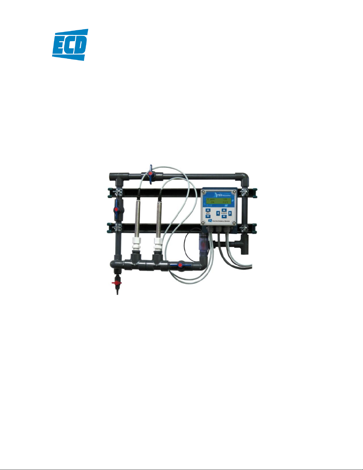
The Model DCA-23 analyzer is supplied as a fully assembled rack mounted system. The ¾” schedule 80
PVC pipe flow through assembly is configured with ¾” slip fittings on both the Input and Drain ends. The
flow through assembly and the T23 Analyzer/Transmitter are mounted on two 1 ⅝” x 1 ⅝” Uni Strut rails
pre-drilled with two 0.38” holes 24” apart and with 6” between the Struts. The Standard Configuration
allows the sample to flow through either the measurement loop or the bypass loop depending on the
valve orientations. The pH sensor and TRO sensor are pre-wired into the analyzer allowing for easy
installation and Start Up of this measurement system. Simply mount the DCA-23 assembly to a wall,
plumb the Input and Drain lines, connect the power and output wiring and the system is up and running.
DCA-23 Page 1
Page 8

1.1 Features
• Uni Strut Rail Mounted System, Easy Installation
• Plumb and Play Design, Ready to Use
• Not Flow Sensitive, Eliminates Pressure Regulators and Rotameters
• Direct Chlorine Readout, pH and Temperature compensated
1.2 Specifications
Sensor and Flow Train
TRO Sensor:
Platinum Indicator/Silver-Silver chloride Reference, PTFE junction
0.75” OD x 10.5” length, Internal Signal Conditioning
pH Sensor:
Glass Indicator/Silver-Silver chloride Reference, PTFE junction
0.75” OD x 10.5” length, Internal Signal Conditioning
Measurement Range:
Chlorine: 0.00 to 2.00 ppm
pH: 0 to 14 pH
Operating Temperature:
0° C to 60° C (32° F to 140° F)
Operating Pressure:
0-50 psig at 60° C
Wetted Materials:
PVC, PP, PTFE, Glass, Platinum, 316 SS
Process Connections:
Input: ¾” NPT Slip fitting,
Drain: ¾” NPT Slip fitting
Response Time:
T90 in 2 minutes
C22 Analyzer:
Measurements:
Chlorine: 0.01 to 2.00 ppm
pH: 0 to 14 pH
Temperature: 0° C to 100° C (32° F to 212° F)
pH Compensation:
Automatic
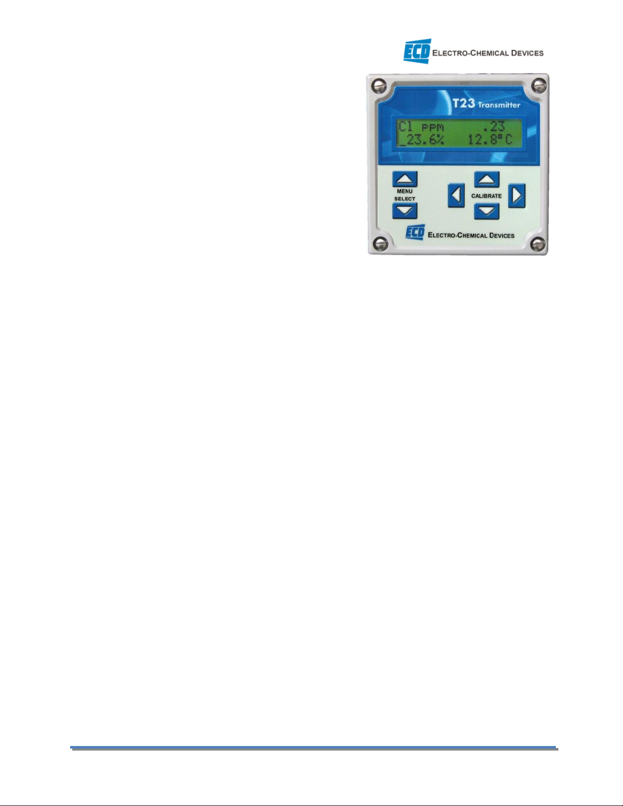
Display:
4” X 1” LCD, 2 x 16 characters
Enclosure:
NEMA 4X, LxWxD: 5.7” x 5.7” x 7
Outputs:
(1) 4-20 mA for Chlorine (set to Sensors Range, 0-2.00 ppm or 0-1.00 ppm)
Page 2 DCA-23 Dechlorination Analyzer
Page 9

(1) 4-20 mA for pH (Optional) set 0-14 pH
Alarm Relay Ratings:
Optional (2) SPDT 230 VAC/5A or 30 VDC / 5A resistive max.
Standard Configuration (1) High Alarm Chlorine, (1) Low Alarm Chlorine, (User adjusted Set Points)
(Optional User Defined configuration, Configurable at the Factory Only)
Input Power
24 VDC (12 to 50 VDC) @ 0.25A
Optional 110/220 VAC @ 50/60 Hz
DCA-23 Page 3
Page 10

2.0 INSTALLATION
Mount the DCA-23 in a location where there is easy access to the analyzer and sensors. Install the
system in an area where vibrations, electromagnetic and radio frequency interference are minimized or
absent.
Do not mount in direct sunlight or areas of extreme heat. The DCA-23 is suitable for outdoor use if
mounted with a protective cover or sunshield. (Consult with Factory)
2.1 MOUNTING
The DCA-23 Uni-Strut Rails are drilled with 4 x 0.38” holes, one at each corner.
Page 4 DCA-23 Dechlorination Analyzer
Page 11

2.2 WIRING
Electrical wiring should only be conducted by qualified personnel. See the wiring color code for the DCA23 in Section 8.3 below.
2.2.1 Wiring, Sensor(s)
The TRO Sensor and the PHS10 pH Sensor were connected to the T-23 transmitter at the factory, no
additional connections are necessary. Color coded connections for these sensors are shown in the wiring
diagrams in Section 8.3 or inside the cover of the T-23 analyzer.
2.2.2 Wiring, power
Attach power cable, either 110/220 VAC or 24 VDC, as shown in the diagram in Section 8.3 or inside of
the T-23 cover. Feed the cable through the gland fitting on the right hand side of the T-23. Tighten the
cable gland to provide a good seal to the cable. The instrument can be powered up at this point with no
harm to the analyzer but it is best to wait until the sensors are installed.
2.2.3 Wiring, 4-20 mA Outputs
The 4-20 mA outputs are unpowered outputs, 24V can be supplied from an external source (loop
powered), i.e. the PLC or DCS or from the optional internal PS10/11 power supply.
If the internal PS10/11 Power Supply is used, follow the wiring diagram in Section 8.3 for the particular
instrument.
If the 4-20 mA loop is powered from an external source then simply connect a shielded 22 gauge twisted
pair communication wire to Terminals #1 and #2 of the 4-20 mA terminal.
The standard configuration has Chlorine (TRO) on mA 1 and (optional) pH on mA 2.
2.2.4 Wiring, Contact Relay Outputs
This optional configuration has two SPDT 230V 5 A relays that can be wired either normally open (NO) or
normally closed (NC). The default configuration is set to use the relays as normally open.
Relays 1&2
Wire Relays as a NO relay. (See diagram in Section 8.3) The Relays are alarm relays and should be
connected to the Control System or an external alarm.
Do not run the Alarm Relay cable through the same cable gland fitting as the electrodes or the 4-20 mA
signals.
DCA-23 Page 5
Page 12

2.3 PLUMBING
2.3.1 Sample Requirements
Sample Pressure: 1 to 50 psig (0.1 – 3.4 bar)
Temperature: 32° to 140°F (0° to 60°C)
2.3.2 Connecting the Inlet and Drain fittings
The DCA-23 is intended for wall mounting only.
Sample Inlet:
A ¾” pipe slip fitting is provided for the sample inlet.
Sample Drain:
The sample drains through the ¾” pipe slip fitting.
The sample can be introduced after the sensors have been calibrated and installed in the flow cells.
2.4 INSTALLING the SENSORS
The DCA-23 is supplied with the sensor cables pre-wired to the analyzer. The DCA-23 instrument and
sensors were calibrated at the factory and should be ready for use when assembled. However, changes
may have occurred during shipping and storage requiring recalibration. (See Calibration section below)
The TRO sensor mounts in the Flow Cell using the supplied ¾” compression gland fitting. Remove the
protective cap from the sensor and save it for future use, the cap contains a potassium chloride solution
use care when removing the cap from the sensor. Loosen the compression fitting to allow the sensor to
spin freely in the fitting. Insert the sensor into the flow cell using a twisting motion. There are o-ring
seals inside the fitting the twisting motion will facilitate passing these seals. Slide the sensor to the
bottom of the flow cell and then retract the pH sensor approximately ½” from the bottom of the flow
cell and hand tighten the compression nut to fix its position.
The pH sensor mounts in the Flow Cell using the supplied ¾” compression gland fitting. Remove the
protective cap from the sensor and save it for future use, the cap contains a potassium chloride solution
use care when removing the cap from the sensor. Loosen the compression fitting to allow the sensor to
spin freely in the fitting. Insert the sensor into the flow cell using a twisting motion. There are o-ring
seals inside the fitting the twisting motion will facilitate passing these seals. Slide the sensor to the
bottom of the flow cell and then retract the pH sensor approximately ½” from the bottom of the flow
cell and hand tighten the compression nut to fix its position.
Page 6 DCA-23 Dechlorination Analyzer
Page 13

3.0 OPERATION
This section will provide a basic overview of the DCA-23 Analyzer. It covers the basic Menu structure and
the functions of the MENU SELECT keys and the CALIBRATE keys.
3.01 Measurement Overview
Sea water contains approximately 68 mg/L of bromide. When chlorine is added to sea water, the
bromide ion is oxidized to hypobromous acid (HOBr) and hypobromite (OBr-) by the Free Chlorine (HOCl
and OCl-). This is a very rapid reaction and essentially all of the chlorine is instantaneously converted
into bromine and bromamines. The DCA-23 measures the temperature, pH and Total Residual Oxidant
(TRO) potential of the seawater and converts them into an equivalent “ppm chlorine” value, using the
stored TRO/pH/Cl ppm table, see below. Even though there is no chlorine present, the DCA-23 displays
Chlorine ppm in order to conform to existing conventions. TRO is defined as the total oxidizing capacity
(free and combined) of the sea water that is available after chlorination.
Table #1 TRO/pH/Equivalent Chlorine ppm
DCA-23 Page 7
Page 14

Screen Displayed
Button Pressed
Cl ppm
.23
Home Screen
(view only)
TRO 526.9
mV
TRO Screen
(view only)
Input 520.5 mVa
TRO Raw Input Screen
(view
only)
1 TRO 180.0 mV
TRO Cal
ibration
1 Screen
2 TRO 0.0 mV
TRO Cal
ibration
2
Screen
4 mA .00 ppm
Chlorine
4-
20 mA
Adjustment screen
ON .00 ppm
Chlorine Alarm Relay
Adjustment screen
3.1 KEYS
The blinking cursor indicates the active point where menus can be selected or numerical values
adjusted. There are two sets of keys on the DCA-23 analyzer, the MENU SELECT keys and the CALIBRATE
keys.
The MENU SELECT keys are used to move the cursor vertically changing the displayed menu. These keys
are also used to Save/Accept the calibration data and exit the calibration menu.
The CALIBRATE keys are used to enter menus, change numerical values and move the cursor.
To enter a calibration menu or parameter adjustment line, simultaneously press both of the
Horizontal CALIBRATE keys, ◄CALIBRATE►
Pressing either of the Horizontal CALIBRATE keys separately will move the cursor horizontally to the
point under the digit to be adjusted. The Vertical CALIBRATE keys are used to adjust numeric values.
Pressing the upper key will increase the value and pressing the lower key will decrease the value.
3.2 MENUS
There are two sets of menus on the Model DCA-23. The Channel 1 menus (PV1) are the TRO menus, the
Channel 2 menus (PV2) are the pH menus. Pressing the MENU SELECT Down key will access the pH
channel, pressing the MENU SELECT Up key will access the TRO channel. See the guide below for the
general menu structure.
3.2.1 TRO Menus
23.6% 12.8°C
12.8°C
0 mVa 6.4 mV
Cal 173.5 mVa
Cal 1.000 mV/TRO
20 mA 1.00 ppm
OFF .00 ppm
Press MENU SELECT ▲ to move to TRO Screen
MENU SELECT ▲
MENU SELECT ▲
MENU SELECT ▲
MENU SELECT ▲
MENU SELECT ▲
MENU SELECT ▲
Page 8 DCA-23 Dechlorination Analyzer
Page 15

Contrast 20
Contrast Adjustment screen
Screen Displayed
Button Pressed
Cl ppm .23
Home Screen
(view only)
pH 7.35
pH Screen
(view only)
Input
-
20.0 mVa
pH Raw Input Screen
(view only)
MENU SELECT ▼….. To return to the Home screen
3.2.1.1 Home Screen
The Home Screen displays the calculated Chlorine value and engineering units, Chlorine ppm, the % 4-20
mA output and the temperature.
3.2.1.2 TRO Screen
The TRO Screen displays the TRO mV value used to calculate the displayed chlorine ppm value.
3.2.1.3 TRO Raw Input Screen
The TRO Raw Input Screen displays the actual TRO signal from the sensor on line 1 and the amount of
zero point correction applied on line 2. (Actual TRO + ZP Correction = TRO)
3.2.1.4 TRO Cal 1 Screen
The TRO Calibration 1 Screen is an ENTRY screen. To calibrate the system Enter the TRO mV value that
corresponds to the DPD determined Chlorine value from the calibration chart.
3.2.1.5 TRO Cal2 Screen
The TRO Calibration 2 Screen is an ENTRY screen. This is a slope correction screen, mV/TRO. In all cases
this screen should be set to the default value 1.000 mV/TRO.
3.2.1.6 Chlorine 4-20 mA Screen
The Chlorine 4-20 mA Screen is an ENTRY screen. Set the range of the 4-20 mA output in this screen.
Default is 0.00 ppm – 2.00 ppm = 4-20 mA.
3.2.1.7 Chlorine Alarm Relay Screen (optional)
The Chlorine Alarm Relay screen is an ENTRY screen. This allows the alarm relay to be configured as High
or Low Set Point (ON) and hysteresis value (OFF).
3.2.1.8 Contrast Screen
The Contrast screen allows for the adjustment of the screen contrast.
3.2.2 pH Menus
23.6% 12.8°C
52.5% 12.8°C
0 mVa 7.00
MENU SELECT ▼
MENU SELECT ▼
MENU SELECT ▼
DCA-23 Page 9
Page 16

1 pH 7.00
pH Cal 1 Screen
2 pH 10.01
pH Cal 2
Screen
4 mA .00
pH 4-
20 mA Adjustment screen
ON .00 pH
pH Alarm Relay
Adjustment screen
Trim °C .0
Temperature Trim/ Units Screen
Cal .0 mV@25
Cal -59.1 mV/pH
20 mA 14.00
OFF .00 pH
Unit 12.8°C
MENU SELECT ▼
MENU SELECT ▼
MENU SELECT ▼
MENU SELECT ▼
MENU SELECT ▲….. To return to the Home screen
3.2.2.1 Home Screen
The Home Screen displays the calculated Chlorine value and engineering units, Chlorine ppm, the % 4-20
mA output and the temperature.
3.2.2.2 pH Screen
The pH Screen displays the pH value, the % mA output and the temperature.
3.2.2.3 pH Raw Input Screen
The pH Raw Input Screen displays the actual mV signal from the pH sensor on line 1 and the amount of
zero point correction applied on line 2.
3.2.2.4 pH Cal 1 Screen
The pH Calibration 1 Screen is an ENTRY screen. This is a zero point calibration screen, use pH 7.00
buffer to set the zero point, also used to standardize the reading.
3.2.2.5 pH Cal 2 Screen
The pH Calibration 2 Screen is an ENTRY screen. This is a slope correction screen, mV/pH. Use pH 10
buffer to set the slope. The default value is -59.1 mV/pH.
3.2.2.6 pH 4-20 mA Screen(optional)
The pH 4-20 mA Screen is an ENTRY screen. Set the range of the 4-20 mA output in this screen. Default is
0.00 pH – 14.00 pH = 4-20 mA.
3.2.2.7 pH 4-20 mA Screen(optional)
The pH Alarm Relay screen is an ENTRY screen. This allows the alarm relay to be configured as High or
Low Set Point (ON) and hysteresis value (OFF).
3.2.2.8 Temperature Trim and Units Screen
The Temperature Trim allows the temperature to be adjusted, removing inaccuracies from extended
cable lengths. Units, °C or °F are also set in this menu.
Page 10 DCA-23 Dechlorination Analyzer
Page 17
Screen Displayed
Button Pressed
1 pH
7.00 pH
Cal
.0 mV
CALIBRATE
(enter
s calibration
line
, zero pt. Cal 1)
Sensor should be in a 7.0 pH solution.
1
pH 7
.00 pH
Cal
0.2 mV
MENU SELECT
(accept
s the
Calibration
when the mV
value is stable
)
1 pH
7.00 pH
Cal
0.2 mV
MENU SELECT
(move
down
to Cal line)
(Entering the Cal line resets value to 0.0 mV)
1 pH
7.00 pH
C
al
0.2 mV
MENU SELECT
(move to Cal 2, Slope)
Remove and rinse sensor with distilled water
2 pH 10
.00 pH
C
al
59.1
mV
/pH
CALIBRATE
(enter
Cal Line
)
Place Sensor in a pH 10.00 solution
2
pH 10
.00 pH
C
al
60.2
mV
/pH
Set the pH v
alue us
ing the CALIBRATE
or ►
to move
cursor. Use the
to adjust the integer value.
2
pH
1
0.00 pH
C
al
60.2
mV
/ppm
MENU SELECT
(accept Calibration)
2 pH 10.00
pH
C
al
60.2
mV
/ppm
MENU SELECT
(return to Home Screen)
Screen Displayed
Button Pressed
1 TRO
180.0 mV
Cal
173.4
mVa
Run DPD test on Sample, Determine TRO value from
Calibration Curve using DPD Value and pH
1 TRO
180.0 mV
Cal
173.4
mVa
press
CALIBRATE
to initiate
Calibration.
1
TRO 526.0 mV
Cal
519.0
mVa
Enter the
TRO Value us
ing the CALIBRATE
or ►
to move
cursor. Use the
to adjust the integer value.
1 TRO
526.0 mV
Cal
519.0
mVa
MENU SELECT
(accept Calibration)
2
TRO
.00 mV
C
al
1.000
mV
/TRO
MENU SELECT
Verify slope 1.000 mV/TRO
2
TRO
.00 mV
C
al
1.000
mV
/TRO
CALIBRATE
(enter
Cal Line
)
Resets value to factory Default: 1.000 mV/TRO
2 TRO
.00 mV
C
al
1.000
mV
/TRO
MENU SELECT
(return to Home Screen)
Screen Displayed
Button Pressed
Trim °C .0
Unit 12.8°C
press
CALIBRATE
to initiate
Calibration.
Trim °C
2.4
Unit 1
5.2°C
Enter the
Temp
Value us
ing the CALIBRATE
or ►
to
move cursor. Use the
to adjust the integer value.
3.3 CALIBRATION MENUS
3.3.1 pH Calibration
3.3.2 TRO Calibration
◄
◄
►
▼
▼
▼
►
◄
▲or▼
▼
▲
3.3.3 Temperature Trim
◄
◄
◄
►
◄
▲or▼
▲
▲
►
▼
►
◄
▲or▼
DCA-23 Page 11
Page 18

Screen Displayed
Button
Pressed
4mA1
2.00 pH
CALIBRATE
►
(enter 4mA line)
4mA1
0.00 pH
To adjust the value
use the CALIBRATE
or ►
to move
4mA1
0.00 pH
MENU SELECT
(accept the Value)
4mA1
0.00 pH
MENU SELECT
4mA1
0.0 pH
CALIBRATE
►
(enter 20mA line)
4mA1
0.0 pH
To adjust the value
use the CALIBRATE
or ►
to move
4mA1
0.0 pH
MENU SELECT
(accept the Value)
4mA1
0.0 pH
MENU SELECT
(Return to Home Screen)
Screen Displayed
Button Pressed
4mA1
0.00 ppm
CALIBRATE
►
(enter
20
mA line)
4mA1
0.00
ppm
To adjust the value
use the CALIBRATE
or ►
to move
4mA1
0.00 ppm
MENU SELECT
(accept the Value)
3.4 OUTPUTS (4-20 mA Channels)
The DCA-23 has one 4-20 mA output configured for 0-2.00 ppm Chlorine. An optional second 4-20 mA
output for pH is available.
3.4.1 pH Output
◄
20mA1 12.00 pH
◄
20mA1 12.00 pH
20mA1 12.00 pH
20mA1 12.00 pH
20mA1 12.00 pH
20mA1 12.00 pH
20mA1 14.00 pH
20mA1 14.00 pH
cursor. Use the ▲or▼ to adjust the integer value.
▼
▼
◄
◄
cursor. Use the ▲or▼ to adjust the integer value.
▼
▲
(4-20 mA1 is set to 0.00 pH to 14.00 pH)
3.4.2 Chlorine Output
◄
20mA1 1.00 ppm
◄
20mA1 2.00 ppm
20mA1 2.00 ppm
3.4.3 Manual Mode (4-20 mA Hold Function)
The % Output values are displayed on the Home Screen for the Cl ppm output, mA 1, and in the pH
Screen for the optional pH Output, mA 2.
The outputs can be set to manual control by simultaneously pressing both horizontal CALIBRATE keys
when the cursor is in front of the % Output line. An “M” will be displayed in front of the % Output value.
The Output will remain frozen at the last value until the Manual Mode is turned off. The Manual Mode
hold function is commonly used to freeze the outputs during maintenance and calibration cycles. While
in Manual Mode the Output can be adjusted between 0 and 99.9% using the CALIBRATE keys, very
useful for troubleshooting loop communication problems.
To exit Manual Mode press the left CALIBRATE arrow, ◄, three times and the “M” will disappear, the
Output will return to a live reading.
cursor. Use the ▲or▼ to adjust the integer value.
▼
Page 12 DCA-23 Dechlorination Analyzer
Page 19

Screen Displayed
Button Pressed
1 On > .0 ppm
CALIBRATE
►
(enter Relay Set Point)
1 On > .
0
ppm
To adjust the value
use the CALIBRATE
or ►
to move
1 On >
2
.00 ppm
MENU SELECT
(accept the Value)
1 On > 2.
0
0 ppm
MENU SELECT
1
On > 2.0
0
ppm
CALIBRATE
►
(enter Relay Hysteresis Point)
1 On
>
2.00
ppm
To adjust the value
use the CALIBRATE
or ►
to move
1 On
<
2.00
ppm
MENU SELECT
(accept the Value) ** Whether the relay is
1 On
> 2.00
ppm
(High Alarm
MENU SELECT
(If the Off value is
below the set point
Screen Displayed
Button Pressed
1 On > .0 pH
CALIBRATE
►
(enter Relay Set Point)
1 On > .
0
pH
To adjust the value
use the CALIBRATE
or ►
to move
1 On >
8
.50 pH
MENU SELECT
(accept the Value)
1 On > 8.50 pH
MENU SELECT
1
On > 8.5
0
pH
CALIBRATE
►
(enter Relay Hysteresis Point)
1 On
>
8.50 pH
To adjust the value
use the CALIBRATE
or ►
to move
1 On
<
8.50 pH
MENU SELECT
(accept the Value) ** Whether the relay is
1 On
> 8.50
pH
(High Alarm
MENU SELECT
(If the Off value is
below the set point
3.5 ALARM RELAYS
The DCA-23 has an option of two alarm relays. Relay 1 is set as an alarm on PV1 the Chlorine channel.
Relay 2 is set for an alarm on the pH channel. The relays can be wired as NO, Normally Open or NC,
Normally Closed. The default configuration assumes NO status.
3.5.1 Chlorine Alarm Relay
◄
1 Off < .0 ppm
◄
1 Off < .0 ppm
1 Off < .0 ppm
1 Off < .0 ppm
1 Off < .0 ppm
1 Off < .0 ppm
1 Off > 1.75 ppm
1 Off < 1.75 ppm example)
1 On < 1.00 ppm (Low Alarm
1 Off > 1.15 ppm example)
cursor. Use the ▲or▼ to adjust the integer value.
▼
▼
◄
◄
cursor. Use the ▲or▼ to adjust the integer value.
▼
a High or Low Alarm is determined by the Off value **
▼
then the relay will be a High Alarm, closing at 2.00 ppm and
re-opening below 1.75 ppm. If the Off is above the set point
the relay will switch to a Low Alarm.)
3.5.2 pH Alarm Relay
1 Off < .0 pH
1 Off < .0 pH
1 Off < .0 pH
1 Off < .0 pH
1 Off < .0 pH
1 Off < .0 pH
1 Off > 8.45 pH
1 Off < 8.45 pH example)
1 On < 1.00 pH (Low Alarm
1 Off > 1.15 pH example)
◄
◄
cursor. Use the ▲or▼ to adjust the integer value.
▼
▼
◄
◄
cursor. Use the ▲or▼ to adjust the integer value.
▼
a High or Low Alarm is determined by the Off value **
▼
then the relay will be a High Alarm, closing at 8.50 pH and
re-opening below 8.45 pH. If the Off is above the set point
the relay will switch to a Low Alarm.)
DCA-23 Page 13
Page 20

4.0 START UP
Supply sample flow to the system. Verify the sample flow is passing through both flow cells and
returning to the drain. The S10 style sensors tend to self purge air from the flow cell naturally and
usually don’t require any special treatment. Purge any trapped air in the system by loosening the
electrode fitting allowing water to overflow out of the Tee Flowcell.
Allow the system to run at least 1 hour before proceeding to the Chlorine/TRO Sensor calibration.
4.1 CALIBRATION
The DCA-23 was calibrated before shipping and should not require calibration at Start Up. If Calibration
is required calibrate the Temperature Sensor first then the pHS10 Sensor and finally the TRO Sensor.
4.2 TEMPERATURE SENSOR
Allow the sensor to equilibrate for at least 10 minutes. Verify the displayed temperature agrees with the
thermometer. If not, then adjust the temperature in the Temperature Trim °C/°F menu (see section
3.3.3 above) to agree with the thermometer. This calibration was performed in the factory calibration
but it is advisable to perform a temperature check every 2-3 months.
4.3 pH SENSOR
The PHS10 pH sensor was calibrated with pH 7.0 and pH 10.0 buffers at the factory before shipping.
Verify the displayed pH agrees with the actual pH. If the pH value deviates by more than 0.2 pH then
adjust the value in the pH Cal 1 Menu by setting the existing pH 7 value to the actual sample value and
then accepting the calibration. (See section 3.3.1 above)
4.3.1 Two Point Calibration
Remove the PHS10 pH sensor from the flow cell and place it in a beaker of pH 7.00 Calibration Buffer.
Scroll down to the pH Calibration 1 Menu and enter the menu by pressing both horizontal CALIBRATE
keys, Enter the Cal 1 line and adjust the calibration value to pH 7.00. When the mV value has stabilized
accept the value by pressing the down MENU key. An Acceptable mV value is ± 60 mV zero point offset.
Rinse the sensor and place it in a beaker of pH 10.0 Calibration buffer for the second point calibration.
Scroll down and enter the Cal2 Line. Enter the value of the Calibration Solution and accept the
calibration when the mV/pH value has stabilized. An Acceptable value is > 54 mV/pH. Rinse the sensor
and return it to the DCA-23 flow cell. (See section 3.3.1 above)
4.4 CHLORINE SENSOR (TRO)
Chlorine Calibration
Using an approved method, the DPD test for an example, verify the displayed chlorine concentration
agrees with the actual value. If further calibration is necessary, first verify the displayed temperature
and pH values are correct before beginning the chlorine standardizing procedure.
Perform a DPD test on the sample. Then using the TRO/pH/Chlorine Calibration Curve determine the
proper TRO mV value for the tested DPD Chlorine and pH values. Enter the TRO mV value in the TRO Cal
1 Screen as described in section 3.3.2 above. The DCA-23 will now display the Chlorine value associated
with that TRO value.
Page 14 DCA-23 Dechlorination Analyzer
Page 21

4.4.1 TRO Calibration Example
Measured pH = 8.2 pH
DPD Test = 0.40 ppm Chlorine
TRO value to be entered into TRO Cal 1 Menu = 543 mV
DCA-23 Page 15
Page 22

5.0 MAINTENANCE
The DCA-23 output should be verified weekly against an approved method like a DPD test. Inspect the
flow train for leaks or a buildup of debris in the pipes prior to testing the sample. There are no
consumable components aside from the pH electrode and the TRO electrode and these should be
replaced yearly.
5.1 Chlorine TRO Sensor
When used in chlorinated water, TRO sensors require little maintenance. TRO sensors do require
periodic calibration due to drift in the reference electrode as it ages. This aging causes the displayed TRO
value to be lower than the true mV value of the sample.
Check the sensor on a monthly basis, recalibrate if necessary. Clean or replace the pH sensor when it
becomes noisy and slow to respond.
If the sensor needs cleaning then it can be soaked in a dilute solution of HCl, 1-5%, for 10-30 minutes.
This will remove scale or biofilms from the sensor, rinse well and soak in pH 4 buffer for 15 minutes
before returning the sensor to service.
5.2 pH Sensor
When used in chlorinated water, pH sensors require little maintenance. pH sensors do require periodic
calibration due to drift in the reference electrode as it ages. This aging causes the displayed pH value to
be higher than the true pH of the sample.
Check the sensor on a monthly basis, recalibrate if necessary. Clean or replace the pH sensor when it
becomes noisy and slow to respond.
If the sensor needs cleaning then it can be soaked in a dilute solution of HCl, 1-5%, for 10-30 minutes.
This will remove scale or biofilms from the sensor, rinse well and soak in pH 4 buffer for 15 minutes
before returning the sensor to service.
Page 16 DCA-23 Dechlorination Analyzer
Page 23

Symptom
Possible Cause
Remedy
Check mV value in pH 7
Check pH of grab sample and
Check TRO sensor in a ORP
6.0 TROUBLESHOOTING
The DCA-23 was evaluated and calibrated at the factory before shipment. Upon initial start up the
system should require minimal to no adjustments.
Verify the system has sample flow and the pH and the temperature sensors are reading correctly. These
parameters affect the measurement and must be reading properly. If these conditions are met and
problems still exist use the Troubleshooting Table to find a remedy.
Troubleshooting Guide
Displayed value is Higher
than DPD test value.
Displayed value is Lower than
DPD test value
Zero Chlorine Reading in a
solution with measureable
chlorine.
pH sensor reading to high
TRO sensor reading to high
pH sensor reading to low
TRO sensor reading to low
TRO sensor electrically
shorted
buffer, if > -60 mV replace the
electrode cartridge. If < -60mV
perform a one pt. Cal
Check the TRO value vs. the
tested DPD chlorine value on
Calibration Curve. Correct if
necessary.
standardize the pH reading
Check the TRO sensor in a
ORP standard solution, if
more than 60 mV low then
replace the electrode, otherwise recalibrate to DPD test.
standard solution
Electrode failure or sealing oring failure. Remove electrode
cartridge from sensor and
look for water inside the
sensor, replace electrode and
sensor if water inside.
DCA-23 Page 17
Unstable Chlorine Reading
Mostly Air bubbles in line
Oscillating pressure > 5 psi
Coating on pH or TRO sensor
Remove air from line.
Dampen pulses with
accumulator before flow cell
Oil or grease on pH or TRO will
cause noisy readings, clean
electrode tips with detergent
Page 24

Part #
Model and Description
Part #
Model and Description
7.0 ORDERING INFORMATION
Model CDA-22 Complete System
1290220-1 DCA-23 System Complete, Loop Powered, (1) 4-20 mA
1290220-2 DCA-23 System Complete, 24 VDC-50mA powered, (2) 4-20 mA
1290220-3 DCA-23 System Complete, 24 VDC-100mA powered, (2) 4-20 mA, (2) relays
1290220-4 DCA-23 System Complete, 110 VAC powered, (2) 4-20 mA, (2) relays
1290220-5 DCA-23 System Complete, 220 VAC powered, (2) 4-20 mA, (2) relays
7.1 ACCESSORIES and SPARE PARTS
Instruments, Parts and Accessories
1900120.1527 DCA-23 Transmitter, Loop Powered, (1) 4-20 mA
1900130.1527 DCA-23 Transmitter, 24 VDC-50mA powered, (2) 4-20 mA
19R0130.1527 DCA-23 Transmitter, 24 VDC-100mA powered, (2) 4-20 mA, (2) relays
19E0130.1527 DCA-23 Transmitter, 110 VAC powered, (2) 4-20 mA, (2) relays
19F0130.1527 DCA-23 Transmitter, 220 VAC powered, (2) 4-20 mA, (2) relays
140406J.30G0 PHS10 pH sensor, PHS10-T23-CBL4-EG-75PP (no electrode cartridge)
141406J.30G0 MVS10 TRO sensor, MVS10-T23-CBL4-EG-75PP (no electrode cartridge)
2005145.VIT Replacement pH cartridge (recommended spare part)
2005167.VIT Replacement TRO cartridge (recommended spare part)
1000250 Flow cell, 1” slip x 1” slip x ¾” NPT Tee, with ¾”Compression fitting
1000300-1 4-20 mA USB Data Logger,
2010100 pH Calibration Buffer, 4.01 pH
2010101 pH Calibration Buffer, 7.00 pH
2010103 pH Calibration Buffer, 10.0 pH
2010170 ORP Calibration Solution +465 mV
Page 18 DCA-23 Dechlorination Analyzer
Page 25

8.0 ENGINEERING DOCUMENTATION
The information and technical data disclosed in this document may be used and disseminated only for
the purposes and to the extent specifically authorized in writing by Electro-Chemical Devices. ElectroChemical Devices reserves the right to change published specifications and designs without prior notice.
8.1 SPECIFICATIONS
Sensors and Flow Train
TRO (Total Residual Oxidant Sensor)
Combined sensor, Platinum electrode, KCl/AgCl reference electrode with porous Teflon junction, 3 Kohm temperature sensor and signal conditioner
PHS 10 (pH sensor)
Combined sensor, pH glass electrode, KCl/AgCl reference electrode with porous Teflon junction, 3 Kohm temperature sensor and signal conditioner
Measurement Range
TRO ±1500 mV
pH 2 - 12 pH
Temperature 0° to 60° C (32°- 122°F)
Pressure 50 psig, max. (3.4 bar, max.)
Wetted Materials
PVC, Poly Propylene, PTFE, Viton, Glass, Platinum
Process Connections
Input Schedule 80 PVC, ¾” slip fitting
Drain Schedule 80 PVC, ¾” slip fitting
Performance Characteristics
Measurement Range: 0.00 to 2.00 ppm Chlorine
Accuracy: Dependent on the accuracy of the DPD test and pH value
Minimum Detection Limit: 0.014 ppm (MDL)
Limit of Quantification: 0.044 ppm (LOQ)
Response Time: Chlorine < 2 minutes (T90)
Temp. < 2 minutes (T90)
pH < 30 seconds (T90)
Drift < 1.5% month
DCA-23 Page 19
Page 26

T-23 Transmitter
Measurements
Chlorine 0.00 to 2.00 ppm
pH 2 – 12 pH
Temperature 0° to 100° C (32°-212°F)
Cl2/pH Compensation Between pH 7.5 - 8.6
Display 2.5” X 1.75” backlit LCD 4 lines of text and Graphical
Case NEMA 4X, LxWxD 5.7” x 5.7” x 7”
Operating Conditions Temperature -20° to 50° C, Protect from direct sunlight and excessive heat.
Humidity, RH from 5% - 95%, non-condensing
Outputs One 4-20mA for Chlorine (Optionally (2) 4-20 mA outputs, one Chlorine, one pH)
Alarms Optional (2) Form C, SPDT 230VAC 5A; 30 VDC 5A
Power Loop powered or optionally 24 VDC @ 0.5A or 110/220 VAC @ 50-60 Hz
Weight 11 lbs (5 kg)
Shipping Weight 14 lbs (6.5 kg)
Page 20 DCA-23 Dechlorination Analyzer
Page 27

8.2 OUTLINE & DIMENSIONAL DRAWING
PN 1290220
8.3 WIRING DIAGRAMS
PN 1290220-1
DCA-23 Page 21
Page 28

PN 1290220-2
PN 1290220-3
Page 22 DCA-23 Dechlorination Analyzer
Page 29

PN 1290220-4
PN 1290220-5
DCA-23 Page 23
Page 30

Page 24 DCA-23 Dechlorination Analyzer
 Loading...