

Page 1
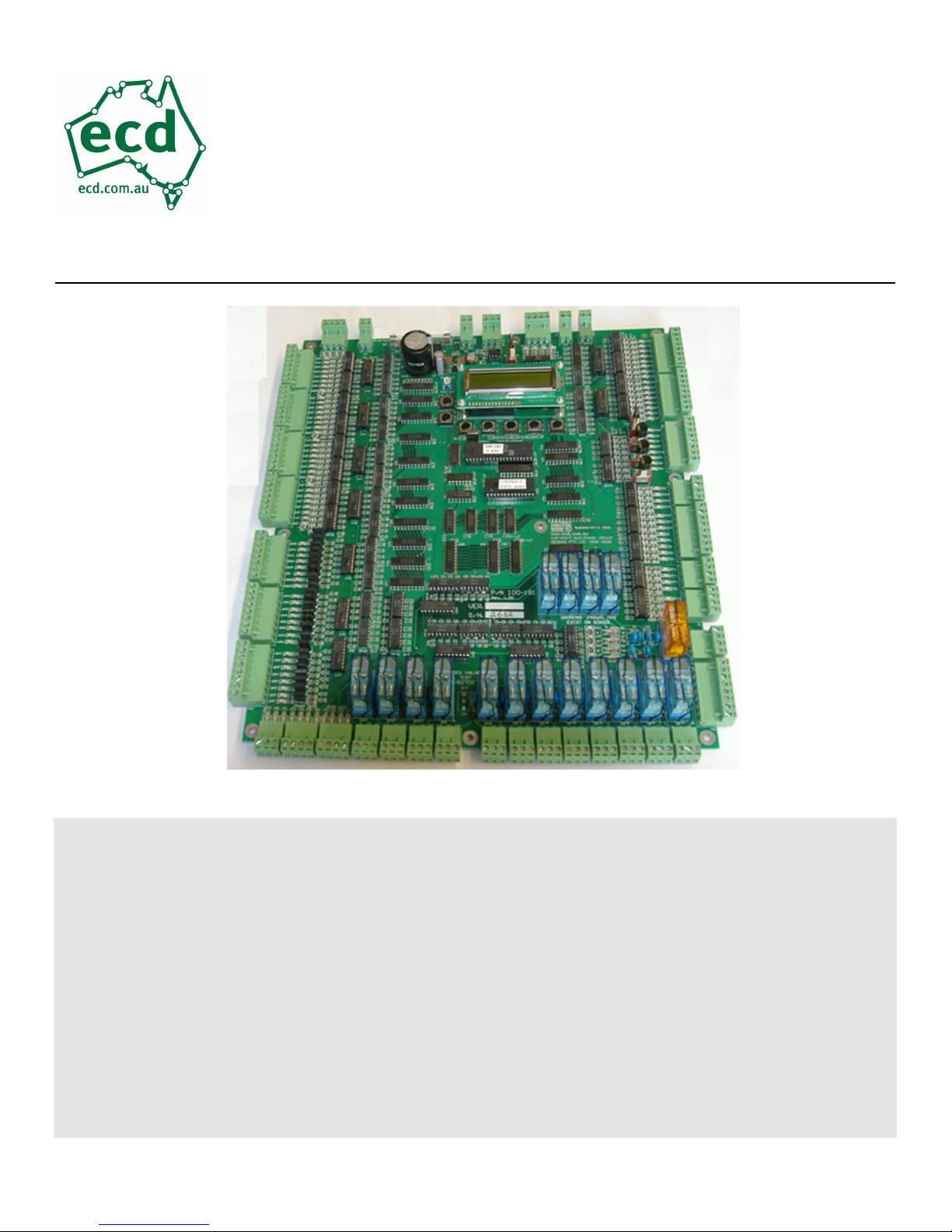
100-181 Controller Manual
Revision Date: Feb 22, 2017
ECD System
Manual
Page 2

E L E C T R O N I C C I R C U I T D E S I G N S P T Y . L T D .
Operation Guide
This manual covers all versions of 100-181 hardware
and software. Some features and operative descriptions
mentioned in this manual may differ or not be available on
earlier 100-181 versions
Electronic Circuit Designs Pty. Ltd.
Factory 11/30 Perry Street • Matraville • NSW • Australia • 2036
Phone 61 2 9316 6909 • Fax 61 2 9316 6797
Email sales@ecd.com.au Web www.ecd.com.au
Page 3

Table of Contents
Table of Contents............................................................................................ i
Section 1: Safety Regulations & Introduction .............................................. 4
1.2.1 Following operating instructions. ............................................ 4
1.2.2 Obligations of operator............................................................. 4
1.2.3 Obligations of personnel........................................................... 4
1.2.4 Hazards associated with the equipment. ................................. 5
1.2.5 Warranty and liability.............................................................. 5
1.2.6 Organizational measures.......................................................... 5
1.2.7 Protective equipment................................................................ 6
1.2.8 Informal safety measures. ........................................................ 6
1.2.9 Training of personnel. .............................................................. 6
1.2.10 Machine controls....................................................................... 6
1.2.11 Safety measures during normal operation.............................. 6
1.2.12 Hazards caused by electric power............................................ 6
1.2.13 Hazards caused by hydraulic power........................................ 7
1.2.14 Special danger areas (examples).............................................. 7
1.2.15 Controller Installation Environmental Requirements.............. 7
1.2.16 Introduction ................................................................................. 8
Section 2: EEProm Settings .......................................................................... 9
EEProm Version 4.02 Summary................................................................. 10
EEProm Definitions (Full description)....................................................... 13
ADO - Advanced Door Opening setup.................................................. 13
ALP – Auxiliary Leveling Pump operation setup ................................ 13
ANS - Anti Nuisance setup..................................................................... 13
BCC - Bottom Car Call setup................................................................ 13
BOT - Bottom floor setup ...................................................................... 13
BST – Brake Switch Time...................................................................... 14
CCMF - Car Call Mask (Front doors) setup........................................ 14
CCMR - Car Call Mask (Rear doors) setup......................................... 14
CNT - CNT Input setup ......................................................................... 14
COD – Parameter lockout function....................................................... 15
DCMF - Down Call Mask (Front doors) setup..................................... 15
DCMR - Down Call Mask (Rear doors) setup...................................... 15
DLI - Door Limit Invert setup............................................................... 15
DLM - Door Limit setup ........................................................................ 16
DRV - Drive type setup .......................................................................... 16
DT - Door Time Close setup .................................................................. 16
DTCF - Door Time Car call (Front doors) close setup ........................ 16
DTCR - Door Time Car call (Rear doors) close setup ......................... 16
DTHF - Door Time Hall call (Front doors) close setup........................ 17
DTHR - Door Time Hall call (Rear doors) close setup ........................ 17
DTL - Door Time Lobby call close setup .............................................. 17
DTRF - Door Time Recall Front setup ................................................. 17
DTRR - Door Time Recall Rear setup .................................................. 17
EQK......................................................................................................... 18
FS - Fire Service type ............................................................................. 18
HFAF - Hall Fire Alternate (Front doors) floor setup .........................18
HFAR - Hall Fire Alternate (Rear doors) floor setup .......................... 18
HFSF - Hall Fire Service (Front doors) return floor setup..................18
HFSR - Hall Fire Service (Rear doors) Return floor setup.................. 19
HRF – Hospital / Hall Recall Front doors............................................. 19
HRR – Hospital / Hall Recall Rear doors.............................................. 19
LCK – Parameter lockout function .......................................................19
LOB - Lobby floor setup ........................................................................ 19
L.# - Lift Number setup..........................................................................19
MOD - MODE Inputs setup...................................................................20
MSL - Magnet Slowing type................................................................... 20
NR - Door Nudging setup ....................................................................... 20
PRK - Park/Zone with doors open......................................................... 20
PRV - Proving required setup................................................................ 20
RLV - Re-Leveling setup ........................................................................ 20
RPT - Run Protection Timer setup ...................................................21
RTM – Run Time short floor run setup ................................................ 21
SDX - Star Delta Exchange Time setup................................................. 21
SDX - VF Drive setting 06,07,08 brake drop time................................ 21
SFR - Short Floor Run setup.................................................................. 21
Spares....................................................................................................... 22
StF - Start Fast ........................................................................................ 22
StM - Start Medium................................................................................22
SlF - Slow Fast......................................................................................... 22
SlM - Slow Medium ................................................................................22
ST2 - Star Delta Changeover Time setup.............................................. 22
ST2 - VF Drive setting 06,07,08 end run time....................................... 22
TCC - Top Car Call setup ...................................................................... 22
TOP - Top floor setup.............................................................................23
UCMF - Up Call Mask (Front doors) setup.......................................... 23
UCMR - Up Call Mask (Rear doors) setup........................................... 23
XTM - Extend run time short floor run ................................................ 23
ZON - Zoning/Parking floor setup......................................................... 23
ZTM - Zoning Time setup...................................................................... 24
#.L - Number of Lifts setup .................................................................... 24
Section 3. Group .......................................................................................... 25
Group Connections and Communication.............................................. 25
Group Checks..........................................................................................26
Group/Duplex Faults ........................................................................... 26
Section 4. Inputs – Outputs.......................................................................... 27
BRK - Brake relay output ......................................................................27
BSL – Bottom SLowing input ................................................................ 27
CBSF - Hall Button Stop (Front doors) output..................................... 27
CBSR - Hall Button Stop (Rear doors) output......................................27
CC - Car Call inputs/Darlington outputs.............................................. 27
CFS - Car Fire Service input.................................................................. 28
Page 4

CFSS - Car Fire Service Start input...................................................... 28
DCBF - Door Close Button (Front doors) input................................... 28
DCBR - Door Close Button (Rear doors) input.................................... 28
DCF - Door Close (Front doors) relay output ...................................... 28
DCR - Door Close (Rear doors) relay output ....................................... 28
DDN - Direction Down output............................................................... 28
DDO - Door Open Disable input / Toggle Switch................................. 28
DF - Down Fast relay output ................................................................. 29
DFCF - Door Fully Closed (Front doors) input.................................... 29
DFCR - Door Fully Closed (Rear doors) input..................................... 29
DFOF - Door Fully Open (Front doors) input...................................... 31
DFOR - Door Fully Open (Rear doors) input....................................... 31
DHC - Down Hall Call inputs/Darlington outputs............................... 32
DN - Down Relay output........................................................................ 33
DOBF - Door Open Button (Front doors) input................................... 33
DOBR - Door Open Button (Rear doors) input.................................... 33
DOF - Door Open (Front doors) relay output...................................... 33
DOR - Door Open (Rear doors) relay output....................................... 33
DS - Down Slow relay output................................................................. 33
DUP - Direction Up output .................................................................... 33
DZ - Door Zone input............................................................................. 33
DZ – Door Zone relay output ................................................................ 33
EDPF - Electronic Door Protection (Front doors) input ..................... 33
EDPR - Electronic Door Protection (Rear doors) input...................... 34
EP - Emergency Power input................................................................. 34
EQK – Earthquake Detection input...................................................... 34
HCB – Hall Call Bypass Input............................................................... 34
HFA - Hall Fire Alternate input............................................................ 34
HFL - Hall Fire Light output................................................................. 34
HFM Hall Fire Machine room/Hoist way input................................... 34
HFR - Hall Fire Reset Input .................................................................. 34
HFS - Hall Fire Service input ................................................................ 35
HFV - Hall Fire Visual signal output .................................................... 35
HV2 - High Voltage input ...................................................................... 35
IDN - Inspection Down input................................................................. 35
IND - Independent Service input........................................................... 35
INSP - Inspection Control input............................................................ 35
IUP - Inspection Up input...................................................................... 35
LEV - Leveling relay output .................................................................. 36
LR – Lock Relay input. ......................................................................... 36
LR – Lock Relay output......................................................................... 36
LRX – Aux LR input.............................................................................. 36
M3 - Door Locks input........................................................................... 36
MSD – Magnetic Switch Down input.................................................... 36
MSU - Magnetic Switch Up input.......................................................... 36
NDGF - Nudging Buzzer output front doors........................................ 37
NDGR - Nudging Buzzer output rear doors......................................... 37
NRF - Nudging output front doors ........................................................37
NRR - Nudging output rear doors......................................................... 37
OS - Out of Service output ..................................................................... 37
PI - Position Indicator output ................................................................ 37
PRK - Parking function input................................................................ 38
PRV - Proving Circuit input .................................................................. 38
PULSE – Pulse Counting input..............................................................38
SAF - Safety Circuit input...................................................................... 38
Sin1 - BKSW - Brake Switch Input .......................................................39
SIn3 – HR Input...................................................................................... 39
SO1 – Inspection Relay Output/Correction Run Output.....................39
SO2 – HR Output....................................................................................39
SP1 - Multi Purpose output 1................................................................. 39
SP2 - Multi Purpose output 2................................................................. 39
SP3 - Multi Purpose Output 3................................................................ 40
SP4 - Multi Purpose output 4................................................................. 40
TSL – Top SLowing input...................................................................... 40
UD - Up/Dn relay output ........................................................................40
UF - Up Fast relay output....................................................................... 40
UHC - Up Hall Call inputs / outputs...................................................... 40
UP - Up relay output...............................................................................40
US - Up Slow relay output......................................................................41
Section 5. Liquid Crystal Display................................................................. 42
LCD Status Line...........................................................................................42
LCD Position & Direction ...................................................................... 42
LCD Modes..............................................................................................42
LCD Lift Status....................................................................................... 43
LCD Door Modes....................................................................................43
LCD Control Buttons .............................................................................44
LCD Display Options.............................................................................. 44
Section 6. Motion ......................................................................................... 46
Motion Control Outputs.........................................................................46
Drive settings and their output status.................................................... 46
Counting Method “00” - Magnet Counting........................................... 54
Counting Method “01” - Pulse Counting. ............................................. 56
Counting Method “02” - Pulse Counting. ............................................. 65
Section 7: Faults – Fault finding................................................................. 67
Upgrade Controller software. ................................................................ 67
Group/Duplex Faults .............................................................................. 67
Leveling inhibit. LEV ............................................................................. 67
Run protection timer. RPT..................................................................... 67
Lift won’t re-level with doors open........................................................ 67
On board fuse blows ............................................................................... 68
Testing 24Vdc.......................................................................................... 68
Doors do not open ................................................................................... 68
Doors close on park................................................................................. 68
Doors don’t open at terminal floors....................................................... 68
Page 5

Lift gets out of step ................................................................................. 68
Lift does not answer car calls................................................................. 68
Lift does not answer hall calls................................................................ 68
Lift misses hall calls................................................................................ 68
Re-leveling won’t operate....................................................................... 69
Red3 LED is not blinking....................................................................... 69
Processor errors/Lockup: ...................................................................... 69
Section 8. Upgrades, Changes & Technical Information........................... 70
Controller ID. .............................................................................................. 71
Terminal Screw Torque Settings................................................................. 72
Page 6

S A F E T Y R E G U L A T I O N S & I N T R O D U C T I O N
Section
1
Section 1: Safety Regulations & Introduction
Section 1.1 Safety Regulations
Elevator controllers and other electrical components can cause serious harm or death if installation guides are not
met. It is the responsibility of the installer of our equipment to ensure that once installed, the equipment does not
pose any threat, danger or hazard.
Installation of this equipment shall be done in accordance with AS1735 for Australia and with all applicable local
codes and NFPA 70 (National Electric Code) for the U.S.A. and C22.1-02 Canadian Electrical Code Part 1 for
Canada as well as ASME A17.1, CAN/CSA-B44.1.
Section 1.2 Obligations and Liability
1.2.1 Following operating instructions.
• In order to ensure safe handling and problem free operation of this equipment, it is absolutely
essential for the relevant personal to be fully acquainted with the relevant safety regulations.
• These operating instructions contain the most important information for operating the machine correctly
and safely.
• These operating instructions, in particular the safety regulations, must be observed by all those persons
who work on the equipment.
• Furthermore, all locally applicable rules and regulations relating to accident prevention and installation
must be observed.
1.2.2 Obligations of operator.
The operator undertakes to allow only those persons to work on the equipment who
• Are fully acquainted with the basic regulations relating to safety in the workplace and accident prevention
and to have been trained in handling the equipment.
• Have read the safety regulations and the warning notices contained in these the operating instructions.
• Regular checks are conducted to ensure that personnel perform their duties with safety considerations
foremost in their minds.
1.2.3 Obligations of personnel.
All personnel charged with working on the machine undertake prior to starting work to
• Observe the basic regulations relating to safety in the workplace and accident prevention.
• Read the operating instructions, in particular the safety regulations, and confirm by way of their signature
that they have understood them.
Page 7
S A F E T Y R E G U L A T I O N S & I N T R O D U C T I O N
1.2.4 Hazards associated with the equipment.
The equipment is built with state-of-the-art technology and recognized safety regulations. Nevertheless, use of the
equipment can result in dangers to life and limb for the installer, user or a third party and in impairments to the
equipment or to other material property. The equipment must only be used
• For its intended purpose.
• In perfect condition in terms of safety requirements.
Operate the equipment in technically perfect condition and for its intended use only while bearing in mind all
safety and hazard considerations and following the operating instructions. In particular, faults which restrict safety
must be rectified immediately after they have been identified and at the latest before the equipment is started up.
Compliance Testing for AS/NZS CISPR 22:2002 Class A
WARNING !
This is a Class A product. In a domestic environment this product may cause radio
interference in which case the user may be required to take adequate measures.
Compliance Testing for FCC Title 47 Part 15, Subpart B Class A
FCC PART 15
This device complies with part 15 of the FCC rules. Operation is subject to the
following two conditions:
1. This device may not cause harmful interference, and
2. This device must accept any interference received, including interference that
may cause undesired operation.
1.2.5 Warranty and liability.
Our “Sales terms and conditions” apply. These terms and conditions will have been available to the purchaser at
time of sale. Warranty and liability shall be limited to repairs and replacement to the equipment purchased from
us. Warranty and liability claims shall not be entertained if they can be traced back to one or more of the following
causes.
• Equipment not used for its intended purpose.
• Improper installation, startup, operation and maintenance of the equipment.
• Operation of the equipment with faulty safety devices or improperly installed or non-operational safety
and protective equipment.
• Failure to observe the information, instructions and notices contained in the operating instructions
relating to transportation, storage, installation, startup, operation, maintenance and setting up of the
equipment.
• Inadequate monitoring of the equipment parts which are subject to wear.
• Improperly conducted repairs.
• Catastrophes caused by the influence of foreign bodies and force majeure.
1.2.6 Organizational measures.
• The installer and or maintainer shall provide the necessary protective equipment for the personnel
• All existing safety equipment must be checked at regular intervals.
Page 8

S A F E T Y R E G U L A T I O N S & I N T R O D U C T I O N
1.2.7 Protective equipment.
• At all times, prior to putting the machine into operation, all protective equipment must be correctly
installed and in proper working condition.
• Protective equipment may only be removed
- after the machine has come to a complete stop and the machine has been disabled to ensure it
cannot be started up again.
- if subcomponents are delivered, the operator must install the protective equipment in
accordance with regulations
1.2.8 Informal safety measures.
• Keep the operating instructions and circuit diagrams permanently at the site where the equipment is
installed.
• In addition to the operating instructions, the generally valid and local regulations relating to accident
prevention and environmental protection must be provided and observed.
• Maintain all safety and danger notices on/next to the machine in legible condition and comply with
them.
• If the equipment is sold or transferred, the operating instructions must be included with the equipment.
1.2.9 Training of personnel.
• Only personnel who have been trained and instructed are allowed to work on the machine.
• The responsibilities of the personnel must be clearly defined for the machine/controller installation,
startup, operation, setting-up, maintenance and repairs.
• Personnel still in the process of being trained are only permitted to work at the machine under the
supervision of an experienced person.
1.2.10 Machine controls.
• Under no circumstances carry out any program modifications to the software!
• Only properly instructed personnel are permitted to operate the controls.
• The machine must not be operated if potential electromagnetic interference sources are acting on the
machine. Interference sources are e.g. welding equipment, portable phones.
1.2.11 Safety measures during normal operation.
• Only operate the machine when all protective equipment is fully operational.
• Prior to switching on the machine, ensure that the startup can cause no harm to personnel.
• Regularly maintain and check machine for externally identifiable damage and check that all the safety
devices are operational.
1.2.12 Hazards caused by electric power.
• Ensure 0V and +24V are free from other voltages. High voltages may be superimposed on 0V
and 24Vdc lines as no reference to ground exists. See Warning 1.2.14
• Work on the electric power supply may only be carried out by a qualified electrician.
• Check the electrical equipment of the machine at regular intervals.
Repair loose connections and scorched cables immediately.
• Keep the control cabinet locked at all times. Access is only permitted to authorized personnel with a key
or tool.
Page 9

S A F E T Y R E G U L A T I O N S & I N T R O D U C T I O N
• If work has to be carried out on live parts, do this only in the presence of a second person who can
switch off the master switch in an emergency.
• The machine causes electromagnetic interference sources. For this reason, do not use any sensitive
equipment in its vicinity.
• For EMC reasons, the controller must not be modified.
1.2.13 Hazards caused by hydraulic power.
• Only personnel with special knowledge and experience in the field of hydraulics may work on hydraulic
equipment.
• Before beginning repairs, depressurize system sections and pressure lines which are to be opened.
1.2.14 Special danger areas (examples).
• When on inspection, always ensure either of the common or direction control buttons stops the lift.
• The common button shall break the safety line and the 0V up/down direction input.
• Never place yourself or any party in a position of danger where relying on any single safety measure.
• Automatic machines start without warning. Care must be taken at all times.
WARNING !
Always treat terminals and conductors as dangerous. High voltages may be
superimposed on 0V and 24Vdc lines as no reference to ground exists. Always
meter these points to ensure correct voltage exists.
1.2.15 Controller Installation Environmental Requirements
Controller cabinet must be installed in a location free from;
• Dust and dirt.
• Excessive heat and humidity. Ambient temperature should not exceed 40°C /104°F.
• Excessive vibrations.
• Mist or water
When mounting controller cabinet, ensure it is suitably supported.
Page 10

E E P R O M S E T T I N G S
T
1.2.16
he 100-181 controller enables independent control of the front and rear doors at each
floor.
The 100-181 controller can operate up to 8 floors.
The controllers can be grouped up to a 6 car group and may be inter-connected using 3 wire serial communication. A
separate group controller is therefore, not required.
Processor
Under normal operation;
When re-powering; ensure the lift is off for 10 seconds before turning back on.
On power up, a delay of approximately 2 seconds is given on start up to ensure voltages are stable prior to reading
and writing outputs.
Introduction
• The red Red3 LED blinks to confirm that the microprocessor is running.
• The yellow Yel3 LED comes on to confirm outputs are enabled.
• The green Grn3 LED comes on during power up and turns off during normal operation. It will
also flash once when a new value has been written in to EEPROM.
Page 11
E E P R O M S E T T I N G S
Section
2
Section 2: EEProm Settings
EEProm How to read and modify settings
This EEProm holds settings for the particular contract data including number of
floors, door type and drive types.
The EEPRom holds values for various contract settings which may be altered on site. Each setting has a definition
followed by its value in hex followed by its value in bit format.
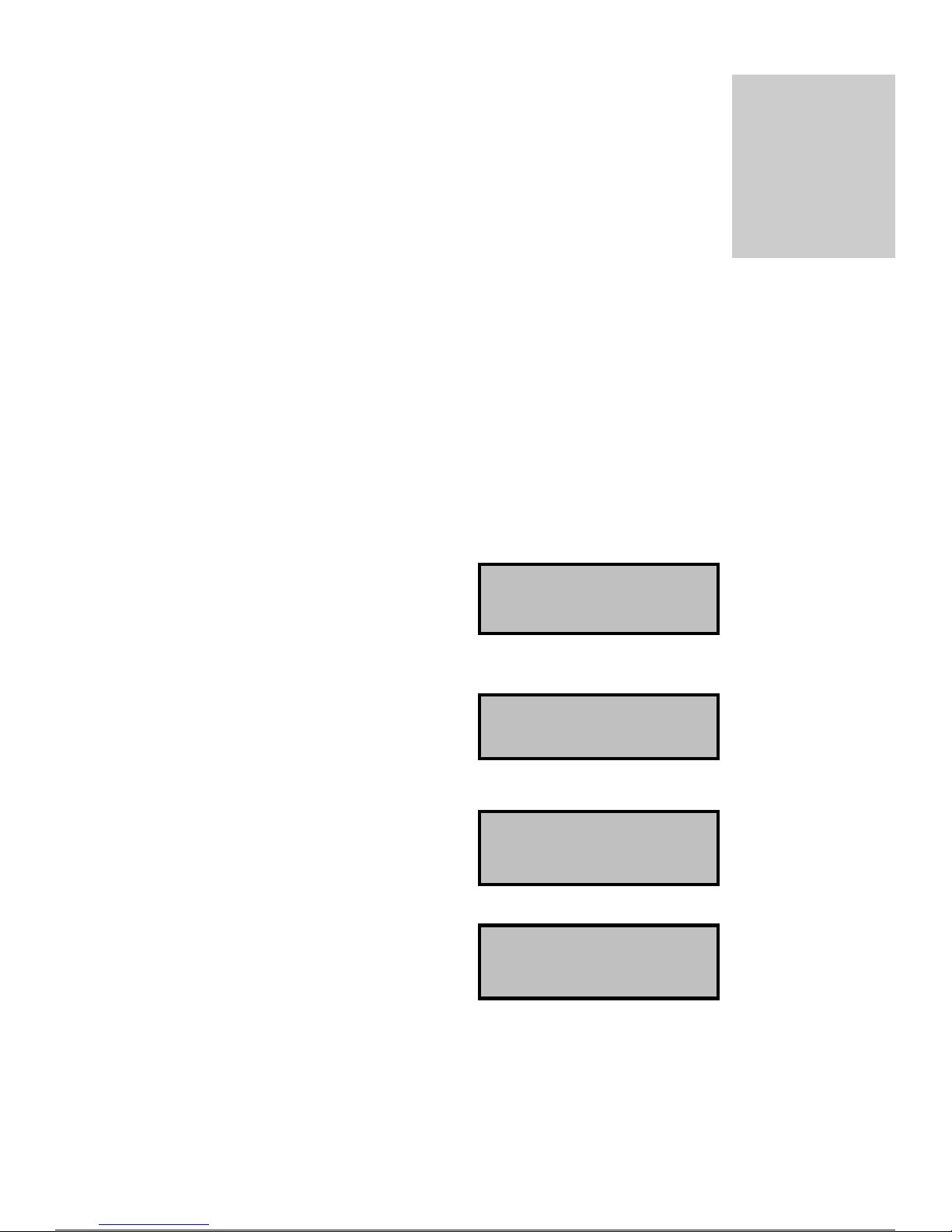
To inspect the settings from the power up state,
press the forward “>” button located to the left
below the LCD until the EEPROM setting appears.
To inspect the settings from the power up state,
press the forward “>” button located to the left
below the LCD until the EEPROM setting appears.
Now you can use the up “∧” and down “∨”buttons
to scroll through the settings. If you want to change
a setting press the enter “ENT” button and a * shall
appear on the screen to indicate you are in edit mode.
Now use the up “∧” and down “∨” buttons to
change the setting. When you are at the required
value press the enter “ENT” button again and the *
shall disappear.
EEProm Security
A special write sequence has been added to ensure unauthorized writes to the EEProm are not made. Only
operates with EEProms with this capability. These EEproms are recommended and identified by a “contract data
secure” label.
01- NOR IDL ][
ECD Aust. V-4.02
01- NOR IDL ][
TOP: 08:00001000
01- NOR IDL ][
TOP:*08:00000010
01- NOR IDL ][
TOP: 06:00000010
Page 12

E E P R O M S E T T I N G S
EEProm Version 4.02 Summary
The EEProm holds values for various contract settings which may be altered on site. Each setting has a definition
followed by its value in hex and then its value in bit format.
Note: Refer to EEProm Definitions (Full description) for more information.
BOT Bottom floor number (VALUE)
Setting example:- BOT 01: 00000001 (Level 1)
TOP Top floor number (VALUE)
Setting example:- TOP 06: 00000110 (Level 6 is top floor)
BCC Bottom car call for “BOT CALL” button on the circuit board (MASK)
Setting example:- BCC 80: 10000000 (Bottom call Level 1)
TCC Top car call for “TOP CALL” button on the circuit board (MASK)
Setting example:-TCC 04: 00000100 (Top call to level 6)
CCMF Car call mask. Front doors floors allowed. (MASK)
Setting example:-CCMF FC: 11111100 (Front doors, levels 1-6)
CCMR Car call mask. Rear doors floors allowed. (MASK)
Setting example:-CCMR F8: 11111000 (Rear doors, levels 1-5)
UCMF Up call mask. Front doors floors allowed. (MASK)
Setting example:- UCMF F8: 11111000 (Front doors, levels 1U-5U)
UCMR Up call mask. Rear doors floors allowed. (MASK)
Setting example:- UCMR F0: 11110000 (Rear doors, levels 1U-4U)
DCMF Down call mask. Front doors floors allowed. (MASK)
Setting example:- DCMF 7C: 01111100 (Front doors, levels 2D-6D)
DCMR Down call mask. Rear doors floors allowed. (MASK)
Setting example:- DCMR 78: 01111000 (Rear doors, levels 2D-5D)
LOB Lobby floor. (MASK)
Setting example:- LOB 40: 01000000 (Level 2 is the master zoning floor)
ZON Zone floor. (MASK)
Setting example:-ZON 10: 00010000 (Zone to Level 4)
ZTM Zoning time. (VALUE)
Setting example:-ZTM 06: 00000110 (= 60seconds)
HFSF Hall fire service floor. Front doors floors (MASK)
Setting example:-HFSF 80: 10000000 (Front doors, level 1)
HFSR Hall fire service floor. Rear doors floors (MASK)
Setting example:-HFSR 00: 00000000 (Rear doors, no setting)
SFR Short Floor Run (MASK)
Setting example:- SFR 9F: 10011111 (Short floor between 2&3)
L.# Lift Number (VALUE)
Setting example:- L.# 02: 00000010 (Lift #2)
#.L Number of Lifts (VALUE)
Setting example:- #.L 03: 00000011 (3 Lifts in group)
MOD Mode inputs (MASK)
Setting example:- MOD 02: 00000010 (CFS input inverted)
CNT CNT inputs (MASK)
Setting example:- CNT 02: 00000010 (DOB input inverted)
HFAF Hall fire alternate floor. Front doors floors. US only (MASK)
Setting example:- HFAF 00: 00000000 (Front doors, no setting)
HFAR Hall fire alternate floor. Rear doors floors. US only (MASK)
Setting example:- HFAR 40: 01000000 (Rear doors, level 2 alt. fire floor)
PRV If set to "1" requires PRV on all DRV settings
Page 13

E E P R O M S E T T I N G S
RPT Run protection timer
Setting example:-RPT 01: 00000001 (25s)
DRV Drive control type.
Setting example:-DRV 02: 00000010 (3010/2CH/S block)
ST2 Star Delta time. (VALUE)
Setting example:-ST2 08: 00001000 (= 800ms)
SDX Star Delta Exchange time. (VALUE)
Setting example:-SDX 01: 00000001 (= 100ms)
MSL Magnet slowing type.
Setting example:- MSL 00: 00000000 (MSU/MSD slowing)
MSL 01: 00000001 (Pulse slowing)
RTM Extend run time. – If slowing is obtained less than this time, then add the value
of in XTM on before dropping high speed.
Setting example:-RTM 00: 00000000 (No extended run time.)
XTM Extend run time. – If a short floor determined by RTM then add this amount of
Time on before dropping high speed.
Setting example:-XTM 00: 00000000 (No extended run time.)
StF Start Fast. - Number of pulses it takes to reach fast speed.
StM Start Medium.- Number of pulses it takes to reach medium speed.
SlF Slow Fast. - Number of pulses it takes to slow from fast speed.
SlM Slow Medium.- Number of pulses it takes to slow from medium speed.
RLV Re-leveling. Turn re-leveling on/off.
Setting example:-RLV 00: 00000000 (No Re-level.)
RLV 01: 00000001 (Re-leveling on.)
DLM Door limit mask.
Setting example:-DLM 00: 00000000 (Single doors.)
DLM 01: 00000001 (Multi doors.)
DLM 02: 00000010 (Door cam.)
DLI Door limit invert. (MASK)
Setting example:-DLI 00: 00000000 (Limits not inverted.)
NR Nudging Relay for door nudging/Passing tone (MASK)
Setting example:-NR 00: 00000000 (Nudging off.)
ADO Advanced Door Opening.
Setting example:-ADO 00: 00000000 (Off )
DTCF Door time car call for front doors. (VALUE)
Setting example:-DTCF 32: 00110010 (= 5000ms, “5 seconds”)
DTCR Door time car call for rear doors. (VALUE)
Setting example:-DTCR 32: 00110010 (= 5000ms, “5 seconds”)
DTHF Door time hall call for front hall. (VALUE)
Setting example:-DTHF 32: 00110010 (= 5000ms, “5 seconds”)
DTHR Door time hall call for rear hall. (VALUE)
Setting example:-DTHR 32: 00110010 (= 5000ms, “5 seconds”)
DTL Door time lobby. (VALUE)
Setting example:-DTL 32: 00110010 (= 5000ms, “5 seconds”)
ANS Anti Nuisance EDP. (VALUE)
Set to the number of times a car call is answered without EDP activation before calls are cancelled.
PRK Park/Zone with doors closed/open. Set to 00 – doors closed.
FS Fire service type
Setting example:-FS 00: 00000000 (Australian fire service.)
FS 01: 00000001 (Code 17.1 U.S.A..)
DT Door Time Close Setup. Door Time Canceling Function
Setting example:-DT 01: 00000001 (Door Timing Canceling Activated)
BST Brake Switch Time
Setting example:-BST 03: 00000011 (3s)
Page 14

E E P R O M S E T T I N G S
DTRF Door time HR recall . (VALUE)
Setting example:-DTRF 32: 00110010 (= 5000ms, “5 seconds”)
DTRR Door time HRR recall . (VALUE)
Setting example:-DTRR 32: 00110010 (= 5000ms, “5 seconds”)
HRF Hosp / Hall recall mask.
Setting example:-HRF 40: 01000000
HRR Hosp / Hall recall mask.
Setting example:-HRR 40: 01000000
ALP Auxiliary Leveling Pump. Turns on Auxiliary Leveling Pump, for Up Re Level operation.
Setting example:- ALP FF:11111111 (No Auxiliary pump Re-level.)
ALP 01: 00000001 (Re-leveling with Auxiliary pump)
LCK EEProm Lock (Unlock default 67)
COD Lock code (Unlock default 89)
EQK N/A. Do not adjust
Page 15

E E P R O M S E T T I N G S
EEProm Definitions (Full description)
ADO - Advanced Door Opening setup
Sets the doors to open whilst traveling into the floor. The doors shall commence opening when the lift is within the
door zone and the MSU or MSD vane pending direction.
ADO EEPROM Advanced Door Opening.
00: 00000000 “Off – Default”
01: 00000001 ”On”
ALP – Auxiliary Leveling Pump operation setup
For hydraulic lifts, ALP can be set to control SP3 relay to allow Up Re-Leveling using the Auxiliary Pump motor.
For “SP3” relay to energise when performing an Up Re level set ALP to “01” and DRV to “00”, “02” or “05”.
The contacts of SP3 may also be used to stop a secondary pump starting when Up Re-Leveling
If ALP is set to “01”, SP3 shall NOT turn on for inspection.
ALP EEPROM Auxiliary Leveling Pump.
FF: 11111111 “Off”
01: 00000001 “On – operates SP3 for Up Re-Level or inspection”
ANS - Anti Nuisance setup
Set to the number of times a car call is answered without EDP (Electronic Doors Protection) activation before calls
are cancelled. Counter is reset to zero if either EDPF or EDPR is activated. If a hall call is present as well as a car
call, the counter will not increment.
ANS EEPROM Anti Nuisance.
00: 00000000 “Off”
03: 00000011 ”On – operates after 3 car calls of no EDP in a row.”
1e: 00011110 ”On – operates after 30 car calls of no EDP in a row - Default”
BCC - Bottom Car Call setup
BCC EEPROM Bottom car call for the “BOT CALL” button on the circuit board (MASK)
First floor served for this lift only.
The controller shall enter a car call to this setting when the “BOT CALL’ button on the circuit board is pressed.
80: 10000000 (Level 1)
40: 01000000 (Level 2)
20: 00100000 (Level 3)
10: 00010000 (Level 4)
08: 00001000 (Level 5)
BOT - Bottom floor setup
BOT EEPROM Bottom number (VALUE)
Set value to lowest floor served. (01 to 05 valid values)
Lift resets to “BOT” value when BSL limit is activated.
Page 16

E E P R O M S E T T I N G S
This signal can be used when a lift in the group doesn’t go all the way to the bottom.
01: 00000001 (Level 1)
02: 00000010 (Level 2)
03: 00000011 (Level 3)
04: 00000100 (Level 4)
05: 00000101 (Level 5)
BST – Brake Switch Time
For brake switch monitoring.
BST sets the time that the BKSW input must be turned on (to prove the brake has lifted) once the brake lift
command (BRK relay pulled in) has been initiated.
Setting example:
01: 00000001 = 1s
02: 00000010 = 2s
03: 00000011 = 3s
04: 00000100 = 4s
05: 00000101 = 5s
FF: 11111111 = OFF. BKSW not monitored.
Any other setting than 01-05 will turn the brake switch monitoring OFF.
BST is a fatal error. Reset is only via a processor POR.
See also Input - Output, Sin1- BKSW.
CCMF - Car Call Mask (Front doors) setup
CCMF EEPROM Car call mask. Front doors floors allowed. (MASK). For this lift only.
This setting lets you define the floors which the lift serves via the front doors.
Set bits to a “1” car call allowed or a “0” for not allowed.
C0: 11000000 (1c,2c)
E0: 11100000 (1c,2c,3c)
F0: 11110000 (1c,2c,3c,4c)
F8: 11111000 (1c,2c,3c,4c,5c)
FC: 11111100 (1c,2c,3c,4c,5c,6c)
Note: This masking feature shall not to be used as a means providing of floor security, as it shall disable the car
calls in Fire Service and other modes of operation.
CCMR - Car Call Mask (Rear doors) setup
CCMR EEPROM Car call mask. Rear doors floors allowed. (MASK). For this lift only.
This setting lets you define the floors which the lift serves via the rear doors.
Set bits to a “1” car call allowed or a “0” for not allowed.
C0: 11000000 (1c,2c)
E0: 11100000 (1c,2c,3c)
F0: 11110000 (1c,2c,3c,4c)
F8: 11111000 (1c,2c,3c,4c,5c)
FC: 11111100 (1c,2c,3c,4c,5c,6c)
Note: This masking feature shall not to be used as a means providing of floor security, as it shall disable the car
calls in Fire Service and other modes of operation.
CNT - CNT Input setup
Enables the following CNT inputs to be inverted; DCBF, DOBF, EDPF, DCBR, DOBR, EDPR.
CNT EEPROM (MASK)
00: 00000000 No inputs inverted.
01: 00000001 DCBF. Door close front input inverted
02: 00000010 DOBF. Door open front input inverted
04: 00000100 EDPF. Light ray front input inverted
Page 17

E E P R O M S E T T I N G S
08: 00001000 Not used. Default to 0.
10: 00010000 Not used. Default to 0.
20: 00100000 DCBR. Door close rear input inverted
40: 01000000 DOBR. Door open rear input inverted
80: 10000000 EDPR. Light ray rear input inverted
eg. 42: 01000010 = Both DOBF and DOBR door open button inputs inverted.
COD – Parameter lockout function
To stop unauthorised adjustments to the EEprom parameters the COD and LCK parameters are used.
COD and LCK must both be set to default values to allow other parameters to be adjusted.
See also Eeprom setting LCK
COD default. 89: 10001001
LCK default. 67: 01100111
DCMF - Down Call Mask (Front doors) setup
DCMF EEPROM (MASK) Front doors down hall calls allowed for this lift only.
This setting lets you define the DOWN front doors floors which the lift can serve via DOWN HALL CALLS
Set bits to a “1” hall call allowed or a “0” for not allowed.
40: 01000000 (2d)
60: 01100000 (2d,3d)
70: 01110000 (2d,3d,4d)
78: 01111000 (2d,3d,4d,5d)
7C: 01111100 (2d,3d,4d,5d,6d)
DCMR - Down Call Mask (Rear doors) setup
DCMR EEPROM (MASK) Rear doors down hall calls allowed for this lift only.
This setting lets you define the DOWN rear doors floors which the lift can serve via DOWN HALL CALLS
Set bits to a “1” hall call allowed or a “0” for not allowed.
40: 01000000 (2d)
60: 01100000 (2d,3d)
70: 01110000 (2d,3d,4d)
78: 01111000 (2d,3d,4d,5d)
7C: 01111100 (2d,3d,4d,5d,6d)
DLI - Door Limit Invert setup
DLI is only valid when DLM is set to 00, 03 or 04. See also EEprom setting DLM.
DLI setting is used to invert the DFOF/DFOR and DFCF/DFCR inputs when normally open (n/o) door limit
contacts are used.
DLI EEPROM Door limit invert. (MASK)
DLI: 00 “Limits not inverted.”
DLI: 01 “ Limits inverted.” Any setting other than 00 shall default to inverted limits.
DLI set to 00 - Limits not inverted. Using n/c limits.
Doors fully open – DFCF/DFCR LED will be on. DFOF/DFOR LED will be off
Doors fully closed – DFCF/DFCR LED will be off. DFOF/DFOR LED will be on
Doors midway – DFCF/DFCR LED will be on. DFOF/DFOR LED will be on
DLI set to 01 - Limits inverted. Using n/o limits.
Doors fully open – DFCF/DFCR LED will be off. DFOF/DFOR LED will be on
Doors fully closed – DFCF/DFCR LED will be on. DFOF/DFOR LED will be off
Page 18

E E P R O M S E T T I N G S
Doors midway – DFCF/DFCR LED will be off. DFOF/DFOR LED will be off
DLM - Door Limit setup
This signal sets up the door limits inputs.
See also EEprom setting DLI, DFCF/DFCR, DFOF/DFOR.
DLM EEPROM Door limit mask.
Setting example:
DLM 00: 00000000 (Door open and close limits going to DFOF/DFOR, DFCF/DFCR
inputs which drop DOF/DOR and DCF/DCR relays).
DLM 01: 00000001 N/A
DLM 02: 00000010 (Door cam control) DC relay output used to control Cam operation.
Nb: 1 sec delay from DO picking up after DC has dropped. (to allow time for cam
to drop and locks to break, to avoid lock “snagging”).
See also Input - Output, DFCF/R.
DLM 03: 00000011 (As per setting “00” but DOF/DOR and DCF/DCR relays are held up)
DLM 04: 00000100 (As per setting “00” but DCF/DCR relay picks up whilst running).
DRV - Drive type setup
This sets the drive output type. Relay output configurations are changed to suit equipment installed.
Refer to operation section for motion outputs.
DRV…EEPROM…Drive control type.
00: 00000000 “Standard hyd. block valve. 3010EN”
01: 00000001 ”DA DynaHyd valve.”
02: 00000010 “Soft valve. 3010/2CH/S”
03: 00000011 “VF type 1; Keb VF drive, Zetadyn VF drive”
04: 00000100 “1,2 speed AC”
05: 00000101 “GMV 3010/S, Blain EV100”, Maxton, Bucher LRV, EECO
06: 00000110 “VF type 2”
07: 00000111 “VF type 3; ABB VF drive”
DT - Door Time Close setup
This setting allows the door fully open time NOT to be canceled when a car-call or door closed button
(DCBF/DCBR) is pressed.
Setting example:
DT 00: 00000000 (NOT ALLOW pressing a car-call or door close button to cancel door timing).
DT 01: 00000001 (ALLOW pressing a car-call or door close button to cancel door timing).
DTCF - Door Time Car call (Front doors) close setup
Sets the amount of time before the front doors close for a car call whilst on normal operation.
DTCF EEPROM Front doors time close. (VALUE)
Set value for front door close time.
The time is set in 100ms increments.
1e: 00011110 = 3000ms, “3 seconds”
32: 00110010 = 5000ms, “5 seconds”
90: 10010000 = 14400ms, “14.4 seconds”
(01 to FF valid values.)
DTCR - Door Time Car call (Rear doors) close setup
Sets the amount of time before the rear doors close for a car call whilst on normal operation.
DTCR EEPROM Rear door time close. (VALUE)
Set value for rear door close time.
The time is set in 100ms increments.
1e: 00011110 = 3000ms, “3 seconds”
Page 19

E E P R O M S E T T I N G S
32: 00110010 = 5000ms, “5 seconds”
90: 10010000 = 14400ms, “14.4 seconds”
(01 to FF valid values.)
DTHF - Door Time Hall call (Front doors) close setup
Sets the amount of time before the front doors close for a hall call whilst on normal operation.
Lobby time (DTL) overrides this setting when lift is at the lobby floor.
Recommend DTHF is set equal to or greater than DTCF.
DTHF EEPROM Front door hall call time close. (VALUE)
Set value for front door close time.
The time is set in 100ms increments.
1e: 00011110 = 3000ms, “3 seconds”
32: 00110010 = 5000ms, “5 seconds”
90: 10010000 = 14400ms, “14.4 seconds”
(01 to FF valid values.)
DTHR - Door Time Hall call (Rear doors) close setup
Sets the amount of time before the rear doors close for a hall call whilst on normal operation.
Lobby time (DTL) overrides this setting when lift is at the lobby floor.
Recommend DTHR is set equal to or greater than DTCR.
DTHR EEPROM Rear door hall call time close. (VALUE)
Set value for rear door close time.
The time is set in 100ms increments.
1e: 00011110 = 3000ms, “3 seconds”
32: 00110010 = 5000ms, “5 seconds”
90: 10010000 = 14400ms, “14.4 seconds”
(01 to FF valid values.)
DTL - Door Time Lobby call close setup
Sets the amount of time before the doors close after a lobby call is answered when on normal operation.
DTL value overrides DTHF/DTHR value when answering a hall call at the lobby floor.
Recommend DTL is set equal to or greater than DTHF/DTHR and DTCF/DTCR.
DTL EEPROM Door time close. (VALUE)
Set value for door close time.
The time is set in 100ms increments.
1e: 00011110 = 3000ms, “3 seconds”
32: 00110010 = 5000ms, “5 seconds”
90: 10010000 = 14400ms, “14.4 seconds”
(01 to FF valid values.)
DTRF - Door Time Recall Front setup
Sets the amount of time before the front doors close after returning to HR or HR1 floor and lift not being
switched to IND or CFS.
The time is set in 100ms increments.
Eg. 32: 00110010 = 5000ms, “5 seconds”
See also Inputs-Outputs SIN3
DTRR - Door Time Recall Rear setup
Sets the amount of time before the rear doors close after returning to HR or HR1 floor and lift not being switched
to IND or CFS.
The time is set in 100ms increments.
Eg. 32: 00110010 = 5000ms, “5 seconds”
See also Inputs-Outputs SIN3
Page 20

E E P R O M S E T T I N G S
EQK
N/A. Do not adjust.
FS - Fire Service type
Australia: Set to 00: 00000000
USA Only. Fire Service Code 17.1. FS EEprom setting must be set to 01: 00000001
HFAF - Hall Fire Alternate (Front doors) floor setup
USA Only. Fire Service Code 17.1. FS EEprom setting must be set to 01
When the designated floor smoke alarm is activated, the lift shall return to the HFAF floor if there is a setting floor.
See also Inputs-Outputs HFAF
HFAF…EEPROM Hall Fire Alternate (Front doors) floor. (MASK)
00: 00000000 (No setting floor)
80: 10000000 (Level 1)
40: 01000000 (Level 2)
20: 00100000 (Level 3)
10: 00010000 (Level 4)
08: 00001000 (Level 5)
04: 00000100 (Level 6)
Note: Set either HFAF OR HFAR. DO NOT set both of them.
HFAR - Hall Fire Alternate (Rear doors) floor setup
USA Only. Fire Service Code 17.1. FS EEprom setting must be set to 01
When the designated floor smoke alarm is activated, the lift shall return to the HFAR floor if there is a setting
floor.
See also Inputs-Outputs HFAR
HFAR…EEPROM Hall Fire Alternate (Rear doors) floor. (MASK)
00: 00000000 (No setting floor)
80: 10000000 (Level 1)
40: 01000000 (Level 2)
20: 00100000 (Level 3)
10: 00010000 (Level 4)
08: 00001000 (Level 5)
04: 00000100 (Level 6)
Note: Set either HFAF OR HFAR. DO NOT set both of them.
HFSF - Hall Fire Service (Front doors) return floor setup
This sets the hall fire service return front doors floor activated when HFS input is active whilst in normal mode and
HFSF has a setting floor.
HFSF…EEPROM Hall Fire Service (Front doors) floor. (MASK)
00: 00000000 (No setting floor)
80: 10000000 (Level 1)
40: 01000000 (Level 2)
20: 00100000 (Level 3)
10: 00010000 (Level 4)
08: 00001000 (Level 5)
04: 00000100 (Level 6)
Note: Set either HFSF OR HFSR. DO NOT set both of them.
Page 21

E E P R O M S E T T I N G S
HFSR - Hall Fire Service (Rear doors) Return floor setup
This sets the hall fire service return rear doors floor activated when HFS input is active whilst in normal mode and
HFSR has a setting floor.
HFSR…EEPROM Hall Fire Service (Rear doors) floor. (MASK)
00: 00000000 (No setting floor)
80: 10000000 (Level 1)
40: 01000000 (Level 2)
20: 00100000 (Level 3)
10: 00010000 (Level 4)
08: 00001000 (Level 5)
04: 00000100 (Level 6)
Note: Set either HFSF OR HFSR. DO NOT set both of them.
HRF – Hospital / Hall Recall Front doors
This sets the Hospital Recall floor for the front doors when lift is in HR mode.
See also Inputs-Outputs SIN3 and Eeprom settings HRR
If HRF is set, HRR MUST be 00 or recall shall not operate.
eg. 40: 01000000 (Level 2)
HRR – Hospital / Hall Recall Rear doors
This sets the Hospital Recall floor for the rear doors when lift is in HR mode.
See also Inputs-Outputs SIN3 and Eeprom settings HRF
If HRR is set, HRF MUST be 00 or recall shall not operate.
eg. 20: 00100000 (Level 3)
LCK – Parameter lockout function
To stop unauthorised adjustments to the EEprom parameters the LCK and COD parameters are used.
LCK and COD must both be set to default values to allow other parameters to be adjusted.
See also Eeprom setting COD
LCK default. 67: 01100111
COD default. 89: 10001001
LOB - Lobby floor setup
This signal sets the master zoning floor. After the zone time period as defined by ZTM, a lift shall zone to floor
defined by LOB, if unoccupied. If LOB floor is occupied then the lift shall alternatively zone to ZON floor.
A lift shall zone to floor defined by LOB and ignore ZON, when working in simplex.
LOB EEPROM Lobby floor. (MASK) Master zoning floor.
LOB must be set to the same value in all lifts belong to the group.
00: 00000000 (No zoning). To disable zoning set “LOB” and “ZON” to “00”.
80: 10000000 (Level 1)
40: 01000000 (Level 2)
20: 00100000 (Level 3)
10: 00010000 (Level 4)
08: 00001000 (Level 5)
04: 00000100 (Level 6)
L.# - Lift Number setup
Lift number setup.
Example: In a 2 car group you must have one lift set to 01 and the other set to 02. It doesn’t matter which way
around they are as long as each lift is different.
Page 22

E E P R O M S E T T I N G S
L.#…EEPROM…Lift # (VALUE). Set value to lift number. (01 to 06 valid values.)
01: 00000001 (Lift 1)
02: 00000010 (Lift 2)
03: 00000011 (Lift 3)
04: 00000100 (Lift 4)
05: 00000101 (Lift 5)
06: 00000110 (Lift 6)
MOD - MODE Inputs setup
Enables the 3 MODE inputs to be inverted. CFS, HFS, IND
MOD EEPROM (MASK)
08: 00001000 CFS. Car fire service input inverted
20: 00100000 HFS. Hall fire service input inverted
40: 01000000 IND. Independent Operation input inverted
All other inputs default to 0.
MSL - Magnet Slowing type
Sets the slowing/counting type.
00: 00000000 MSU/MSD magnet slowing.
01: 00000001 Pulse slowing.
See also Section 6: Motion – EEprom MSL setting “00” and “01”
NR - Door Nudging setup
Sets the door nudging feature on or off. (Nudging time is preset).
See also output, NRF and NRR
See also output, NDGF and NDGR
Sets “NDGF and NDGR” output on or off to control the floor passing tone.
00: 00000000 No door nudging or passing tone
01: 00000001 Door nudging only
02: 00000010 Door nudging and passing tone
03: 00000011 Passing tone only
04: 00000100 Sets EDP/OS time to 180 secs. See also Input - Output, EDP
PRK - Park/Zone with doors open
This setting sets the lift to Zone with the doors open.
PRK EEPROM value.
00: 00000000 “Normal.”
01: 00000001 ”PRK doors open.”
PRV - Proving required setup
If set to "01" PRV input is required to be on prior to starting a run, irrelevant of DRV type selected.
See also Input - Output, PRV.
RLV - Re-Leveling setup
This sets the floor re-leveling function on/off
Setting example 00: 00000000 off. Lift will NOT re-level.
01: 00000000 on. Lift will re-level.
Note: Lift only re-levels if doors are either fully opened or closed.
Page 23

E E P R O M S E T T I N G S
RPT - Run Protection Timer setup
If the lift is given run signals from controller and lift does not move, (no MSU or MSD input received) the
controller turns off all run signals after a certain time, (e.g. 25s) depending on value of the RPT setting. If this
process is cycled 3 times, then the controller shall display RPT error message on the LCD screen.
RPT is a fatal error. Reset is only via a processor POR or Inspection on/off sequence.
Setting example 01: 00000001 = 25s
02: 00000010 = 50s
03: 00000011 = 75s
All other remaining settings including 00, will default to the value of 25s.
RPT does not operate on inspection or on DRV setting “01” (DA valve).
RTM – Run Time short floor run setup
If a short floor exists where the lift starts slowing prior to reaching full speed, a long creep into floor may occur.
RTM setting, in conjunction with XTM setting, can reduce this long creep time by holding in the fast speed relay
for a defined (XTM) time after the initial slowing point.
Setting RTM. – Look at Ram address R:72. (Motion Timer).
To access R:72 on the LCD see also Section 5: LCD
02- NOR IDL ][
R:70 00 OA 00 14
Display Options
R: 72 shown in red at left.
When performing the shortest floor run take note of the highest value R:72 reaches (in hex). Add approx. 5 (in hex)
to this value and set RTM to this value.
If slowing is obtained before the value in RTM is reached, the fast speed relay (UF or DF) will be held up for extra
time as defined by XTM. See XTM setting.
RTM and XTM may be used as above for both MSL=00 and MSL=01 (pulse counting) settings.
SDX - Star Delta Exchange Time setup
This sets the amount of time from Star dropping out and Delta picking up.
SDX EEPROM Star Delta Exchange time. (VALUE)
Set value for delay between star dropping and delta pulling in.
The time is set in 100ms increments.
08: 00001000 = 800ms
Set between 01 & 08
SDX - VF Drive setting 06,07,08 brake drop time
Valid only when Eeprom setting “DRV” is set to “06, 07, 08”.
This sets the amount of time after a run for the brake drop in 10ms increments.
SDX value must be less than ST2 value
Set between 01 & ff
SFR - Short Floor Run setup
Note: this setting only works on MSL 00
This signal sets a short floor between floors, i.e the controller will not set the fast speed relays (UF & DF).
SFR…EEPROM Must be FF: 11111111 unless stated.
A setting for a short floor between levels 2 & 3 would be as follows.
12345678
10011111
Page 24

E E P R O M S E T T I N G S
Spares
--1 EEPROM Spare
--2 EEPROM Spare
--3 EEPROM Spare
--4 EEPROM Spare
--5 EEPROM Spare
StF - Start Fast
Number of pulses (in hex) it takes to reach fast speed
StF EEPROM Start Fast pulses. (VALUE)
Eg. 30: 00110000 (30 pulses in hex or 48 in decimal)
See also Section 6: Motion – EEprom MSL setting “01”
StM - Start Medium
Number of pulses (in hex) it takes to reach medium speed.
StM EEPROM Start Medium pulses. (VALUE)
Eg. 20: 00100000 (20 pulses in hex or 32 in decimal)
See also Section 6: Motion – EEprom MSL setting “01”
SlF - Slow Fast
Number of pulses (in hex) it takes to slow from fast speed.
SlF EEPROM Slow Fast pulses. (VALUE)
Eg. 30: 00110000 (30 pulses in hex or 48 in decimal)
See also Section 6: Motion – EEprom MSL setting “01”
SlM - Slow Medium
Number of pulses (in hex) it takes to slow from medium speed.
SlM EEPROM Slow Medium pulses. (VALUE)
Eg. 20: 00100000 (20 pulses in hex or 32 in decimal)
See also Section 6: Motion – EEprom MSL setting “01”
ST2 - Star Delta Changeover Time setup
Star connected motor running time.
The amount of time the motor runs in Star, before changing to Delta.
ST2 EEPROM Star Delta time. (VALUE)
The time is set in 100ms increments.
08: 00001000 = 800ms
0a: 00001010 = 1000ms, “1 second”
12: 00010010 = 1800ms, “1.8 seconds”
ST2 - VF Drive setting 06,07,08 end run time
Valid only when Eeprom setting “DRV” is set to “06, 07, 08”.
This sets the amount of time after a run for the Up/Dn relays to drop in 10ms increments.
Set between 01 & ff .
ST2 value must be greater than SDX value
TCC - Top Car Call setup
TCC EEPROM Top car call for the “TOP CALL” button on the circuit board (MASK)
Top floor served for this lift only.
The controller shall enter a car call to this setting when the “TOP CALL’’ button on the circuit board is pressed.
40: 01000000 (Level 2)
Page 25

E E P R O M S E T T I N G S
20: 00100000 (Level 3)
10: 00010000 (Level 4)
08: 00001000 (Level 5)
04: 00000100 (Level 6)
TOP - Top floor setup
TOP EEPROM Top floor number (VALUE)
Set value to number floors served. (02 to 06 are valid values).
Lift resets to “TOP” value when TSL limit is activated.
02: 00000010 (Level 2)
03: 00000011 (Level 3)
04: 00000100 (Level 4)
05: 00000101 (Level 5)
06: 00000110 (Level 6)
UCMF - Up Call Mask (Front doors) setup
This setting lets you define the UP call(s) of front doors floors which the lift can serve.
With this setting you may disable UP hall calls to front doors floors not allowed.
UCMF EEPROM Up call mask. Front doors floors allowed. (MASK) Up calls allowed for this lift only.
80: 10000000 (Level 1u)
C0: 11000000 (Level 1u,2u)
E0: 11100000 (Level 1u,2u,3u)
F0: 11110000 (Level 1u,2u,3u,4u)
F8: 11111000 (Level 1u,2u,3u,4u,5u)
UCMR - Up Call Mask (Rear doors) setup
This setting lets you define the UP call(s) of rear doors floors which the lift can serve.
With this setting you may disable UP hall calls to rear doors floors not allowed.
UCMR EEPROM Up call mask. Rear doors floors allowed. (MASK) Up calls allowed for this lift only.
80: 10000000 (Level 1u)
C0: 11000000 (Level 1u,2u)
E0: 11100000 (Level 1u,2u,3u)
F0: 11110000 (Level 1u,2u,3u,4u)
F8: 11111000 (Level 1u,2u,3u,4u,5u)
XTM - Extend run time short floor run
If a short floor exists where the lift starts slowing prior to reaching full speed, a long creep into floor may occur.
RTM setting, in conjunction with XTM setting, can reduce this long creep time by holding in the fast speed relay
for a defined time after the initial slowing point.
Setting RTM. – Look at Ram address R:72. (Motion Timer). See RTM for access to R:72.
When performing the shortest floor run take note of the highest value reached (in hex). Add approx. 5 to this value
and set RTM to this value.
If slowing is obtained before the value in RTM is reached, the fast speed relay will be held up for extra time as
defined by XTM.
Set XTM to 20. If the lift fails to slow down to leveling speed before reaching the floor, (ie, fast speed relay is
being held up too long) reduce XTM value. If there is still too much creep (ie, fast speed relay is being held up not
long enough) increase XTM time. Continue until desired result is obtained.
ZON - Zoning/Parking floor setup
ZON is only used in duplex configurations.
After the zone time period as defined by ZTM, a lift shall zone to floor defined by LOB. If LOB floor is occupied
then the lift shall alternatively zone to ZON floor.
Page 26

E E P R O M S E T T I N G S
Recommend to set ZON to the same value in all lifts belong to the group.
A lift shall zone to floor defined by LOB and ignore ZON, when working in simplex.
ZON EEPROM Zone floor. (MASK) Zoning floors for other lifts.
00: 00000000 (No zoning). To disable zoning set “LOB” and “ZON” to “00”.
80: 10000000 (Level 1)
40: 01000000 (Level 2)
20: 00100000 (Level 3)
10: 00010000 (Level 4)
08: 00001000 (Level 5)
04: 00000100 (Level 6)
ZTM - Zoning Time setup
This sets the amount of time prior to zoning to the “LOB” or “ZON” setting.
To disable zoning set “LOB” and “ZON” to “00”.
ZTM EEPROM Zoning time. (VALUE)
The time is set in 10s increments.
06: 00001000 = 60s
0a: 00001010 = 100s, “1 minute 40 seconds”
12: 00010010 = 180s, “3 minutes”
#.L - Number of Lifts setup
This sets the number of lifts in the group.
All lifts within the group must be set to the same value.
#.L EEPROM Number of Lifts (VALUE)
01: 00000001 (1 Lift)
02: 00000010 (2 Lifts)
03: 00000011 (3 Lifts)
04: 00000100 (4 Lifts)
05: 00000101 (5 Lifts)
06: 00000110 (6 Lifts)
Set value to number of lifts. (01 to 06 valid values.)
Page 27

G R O U P
Section
3
Section 3. Group
Group Connections and Communication
• +24V and 0V, up and down hall calls, HFS and HFA (if USA) inputs MUST be looped between all
elevators in the group.
• Group serial communication uses RS485 3-wire system.
• Controllers in the group are linked at the Serial TX terminals, SX+, SX- and GND, using shielded 3 wire
serial cable.
• Install link JP1 on the last lift of the group only.
• The same version software (build date) must be used in all grouped controllers.
• See connection diagram below.
SHIELDED CABLE FOR
SERIAL CONNECTION.
SERIAL
JP1
TX
TERM.
24V
0V
HFS
1U
2U
3U
4U
11U
12D
11D
10D
9D
2D
24V
0V
HFS
1U
2U
3U
4U
11U
12D
11D
10D
9D
2D
JP1
TERM.
SERIAL
TX
SERIAL
JP1
TX
TERM.
24V
0V
HFS
1U
2U
3U
4U
11U
12D
11D
10D
9D
2D
SOFTWARE PARAMETERS FOR
3 CAR GROUP SHOWN LEFT:
LIFT 1
L# 01 #L 03
LIFT 2
L# 02 #L 03
LIFT 3
L# 03 #L 03
GROUP CONNECTIONS
FOR 2 - 6 LIFTS.
LOOP 0V, 24V, HFS, AND ALL HALL
CALLS BETWEEN ALL LIFTS IN THE GROUP.
LINK JP1 TERMINATOR ON THE
LAST LIFT IN THE GROUP.
LIFT #1 OF 3 LIFT #2 OF 3 LIFT #3 OF 3
100-181 100-181 100-181
Page 28

G R O U P
Group Checks
To ensure all the lifts in the group are communicating with each other, check the RAM address which shows the position
of each lift.
Each lift has its position shown at the following RAM addresses.
• Lift 1. - Ram location 81
• Lift 2. - Ram location 91
• Lift 3. - Ram location a1
• Lift 4. - Ram location b1
• Lift 5. - Ram location c1
• Lift 6. - Ram location d1
To obtain RAM (R) address see Section 5, LCD Controller Status Options.
01- NOR IDL ][][
R:80 80 01 ff 03
02- NOR IDL ][][
R:90 80 02 ff 03
80 81 82 83 90 91 92 93
LIFT 1 LIFT 2
e.g. For a 2 car group. Lift 1 is on level 1. Lift 2 is on level 2.
From lift 1 controller look at RAM address 91. (lift 2 position). This should read a value of 02.
From lift 2 controller look at RAM address 81. (lift 1 position). This should read a value of 01.
This proves each controller knows the position of the other lift in the group, therefore indicating serial communication
established.
If controllers are not communicating correctly, a value of 00 will be shown.
Group/Duplex Faults
If group system is faulty check all wiring and connections as per Section 3.
Also, ensure EEprom settings L# and #L have been set correctly. See section 2.
NB: Due to looping of 24V and 0V between all boards in the group, 24VDC shall still exist on any board, even though it
may have been turned off at the main Circuit Breaker.
DO NOT remove the 0V or 24V from such boards as backfeeding shall occur which can false fire inputs.
Alternatively it is ok to remove ALL plugs from the board. (ie removal for repair)
Page 29

I N P U T S – O U T P U T S
Section
4
Section 4. Inputs – Outputs
All inputs except LR, SAF, HV1 and HV2 switch low to 0V in respect to +24V. The input shall draw approx
12mA. The input LED is in series with the input. All inputs are OPTO isolated to avoid noise-related problems.
Darlington outputs (ULN2803) switch low to 0V in respect to +24V. The output can switch a maximum
of 500mA. The output LED indicates the output status and shall be illuminated when the output has switched low.
All outputs are OPTO isolated to avoid noise-related problems.
Transistor outputs (BD682) switch high to +24V in respect to 0V. The output can switch a maximum of
1.5A. The output red LED indicates transistor output on, e.g. 1P, 2P, 3P, 4P.
BRK - Brake relay output
BRK RELAY OUTPUT Brake relay output
See Section 6: Motion, for more on the relay operation
BSL – Bottom SLowing input
Bottom floor position correction limit and forced slowdown limit for terminal floor.
BSL LED shall be off when BSL limit is activated.
BSL LED must remain off when lift is on the buffer
CBSF - Hall Button Stop (Front doors) output
CBSF TRANSISTOR OUTPUT
Hall button stop output. Activates when lift answers a front doors hall call.
CBSR - Hall Button Stop (Rear doors) output
CBSR TRANSISTOR OUTPUT
Hall button stop output. Activates when lift answers a rear doors hall call.
CC - Car Call inputs/Darlington outputs
inputs / outputs
Front doors:
1CF - I/O - 1st floor front car call/tell tale light
2CF - I/O - 2nd floor front car call/tell tale light
3CF - I/O - 3rd floor front car call/tell tale light
4CF - I/O - 4th floor front car call/tell tale light
5CF - I/O - 5th floor front car call/tell tale light
6CF - I/O - 6th floor front car call/tell tale light
Rear doors:
Page 30

I N P U T S – O U T P U T S
1CR - I/O - 1st floor rear car call/tell tale light
2CR - I/O - 2nd floor rear car call/tell tale light
3CR - I/O - 3rd floor rear car call/tell tale light
4CR - I/O - 4th floor rear car call/tell tale light
5CR - I/O - 5th floor rear car call/tell tale light
6CR - I/O - 6th floor rear car call/tell tale light
CFS - Car Fire Service input
Australia: CFS - Car Fire Service signal input.
LED on when keyed to CFS unless inverted with MOD setting.
CFS over rides HFS.
CFS shall allow only one car call to be entered and shall toggle to the latest pressed call.
When CFSS is pressed, CFS input must stay on.
USA: Fire Service Code 17.1. FS EEprom setting must be set to 01
CFS – Phase 2. In Car Fire Operation input.
CFSS - Car Fire Service Start input
Australia: CFSS – Car Fire Service Start signal input.
The CFSS LED is on when keyed to CFSS unless inverted with MOD setting.
The input is switched low to 0V.
When on CFS mode, CFSS input shall close the doors. The DOBF/DOBR and EDPF/EDPR shall be ignored.
CFSS must held on until the doors are closed. The lift shall then run to the floor selected.
USA: CFSS – Phase 2. In Car Call Cancel input.
DCBF - Door Close Button (Front doors) input
LED will turn on when front door close button is pressed unless inverted with CNT setting.
The front door close button closes the front doors on Independent Service.
DCBF cancels front doors timing on normal operation if DT is set to 01h.
Both the front doors detector EDPF and front door open button DOBF shall override the front door close button
DCBF.
DCBR - Door Close Button (Rear doors) input
LED will turn on when the rear door close button is pressed unless inverted with CNT setting.
The rear door close button closes the rear doors on Independent Service.
DCBR cancels rear doors timing on normal operation if DT is set to 01h.
Both the rear doors detector EDPR and rear door open button DOBR shall override the rear door close button
DCBR.
DCF - Door Close (Front doors) relay output
DCF RELAY OUTPUT Door Close (Front doors) relay output. See also DFCF Input.
DCR - Door Close (Rear doors) relay output
DCR RELAY OUTPUT Door Close (Rear doors) relay output. See also DFCR Input.
DDN - Direction Down output
DDN TRANSISTOR OUTPUT Down Direction indication output.
Output switches to +24V for indication of lift advanced down direction.
DDO - Door Open Disable input / Toggle Switch
Door Open Disable input
LED on when DDO input is activated.
Page 31

I N P U T S – O U T P U T S
Toggle switch also provided on board. When switch is on (down) DDO is activated.
Allows the lift to be sent to floors via car calls without the doors opening. Useful for testing/adjusting etc.
OS output shall be activated. Lift shall be taken out of the group.
DO button, Independent Service and Fire Service override DDO
DF - Down Fast relay output
DF RELAY OUTPUT Down Fast output
See Section 6: Motion, for more on the relay operation
DFCF - Door Fully Closed (Front doors) input
DFCF input must change state when the front doors reach the fully closed limit/position.
Single Front Door:
Input state can be inverted with DLI setting. See DLI in EEprom settings.
To close the lift front door, DCF relay shall pull up and stay up until the DFCF input is switched and the locks are
made. If DFCF input does NOT switch, DCPfail shall appear on the LCD after a period of 25 seconds and
drop DCF relay. After a further period of 15 seconds, the front door will re-open and display DCP (Door Close
Protection) on the LCD. This process is repeated until the fault has been cleared and the DFCF input switches.
While in DCPfail/DCP mode, the controller switches on the OS output. See Inputs - Outputs, OS.
Nb: When DLM = 02, DCPfail does not apply.
Alternatively, If DFCF input is switched and the door locks do not make, LCK-bad shall appear on the LCD.
DCF relay shall stay active for a period of 5 seconds to try to push the front door closed. If the door locks still fail
to make then the doors shall then re-open. This process will be repeated until the fault has been cleared and the
locks make.
Nb: When DLM = 02, LCK-bad does not apply, due to locks not making until a call is registered and cam lifting.
Dual Front Doors:
DLM EEprom setting must be set to 01 for dual doors.
DLI EEprom setting shall be ignored. . See DLI in EEprom settings.
DFCF input is switched via the external front door close relay n/o contacts.
The door close relays drop out via the door fully closed limit switches.
When the external front door close relay is in DFCF LED will be on.
See the following DC-DCPfail flow chart for more detail.
DFCR - Door Fully Closed (Rear doors) input
DFCR input must change state when the rear doors reach the fully closed limit/position.
Single Rear Door:
Input state can be inverted with DLI setting. See DLI in EEprom settings.
To close the lift rear door, DCR relay shall pull up and stay up until the DFCR input is switched and the locks are
made. If DFCR input does NOT switch, DCPfail shall appear on the LCD after a period of 25 seconds and
drop DCR relay. After a further period of 15 seconds, the rear door will re-open and display DCP (Door Close
Protection) on the LCD. This process is repeated until the fault has been cleared and the DFCF input switches.
While in DCPfail/DCP mode, the controller switches on the OS output. See Inputs - Outputs, OS.
Nb: When DLM = 02, DCPfail does not apply.
Alternatively, If DFCR input is switched and the rear door locks do not make, LCK-bad shall appear on the
LCD. DCR relay shall stay active for a period of 5 seconds to try to push the rear door closed. If the door locks still
fail to make then the doors shall then re-open. This process will be repeated until the fault has been cleared and the
locks make.
Nb: When DLM = 02, LCK-bad does not apply, due to locks not making until a call is registered and cam lifting.
Dual Rear Doors:
DLM EEprom setting must be set to 01 for dual doors.
Page 32

I N P U T S – O U T P U T S
DLI EEprom setting shall be ignored. . See DLI in EEprom settings.
DFCR input is switched via the external rear door close relay n/o contacts.
The rear doors close relays drop out via the rear door fully closed limit switches.
When the external rear door close relay is in DFCR LED will be on.
See the following DC-DCPfail flow chart for more detail.
DC
COMMAND
DID
DFO INPUT
CHANGE
STATE?
YES
DID
BOTH INPUTS
DFC AND LRX
CHANGE
STATE?
YES
WAIT 25 SECS.
NO
NO NO
OS OUTPUT ON.
DROP DC RELAY,
LCD = DCPfail
WAIT 15 SECS,
LCD = DCP
BACK TO
DC COMMAND
DID
DFC INPUT
CHANGE
STATE?
YES
DID
LRX INPUT
CHANGE
STATE?
YES
Nb: On earlier software versions, the
DCPfail delay time is set to 15 secs.
DCP n/a when DLM = 02
WAIT 25 SECS
NO
OS OUTPUT ON
DROP DC RELAY,
LCD = DCPfail
LCD = LCKbad
DOOR CLOSE
SEQUENCE
COMPLETE.
WAIT 5 SECS,
DO RELAY PULLS IN
BACK TO
DOOR FULL OPEN
BACK TO
DC COMMAND
WAIT 25 SECS.
OS OUTPUT ON.
DROP DC RELAY,
LCD = DCPfail
WAIT 15 SECS,
DO RELAY PULLS IN
BACK TO
DOOR FULL OPEN
BACK TO
DC COMMAND
WAIT 15 SECS,
DO RELAY PULLS IN
BACK TO
DOOR FULL OPEN
BACK TO
DC COMMAND
Page 33

I N P U T S – O U T P U T S
DFOF - Door Fully Open (Front doors) input
DFOF input must change state when the front doors reach the fully open limit/position.
Single Front Door:
Input state can be inverted with DLI setting. See DLI in EEprom settings.
To open the front door, DOF relay shall pull up and stay up until the DFOF input is switched. If DFOF input
does NOT switch, DOPfail shall appear on the LCD after a period of 25 seconds and drop DOF relay. After 3-5
seconds (depending on the state of locks and DFCF) DCF relay will then pull in and display DOP (Door Open
Protection) on the LCD and close the front door. If a demand to open still exists, the front door will try to reopen. If not NOR-IDL shall appear on the LCD.
Alternatively, If DFOF input is switched and the door locks are still made, BDL (Bridged Door Lock
monitoring) shall appear on the LCD. Lift will remain in BDL state with doors open until the bridge has been
removed from the locks.
While in DOP/DOPfail mode, the controller switches the OS output on. See Input Output, OS.
Dual Front Doors:
DLM EEprom setting must be set to 01 for dual doors.
DLI EEprom setting shall be ignored. . See DLI in EEprom settings.
DFOF input is switched via the external front door open relay n/o contacts.
The door open relays drop out via the door fully open limit switches.
When the external front doors open relay is in DFOF LED will be on.
See the following DO-DOPfail flow chart for more detail.
DFOR - Door Fully Open (Rear doors) input
DFOR input must change state when the rear doors reach the fully open limit/position.
Single Rear Door:
Input state can be inverted with DLI setting. See DLI in EEprom settings.
To open the rear door, DOR relay shall pull up and stay up until the DFOF input is switched. If DFOR input
does NOT switch, DOPfail shall appear on the LCD after a period of 25 seconds and drop DOR relay. After 3-5
seconds (depending on the state of locks and DFCR) DCR will then pull in and display DOP (Door Open
Protection) on the LCD and close the rear door. If a demand to open still exists, the rear door will try to re-open.
If not NOR-IDL shall appear on the LCD.
Alternatively, If DFOR input is switched and the door locks are still made, BDL (Bridged Door Lock
monitoring) shall appear on the LCD. Lift will remain in BDL state with door opens until the bridge has been
removed from the locks.
While in DOP/DOPfail mode, the controller switches the OS output on. See Input Output, OS.
Dual Rear Doors:
DLM EEprom setting must be set to 01 for dual doors.
DLI EEprom setting shall be ignored. . See DLI in EEprom settings.
DFOR input is switched via the external rear door open relay n/o contacts.
The door open relays drop out via the door fully open limit switches.
When the external rear doors open relay is in DFOR LED will be on.
See the following DO-DOPfail flow chart for more detail.
Page 34

I N P U T S – O U T P U T S
DO
COMMAND
DID INPUTS
DFC AND LRX
CHANGE
STATE?
YES
DID
DFO INPUT
CHANGE
STATE?
DID
NO NO
DFC INPUT
CHANGE
STATE?
YES YES
WAIT 25 SECS.
OS OUTPUT ON.
DROP DO RELAY,
LCD = DOPfail
WAIT "x" SECS.
DC RELAY PULLS IN.
WHEN DFC INPUT
CHANGES, AS PER DOORS
FULLY CLOSED,
LCD = NOR IDL
NO
DID
LRX INPUT
CHANGE
STATE?
WAIT 25 SECS
OS OUTPUT ON
DROP DO RELAY,
LCD = DOPfail
WAIT "x" SECS.
DC RELAY PULLS IN.
WHEN LRX INPUT
CHANGES, AS PER DOORS
FULLY CLOSED,
LCD = NOR IDL
NO
WAIT 25 SECS.
OS OUTPUT ON.
DROP DO RELAY,
LCD = DOPfail
WAIT 5 SECS.
LCD = NOR IDL
WAIT 25 SECS.
OS OUTPUT ON.
YES
DOOR OPEN
SEQUENCE COMPLETE.
DOOR CLOSE TIMING
COMMENCES
DROP DO RELAY,
LCD = DOPfail
WAIT "x" SECS.
DC RELAY PULLS IN.
WHEN INPUTS DFC AND
LRX CHANGE, AS PER
DOORS FULLY CLOSED,
LCD = NOR IDL
DHC - Down Hall Call inputs/Darlington outputs
inputs/outputs
Front Doors:
2DF I/O 2nd floor DN call/tell tale light
3DF I/O 3rd floor DN call/tell tale light
4DF I/O 4th floor DN call/tell tale light
5DF I/O 5th floor DN call/tell tale light
6DF I/O 6th floor DN call/tell tale light
Rear Doors:
2DR I/O 2nd floor DN call/tell tale light
"x" secs is variable between 3 and 12 seconds
depending on board, software
and input switching configurations.
Nb: On earlier software versions, the
DOPfail delay time is set to 15 secs.
Page 35

I N P U T S – O U T P U T S
3DR I/O 3rd floor DN call/tell tale light
4DR I/O 4th floor DN call/tell tale light
5DR I/O 5th floor DN call/tell tale light
6DR I/O 6th floor DN call/tell tale light
DN - Down Relay output
DN RELAY OUTPUT Down relay output
See Section 6: Motion, for more on the relay operation
DOBF - Door Open Button (Front doors) input
LED off when front door open button is pressed unless inverted with CNT setting..
The front door open button is used to open the front doors at floor level. (DZ on)
The DOBF shall override the front door close button (DCBF).
DOBR - Door Open Button (Rear doors) input
LED off when rear door open button is pressed unless inverted with CNT setting..
The rear door open button is used to open the rear doors at floor level. (DZ on)
The DOBR shall override the rear door close button (DCBR).
DOF - Door Open (Front doors) relay output
DOF RELAY OUTPUT Door Open (Front doors) relay output. See also DFOF Input.
DOR - Door Open (Rear doors) relay output
DOR RELAY OUTPUT Door Open (Rear doors) relay output. See also DFOR Input.
DS - Down Slow relay output
DS RELAY OUTPUT Down slow output
See Section 6: Motion, for more on the relay operation
DUP - Direction Up output
DUP TRANSISTOR OUTPUT Up Direction indication output.
Output switches to 24Vdc for indication of lift advanced up direction.
DZ - Door Zone input
DZ LED shall be on when lift is in the Door Zone.
DZ input controls DZ relay.
See also Inputs – Outputs, DZ - Door Zone relay output
Note: At floor level both MSD and MSU zones must be within the door zone (DZ).
DZ – Door Zone relay output
DZ RELAY OUTPUT
DZ relay pulls up when DZ input is on.
The external DZ C, N/O and N/C contacts are NOT to be used. Both contacts are already used. (see P2
of ECD circuit diagrams).
See also Inputs – Outputs, DZ – Door Zone input
EDPF - Electronic Door Protection (Front doors) input
LED is off when light ray is interrupted unless inverted with CNT setting.
The EDPF shall reopen the front doors whilst on normal and independent modes.
Page 36

I N P U T S – O U T P U T S
EDPR - Electronic Door Protection (Rear doors) input
LED is off when light ray is interrupted unless inverted with CNT setting.
The EDPR shall reopen the rear doors whilst on normal and independent modes.
EP - Emergency Power input
EP – For hydraulic elevator operation only
EP LED shall be on when emergency power is activated.
When EP input is activated the lift shall return to the lowest level and open its doors. The doors will then close and
shall remain closed until the signal is lost or the door open button is pressed.
Lift shall remain out of service (OS output will activate.) while EP is on.
EQK – Earthquake Detection input
EQK LED shall be on when EQK input is activated.
If the lift is on normal operation mode and in motion and EQK is activated, the lift shall stop at the next possible
floor and remain stopped with the doors open.
If the lift is on normal operation mode and stopped and EQK is activated, the lift shall remain stopped with the
doors open.
Reset via POR or inspection on/off cycle.
HCB – Hall Call Bypass Input
HCB/SIn3
LED shall be on when lift is on Hall Call Bypass.
Used in conjunction with a load weighing switch. Eg. when car is full, input is turned on.
Lift will ignore (but not cancel) hall calls while HCB input is on.
HFA - Hall Fire Alternate input
USA Only. Fire Service Code 17.1. FS EEprom setting must be set to 01
HFA LED shall be on when the fire alarm initiating device is activated at the designated floor. When on normal
operation mode, the lift shall return to the Hall Fire Alternate (HFA) floor as defined by EEProm setting
HAF/HAR.
HFL - Hall Fire Light output
HFL – DARLINGTON OUTPUT
USA Only. Fire Service Code 17.1. FS EEprom setting must be set to 01
This output shall be activated when on fire service to control HFL relay which disconnects HF- (see page 3 and 4
of ECD circuit diagrams) to render call registered, directional lights and landing indicators inoperative as per code
requirement.
Note: Car position indicators and position indicators at the designated level and fire control station shall remain
operative when on fire service.
HFM Hall Fire Machine room/Hoist way input
USA Only. Fire Service Code 17.1. FS EEprom setting must be set to 01
HFM LED shall be on when a fire alarm initiating device is activated in the machine room or in the lift shaft.
Causes the illuminated visual signal to turn on intermittently (flash)
See Inputs – Outputs, HFV.
HFR - Hall Fire Reset Input
USA Only. Fire Service Code 17.1. FS EEprom setting must be set to 01
HFR input used to remove elevator from Phase 1 operation
HFR LED shall be on when keyed to HFR (reset).
Page 37

I N P U T S – O U T P U T S
HFS - Hall Fire Service input
HFS initiates the fire service recall operation
Australia: HFS LED shall be on when HFS recall is activated. (Unless inverted with MOD setting) via the
fireman’s hall fire service key switch
If lift is on normal operation mode and HFS is activated, the lift shall return to the Hall Fire Service (HFS) floor as
defined by EEProm setting HSF/HSR.
USA: Fire Service Code 17.1. FS EEprom setting must be set to 01
HFS LED shall be on when HFS/PHASE 1 recall is activated. (Unless inverted with MOD setting) via the fire
recall switch or a fire alarm initiating device
If lift is on normal operation mode and HFS/PHASE 1 is activated, the lift shall return to the HFS floor as defined
by EEprom setting HSF/HSR.
See also EEprom setting HFA.
HFV - Hall Fire Visual signal output
HFV – DARLINGTON OUTPUT
USA Only. Fire Service Code 17.1. FS EEprom setting must be set to 01
This output shall be activated to control the illuminated visual signal.
HFV output will turn on intermittently (flash) if the HFM input is activated. See Inputs – Outputs, HFM.
HV2 - High Voltage input
USA Only. HV2 – High voltage processor input for monitoring ‘BDL’ (Lift Status) for the landing locks.
HV2 LED shall be on when door locks are made.
HV2 - Ram address R:43
IDN - Inspection Down input
IDN - Inspection down signal input
IDN LED shall be on when down inspection button pressed.
Momentary push button switch also provided on board for IDN
IND - Independent Service input
IND - Independent service input.
IND LED shall be on when keyed to IND unless inverted with MOD setting.
Independent service is the same as exclusive service.
If the lift is on normal operation mode and the lift is keyed to independent service the operation shall be as follows.
The car doors shall remain open. When a car call is entered the doors shall close only whilst the call button is being
pressed. This call button operates as a dual call enter and door close button. Alternatively you may enter the call
with the car call button and then use the door close button to close the doors.
Only one call may be entered at a time.
To change the desired destination floor, press the new car call button to toggle the call.
Operation modes including Car Fire Service, Hall Fire Service, Inspection and Emergency lowering operation shall
override Independent Service.
INSP - Inspection Control input
INSP LED shall be off when on inspection.
Toggle switch also provided on board for INSP. When switch is down, INSP is ON.
Note: Top of car inspection must be OFF for on board Inspection switch/buttons to be operative.
IUP - Inspection Up input
IUP - Inspection up signal input
IUP LED shall be on when up inspection button pressed.
Momentary push button switch also provided on board for IUP
Page 38

I N P U T S – O U T P U T S
LEV - Leveling relay output
LEV RELAY OUTPUT
Relay pulls up when lift leveling or re-leveling to floor
LR – Lock Relay input.
LR - Lock Relay input for LR Relay. High voltage input.
LR input controls LR relay. The LR n/o contacts are used in the safety circuit. (See page 2 of ECD circuit
diagrams)
LR and LRX inputs are wired in parallel. See also Inputs – Outputs LRX
LR – Lock Relay output
LR RELAY OUTPUT
Relay pulls up when LR input is on.
See also Inputs – Outputs LR
LRX – Aux LR input.
LRX/HV1 - Lock input for processor. High voltage input. Also used for monitoring ‘BDL’ (Lift Status).
LRX and LR inputs are wired in parallel. See also Inputs – Outputs LR
(See page 2 of ECD circuit diagrams)
LRX - Ram address R:44
M3 - Door Locks input
M3 - Lock input for processor. High voltage input
(See page 2 of ECD circuit diagrams)
M3 - Ram address R:46
MSD – Magnetic Switch Down input
MSD – Input pulls up on board relay MSD which is used in the masking/re-leveling circuit and inputs to tell the
lift to re-level and count.
Ensure the MSD slowing input is activated before the Bottom Slowing Limit (BSL) at the bottom floor.
Counting Operation (MSL=00) – When the lift is running down between floors it shall advance the position count
when a MSD input is received. The lift indicator outputs 1P to 6P shall change accordingly. The LCD position shall
remain the same until the lift passes through DZ. At floor level the MSD magnets must be within the DZ magnet
or a dual advance count may occur.
Re-leveling Operation – If the lift is stationary at a floor and MSD is off with DZ and MSU on then the lift shall re-
level up (LUP displayed on LCD) until MSD is switched on again. If the lift fails to re level to the floor after 3
consecutive, 10 second attempts, LEV will be displayed on the LCD. Lift shall no longer attempt to re level.
Note: LEV status does not take the lift out of service.
A re-level shall only occur approximately 3 seconds after a run or previous re-level whilst lift is on an appropriate
mode.
A re-level shall only occur if the doors are fully closed or fully open
MSU - Magnetic Switch Up input
MSU – Input pulls up on board relay MSU which is used in the masking/re-leveling circuit and inputs to tell the
lift to re-level and count.
Ensure the MSU slowing input is activated before the Top Slowing Limit (TSL) at the top floor.
Counting Operation (MSL=00) – When the lift is running up between floors it shall advance the position count when
a MSU input is received. The lift indicator outputs 1P to 6P shall change accordingly. The LCD position shall
Page 39

I N P U T S – O U T P U T S
remain the same until the lift passes through DZ. At floor level the MSU magnets must be within the DZ magnet
or a dual advance count may occur.
Re-leveling Operation – If the lift is stationary at a floor and MSU is off with DZ and MSD on then the lift shall re-
level down (LDN displayed on LCD) until MSU is switched on again. If the lift fails to re level to the floor after 3
consecutive, 10 second attempts, LEV will be displayed on the LCD. Lift shall no longer attempt to re level.
Note: LEV status does not take the lift out of service.
A re-level shall only occur approximately 3 seconds after a run or previous re-level whilst lift is on an appropriate
mode.
A re-level shall only occur if the doors are fully closed or fully open
NDGF - Nudging Buzzer output front doors
NDGF – DARLINGTON OUTPUT
NDGF is used to activate an audible signal when lift on HFS recall
NDGF can also be used to operate an audible floor passing tone device
NDGF can also be used to operate a door nudging buzzer
See also EEprom settings, NR
NDGR - Nudging Buzzer output rear doors
NDGR – DARLINGTON OUTPUT
NDGR is used to activate an audible signal when lift on HFS recall
NDGR can also be used to operate an audible floor passing tone device
NDGR can also be used to operate a door nudging buzzer
See also EEprom settings, NR
NRF - Nudging output front doors
NRF – DARLINGTON OUTPUT
NRF output turns on when the lift is on front door nudging mode.
In door nudging mode, the doors will close regardless of EDPF input state.
NRF output is used to activate a relay. The relay contacts are used to signal the front door operator to close the
doors at a reduced speed and torque to avoid injury.
Nudging mode occurs when front doors are held open via EDPF for more than 20 seconds after door timing has
expired. Lift must be in NOR mode (normal operation) for nudging to operate.
See also EEprom settings, NR
NRR - Nudging output rear doors
NRR – DARLINGTON OUTPUT
NRR output turns on when the lift is on rear door nudging mode.
In door nudging mode, the doors will close regardless of EDPR input state.
NRR output is used to activate a relay. The relay contacts are used to signal the rear door operator to close the
doors at a reduced speed and torque to avoid injury.
Nudging mode occurs when rear doors are held open via EDPR for more than 20 seconds after door timing has
expired. Lift must be in NOR mode (normal operation) for nudging to operate.
See also EEprom settings, NR
OS - Out of Service output
OS TRANSISTOR OUTPUT Out of service output
This signal turns on whenever the lift is out of the group and therefore not available to answer hall calls.
If safeties are lost or the lift is not in normal mode of operation this signal shall activate.
NB: If EEprom setting, DRV = 03 or 0A, CFS and IND do not turn on OS output
PI - Position Indicator output
PI transistor position outputs switch high to 24Vdc and are used for indication of lift position.
Page 40

I N P U T S – O U T P U T S
This signal is the advanced lift position count.
Front Doors:
1PF TRANSISTOR OUTPUT Position 1 output
2PF TRANSISTOR OUTPUT Position 2 output
3PF TRANSISTOR OUTPUT Position 3 output
4PF TRANSISTOR OUTPUT Position 4 output
5PF TRANSISTOR OUTPUT Position 5 output
6PF TRANSISTOR OUTPUT Position 6 output
Rear Doors:
1PR TRANSISTOR OUTPUT Position 1 output
2PR TRANSISTOR OUTPUT Position 2 output
3PR TRANSISTOR OUTPUT Position 3 output
4PR TRANSISTOR OUTPUT Position 4 output
5PR TRANSISTOR OUTPUT Position 5 output
6PR TRANSISTOR OUTPUT Position 6 output
Note: The LCD displays the actual and not the advanced position (PI) count and the PI output is in decimal
format only.
PRK - Parking function input
PRK LED shall be on when lift is on park.
When PRK input is active, the lift shall remain at the floor with the doors open, when on normal or independent
operation.
All car calls and door close buttons shall be ignored.
The controller switches the OS output on. See Input - Output, OS.
USA Only. Fire Service Code 17.1. FS EEprom setting must be set to 01
PRK input shall be activated via the “hold” key switch position when on Fire Operation - Phase 2. The lift will
remain at the floor with the doors open. Door close buttons shall be inoperative and car calls shall not be
registered.
PRV - Proving Circuit input
PRV input may be required to be on prior to a run being initiated, depending on the DRV setting. See Section 6: Motion,
for more on PRV input conditions
The PRV input is used to ensure the drive contactors have been released on stopping
Some DRV settings do not require the PRV input to be on prior to a run, (see Section 6: Motion) however, if
EEprom setting PRV is set to "01" PRV input is required to be on prior to starting a run, irrelevant of DRV type
selected.
PRV input is also used to complete a run on DRV setting 03.
See also EEprom settings, PRV
PULSE – Pulse Counting input
PULSE – Optical Pulse Counting input.
The controller uses this input only when EEProm MSL is set to “01”. See section 6: Motion – EEprom MSL
setting “01”
0V input pulse recommended every 10mm to 20mm of car travel.
SAF - Safety Circuit input
SAF – Safety Circuit input for processor. High voltage input
SAF LED shall be on when safety circuit is made.
Page 41

I N P U T S – O U T P U T S
Safety circuit input SAF must be on for normal operation. SAF input is supplied from the end of the safety circuit
(normally terminal 16 - See page 2 of ECD circuit diagrams). If this input is lost then the SAF LED shall be off and
the LCD lift status shall show SAF.
SAF - Ram address R:45
Sin1 - BKSW - Brake Switch Input
For brake switch monitoring.
Brake lift is monitored via brake switches on the hoist machine, which input 0V to BKSW input when fully lifted.
LED on when brake is fully lifted.
Malfunctioning brake shall cause either of 2 errors – BSD or BST
BSD - If brake does not drop 1 second from when lift stops with the doors closed.
Note: BSD error shall only set when the doors are closed to enable lift to re-level with the doors open
BST - If brake does not lift once run is initiated.
See also EEprom settings, BST
See also LCD lift status BSD, BST.
SIn3 – HR Input
Used to recall a lift to a particular floor in an emergency.
When SIN3 switches to 0V, the lift shall cancel all calls (car and hall if simplex, car only if duplex), stop at the next
available landing without opening its doors and return to the floor set at parameter HRF or HRR.
When in HR mode, the lift shall be out of service as indicated by OS output turning on. Also, while the lift is in HR
mode output SO2 is turned on, for indication if required.
Once the lift arrives at the designated floor it will open its doors for the time set in DTRF or DTRR. Nb: If SIN4
input is held on the lift shall remain at the HR floor with the doors open. DTRF and DTRR shall not operate.
If the lift is not turned to IND or CFS after this time it returns to normal operation.
See also EEprom settings HRF, HRR, DTRF and DTRR.
SO1 – Inspection Relay Output/Correction Run Output
Dependant on DRV setting;
This output shall be activated when the lift is on inspection. To be used for driving an external inspection relay,
where extra inspection contacts may be required. Eg. Inspection contact in series with up fast speed valve, so lift
travels on slow speed when on inspection.
Not applicable when DRV is set “03” or “0A”. When DRV = 0A or 03, this output shall be activated when the lift
is performing a correction run. To be used for driving an external relay, where the contacts may be required for a
correction speed input to the drive.
See Section 6: Motion, 03 and 0A.
SO2 – HR Output
While the lift is in HR mode output SO2 is turned on, for indication if required.
See also Inputs – Outputs SIN3- HR
SP1 - Multi Purpose output 1
SP1 RELAY OUTPUT Star contactor output
See Section 6: Motion, for more on the relay operation
See also EEprom settings ST2 - Star/Delta changeover time and SDX - Star Delta Exchange time
SP2 - Multi Purpose output 2
SP2 RELAY OUTPUT Delta contactor output
See Section 6: Motion, for more on the relay operation
See also EEprom settings ST2 - Star/Delta changeover time and SDX - Star Delta Exchange time
Page 42

I N P U T S – O U T P U T S
SP3 - Multi Purpose Output 3
SP3 RELAY OUTPUT Spare relay output 3
SP3 may be used for Inspection Speed input, depending on DRV setting
SP3 may be used for auxiliary leveling pump operation, depending on DRV setting. See also EEprom settings ALP
See Section 6: Motion, for more on the relay operation
SP4 - Multi Purpose output 4
SP4 RELAY OUTPUT Spare relay output 4
Australia: SP4 relay pulls in when SAF input is active.
On loss of safety circuit (and SAF input), SP4 relay drops out.
SP4 relay contacts may be used to disconnect the door operator from the supply on loss of the safety circuit.
USA: Fire Service Code 17.1. FS EEprom setting must be set to 01
When Fire Recall - Phase 1 activated, SP4 n/o relay contact is used to override the emergency stop switch in the
car.
TSL – Top SLowing input
Top floor position correction limit and forced slowdown limit for terminal floor.
TSL LED shall be off when TSL limit is activated.
TSL LED must remain off when lift is at the highest point in the shaft, ie counterweight landed or ram fully
extended
UD - Up/Dn relay output
UD RELAY OUTPUT Com. UP/DN output.
See Section 6: Motion, for more on the relay operation
UF - Up Fast relay output
UF RELAY OUTPUT Up fast output
See Section 6: Motion, for more on the relay operation
UHC - Up Hall Call inputs / outputs
inputs / outputs
Front Doors:
1UF I/O 1st floor UP call/tell tale light
2UF I/O 2nd floor UP call/tell tale light
3UF I/O 3rd floor UP call/tell tale light
4UF I/O 4th floor UP call/tell tale light
5UF I/O 5th floor UP call/tell tale light
Rear Doors:
1UR I/O 1st floor UP call/tell tale light
2UR I/O 2nd floor UP call/tell tale light
3UR I/O 3rd floor UP call/tell tale light
4UR I/O 4th floor UP call/tell tale light
5UR I/O 5th floor UP call/tell tale light
UP - Up relay output
UP RELAY OUTPUT Up relay output
See Section 6: Motion, for more on the relay operation
Page 43

I N P U T S – O U T P U T S
US - Up Slow relay output
US RELAY OUTPUT Up slow output
See Section 6: Motion, for more on the relay operation
Page 44

L I Q U I D C R Y S T A L D I S P L A Y
Section
5
Section 5. Liquid Crystal Display
Understanding the LCD
Reading the liquid crystal display Modes, Position, Address’ and status
Note: LCD contrast is set via POT located to the upper left of LCD. (POT 2.)
LCD Status Line
LCD Position & Direction
The lift position is shown in the top left of the LCD display, followed by the
02u NOR IDL ][][
ECD Aust. V-4.02
LCD Modes
02d NOR RDN ][][
ECD Aust. V-4.02
• CFS Lift on Car Fire Service
• DDO Door Open Disable (Toggle switch provided on board)
• EP Lift on Emergency Power
• EQK Earthquake input activated
• HCB Hall Call Bypass
• HFA Lift on Hall Fire Alternate Service (USA-Fire Service Code 17.1 only)
• HFS Lift on Hall Fire Service
• IND Lift on Independent Service
• INS Lift on Inspection Service (Toggle switch provided on board)
• NOR Lift on Normal
• NPT No Pulse Time out (Fatal error. See Section 6,Counting method 01, NPT )
• PRK Lift on Parking
• ZON Lift zoned/zoning to floor
current demand direction.
The left side example shows the lift on the 2nd floor with an up direction
The lift modes are shown in the top left centre of the LCD display.
The left side example shows the lift on Normal
Page 45

L I Q U I D C R Y S T A L D I S P L A Y
LCD Lift Status
02d NOR RDN ][][
ECD Aust. V-4.02
The lift status is shown to the top right centre of the LCD display.
The left side example shows the lift Running Down
• BDL Bridged door lock. Doors shall remain open until bridge is removed. See DFOF/DFOR input
• DCP Fail door close protection. See DFCF/DFCR input
• DOP Fail door open protection. See DFOF/DFOR input
• IDL Lift idle
• LCK Door Locks not made. See DFCF/DFCR input
• LDN Leveling down, displays on re-level down. See MSU input
• LEV Leveling blocked, displays on re-leveling failed and disabled. See MSD/MSU input
• LRN Learning floor operation in progress.
• LUP Leveling up, displays on re-level up. See MSD input
• PRV Waiting PRV input to run. See PRV input
• RDN Running down
• RPT Run protection time exceeded. Fatal error. See EEprom settings - RPT
• RUP Running up
• SAF Lost safety circuit. See SAF input
LCD Door Modes
02- NOR LCK ><][
ECD Aust. V-4.02
The door modes for both front and rear are shown to the top right of the LCD
display with the front door mode is on the left and the rear door is on the right.
The above example shows the front doors are closing whereas the rear doors are already closed.
The front and rear door modes will be shown separately with these following statuses:
• <> Doors opening
• [] Doors open
• >< Doors closing
• ][ Doors closed
But both of them will be commonly shown at one with these following statuses:
• -bad Doors fully closed but door locks not made. See DFC input
• -fail Doors failed on DOP or DCP. See DFC/DFO input
• - - Doors on other control. ie – Inspection.
02- NOR LCK -bad
ECD Aust. V-4.02
The left side example shows both the front door and rear door are having doors
fully closed signal, but door locks have not made.
Page 46

L I Q U I D C R Y S T A L D I S P L A Y
LCD Control Buttons
The Control buttons
are used for accessing
and programming the
second line of the
LCD display
>>>> <<<< ∧∧∧∧ ∨∨∨∨ ENT
02u NOR IDL ][][
ECD Aust. V-4.02
Buttons -
• >>>> =FORWARDS
• < = BACKWARDS
• ∧ = UP
• ∨ = DOWN
• ENT = ENTER
LCD Display Options
Use the forwards and backwards buttons to cycle through the available options
∧ UP
Software Build date
>>>> FORWARDS
>>>> FORWARDS
>>>> FORWARDS
02- NOR IDL ][][
ECD Aust. V-4.02
02- NOR IDL ][][
Bld: Sep 09 2011
02- NOR IDL ][][
BOT 01 :00000000
02- NOR IDL ][][
R:00 00 fc fe e9
Text plus software version
EEProm settings and values
Press ∧ and ∨ to scroll through the adjustable EEprom
settings.
See Section 2, EEprom settings
R - internal ram address’ and values
X - internal ram address’ and values
Page 47

L I Q U I D C R Y S T A L D I S P L A Y
Number of runs or front door/rear operations
The counting value is in decimal.
02- NOR IDL ][][
Log Run/Door Ops
>>>> FORWARDS
Floor Positioning
See Motion. Counting method 01.
02- NOR IDL ][][
Flr Positioning
Page 48

M O T I O N
Section
6
Section 6. Motion
Motion Control Outputs
Drive settings and their output status.
The controller may output to various different drives as per the list below depending on the DRV EEProm setting.
The following diagrams only indicate the drive outputs but do not show re-leveling functions and timing.
DRV…EEPROM…Drive control type.
GMV 3010EN
700ms
Setting "00"
n
w
o
D
L
D
K
C
M
M
O
V
V
L
"
"
"
F
S
D
D
K
"
"
R
B
"
Note:
1. On inspection SP3 turns on for inspection speed
p
U
L
M
V
"
F
U
"
P
M
V
"
S
U
"
a
r
t
a
l
t
e
S
D
"
"
1
2
P
P
S
S
"
"
100 ms
Page 49

M O T I O N
DYNAHYD "DA VALVE"
Setting "01"
n
w
o
D
n
K
N
w
C
o
W
O
D
O
L
l
l
D
"
u
"
K
F
N
R
"
D
B
F
"
"
D
"
Note:
1. On inspection SP3 turns on for inspection speed
2. To initiate a run, PRV input must be on
GMV 3010/2CH/S
p
U
p
p
U
U
l
l
"
u
P
F
U
"
"
F
U
"
700ms
Setting "02"
300ms
S
/
H
C
2
/
P
M
V
"
S
U
"
Note:
1. On inspection SP3 turns on for inspection speed
L
M
V
"
F
D
"
D
M
V
"
K
R
B
"
n
w
o
D
p
U
L
M
V
"
F
U
"
S
/
H
C
2
/
P
M
V
"
S
U
"
r
a
t
S
"
1
P
S
"
100 ms
a
t
l
e
D
"
2
P
S
"
Page 50

M O T I O N
VF Drive Type 1
Keb, B&F, Zetadyn, C.T.
Setting "03"
n
w
o
D
t
g
n
n
e
s
k
w
a
o
r
D
/
B
p
"
U
K
"
R
D
B
U
"
"
n
a
w
i
l
o
F
e
D
v
n
e
"
w
L
o
N
"
D
D
1
"
"
F
D
"
Note:
P
S
1. To initiate a run, "PRV"
"
must be active prior to run.
"PRV" turns off during entire run and
becomes active to complete the run.
"PRV" is not required on inspection.
2. On inspection SP3 turns on for insp speed.
On inspection UF and DF turn off.
3. SP2 turns on for intermiediate speed (MSL=01 only)
4. US/ DS used for terminal speed check on lifts above 1m/s
5. SO1 turns on when performing a correction run. NOT used for INSP output
6. CFS and IND do not turn on OS output
p
U
t
g
n
i
l
e
v
e
L
"
1
P
S
"
e
n
p
s
k
a
w
U
a
o
F
r
"
D
B
p
P
/
p
"
U
U
"
U
K
"
F
R
"
U
B
D
"
"
U
"
2 Speed AC
Setting "04"
e
n
n
w
k
w
w
o
a
l
o
o
r
S
D
D
B
/
n
"
p
"
w
N
U
K
o
D
R
"
D
"
B
D
"
"
S
U
"
D
"
n
w
o
D
t
s
a
F
n
w
o
Note:
D
1.To initiate a run,
"
F
"PRV" must be active
D
"
prior to run.
"PRV" is not required
on inspection.
2. On inspection SP3 turns on for inspection speed.
p
U
t
p
s
w
a
U
o
l
F
"
S
p
P
p
U
U
U
"
"
"
F
S
U
U
"
"
n
e
k
w
a
o
r
D
/
B
p
"
U
K
"
R
D
B
U
"
"
Page 51

M O T I O N
GMV 3010/S, Blain EV100, Maxton, Bucher LRV,
EECO. Setting "05"
400ms
n
w
o
p
U
D
K
D
L
C
M
M
O
V
V
L
"
"
"
S
F
K
D
D
R
"
"
B
"
Note:
1. On inspection SP3 turns on for inspection speed
VF Drive Type 2
C.T. Setting "06"
100 ms
S
/
a
r
L
M
V
"
F
U
"
t
P
l
a
t
e
M
S
D
V
"
"
1
"
2
P
S
P
S
S
U
"
"
"
"ST2"
"SDX"
time
time
t
n
e
n
"SDX"
"ST2"
time
time
s
k
w
a
w
a
o
o
F
r
D
D
n
B
/
"
p
w
"
o
N
U
K
D
D
"
R
"
"
D
B
F
"
U
D
"
"
n
w
o
D
g
w
n
o
i
l
l
e
S
v
n
e
w
L
Note:
o
"
D
1
1. To initiate a run,
P
"
"PRV" must be active
S
S
"
D
prior to run.
"
"PRV" is not required on
inspection.
The end of the run is
initiated by loss of leveling.
BRK then holds up for SDX
time and then UD,U/D is
held up for ST2 time in 10ms
increments.
SDX time must be less than ST2 time
2. On inspection SP3 turns on for insp speed.
On inspection UF and DF turn off.
p
U
t
g
w
n
o
i
l
l
e
S
v
p
e
U
L
"
"
1
S
P
U
S
"
"
e
n
p
s
k
a
w
U
a
o
F
r
"
D
B
p
P
/
p
"
U
U
"
U
K
"
F
"
R
U
B
D
"
"
U
"
Page 52

M O T I O N
VF Drive Type 3
Setting "07" ABB-VF, PDL VF
"ST2"
time
"SDX"
time
SPEED
N/A
INSP SLOW
INSP FAST
LEV
SLOW
INTER
FAST
"SDX"
"ST2"
time
time
DS/US UF/DF SP1
1 0 0
1
0
1 1
0
0
1
11
0
1 1
0 0
0
1 1 1
Down
Note:
"DN" Down
"BRK" Brake
"UD" Up/Down
"DF" Down Fast
ABB VF
FUNCTION
N/A 0 rpm
RPM / Contract fpm x 10 = set for 10fpm
RPM / Contract fpm x 50 = set for 50fpm
RPM / Contract fpm x 10 = set for 10fpm
RPM / Contract fpm x 25 = set for 25fpm
RPM / 0.75 = set for 75% Cont Spd
Set as per motor rpm sync spd (RPM)
1. To initiate a run,
"PRV" must be active
"SP1" Leveling
prior to run.
"DS" Down Slow
"PRV" is not required on inspection.
The end of the run is initiated by loss of leveling.
BRK then holds up for SDX time and then UD,U/D is
held up for ST2 time in 10ms increments.
SDX time must be less than ST2 time
2. On inspection SP3 turns on for insp speed.
On inspection SP1 turns off.
ECD DRV Setting - "07"
Up
SPEED
N/A
INSP SLOW -M2
INSP FAST -M6
LEV -M1
SLOW -M5
INTER -M3
FAST -M7
"UP" Up
"UF" Up Fast
"US" Up Slow
"SP1" Leveling
PDL VF. MULTI REF.
3 WIRE CONTROL
MF14 MF16MF15
DS/US UF/DF SP1
1 0 0
0
1 1
0 0
0
1 1 1
1
0
1 1
"UD" Up/Down
0
0
1
11
"BRK" Brake
MULTI REF. FUNCTIONS
N/A 0 rpm
Set for 10fpm
Set for 50fpm
Set for 10fpm
Set for 25fpm
Set for 75% Cont Spd
Contract Speed (as a %)
Page 53

M O T I O N
VF Drive Type 4
100ms UD
"SDX"
time
"ST2"
time
D
U
Fast/
inter
Setting "08" Bucher VF Hydraulic
Slow
n
w
o
p
U
D
Slow
K
R
B
D
D
Note:
PRV must be active prior to run.
PRV is not required on inspection.
SP3 turns on for insp speed.
The end of the run is initiated by loss of leveling.
BRK then holds up for SDX time and then UD is
held up for ST2 time in 10ms increments.
SDX time must be less than ST2 time.
Default SDX=32, ST2=33
S
F
S
U
ST2
SDX
time
time
Fast/
inter
100ms UD
F
K
U
R
B
D
U
Page 54

M O T I O N
VF Drive Type 5
THY CPIK-VF.
Setting "09"
p
U
"DF"
"SP2"
"BRK" Brake
"UD" Up/Down
"SP3"
"DN" Down
Note:
1. To initiate a run, "PRV"
must be active prior to run.
"PRV" turns off during entire run and
becomes active to complete the run.
"PRV" is not required on inspection.
Down
CREEP SPEED
INSPECTION SPEED
MIDDLE1 SPEED
HIGH SPEED
"SP2"
"SP3"
SP2 SP3 UF/DF
1 1
0
1
00
11
0
1 1 1
"UF"
"UP" Up
"BRK" Brake
"UD" Up/Down
Page 55

M O T I O N
VF Drive Type 6
Setting "0A" Gefran with DB
Similar to "03" with UD delay off for
Synch gearless AC. (drop DB contactor)
1 sec
1 sec
n
w
o
p
U
D
e
n
o
i
n
"
t
S
c
w
e
o
D
r
D
"
r
/
o
p
C
U
"
"
O
D
R
U
I
"
"
t
e
k
a
r
B
"
K
R
B
"
"
n
w
o
D
"
N
D
"
g
s
2
n
a
i
P
l
F
S
e
"
v
n
e
w
L
o
"
D
1
"
P
F
S
"
D
"
Note:
1. To initiate a run, "PRV"
must be active prior to run.
"PRV" turns off during entire run and
becomes active to complete the run.
"PRV" is not required on inspection.
2. On inspection SP3 turns on for insp speed.
On inspection UF and DF turn off.
3. SP2 turns on for intermiediate speed (MSL=01 only)
4. UD relay has 1.0 sec delay off after completion of run
5. US/ DS used for terminal speed check on lifts above 1m/s
6. SO4/IRO turns on when performing a correction run. NOT used for INSP output
7. CFS and IND do not turn on OS output
t
g
n
i
l
e
v
e
L
"
1
P
S
"
p
s
"
a
2
U
F
P
"
S
p
P
"
U
U
"
"
F
U
"
"
k
a
r
B
"
K
R
B
"
n
n
S
w
o
i
o
U
t
"
c
D
/
e
p
r
r
U
o
"
C
D
"
U
O
"
R
I
"
Page 56

M O T I O N
Counting Method “00” - Magnet Counting.
EEProm MSL setting “00”
The controller counts its position within the lift shaft using the DZ – Door Zone Input, MSU – Magnet Switch Up
Input, MSD – Magnet Switch Down Input, TSL – Top Slowing Limit and BSL – Bottom Slowing Limit.
If the lift is stationary or running down and BSL input is removed, the lift shall reset to the bottom floor. If
running down in fast speed, the fast speed inputs shall be turned off.
If the lift is stationary or running up and TSL input is removed, the lift shall reset to the top floor. If running up in
fast speed, the fast speed inputs shall be turned off.
The shaft information at floor level must be as per the Counting Method “00” Shaft Layout drawing in
that the MSD and MSU vanes must be within the door zone. See the diagram; “
Shaft Layout” at the end of this section.
If the lift was to leave the bottom floor in the up direction heading to the third landing it would count as follows.
• While traveling up fast all MSD out of the DZ shall be ignored.
• As the lift travels up fast and passes MSU slowing magnet for level 2, the advance count is shown by
transistor outputs 1P-8P.
• As the lift travels up fast and passes the DZ magnet for level 2 (MSU and MSD ignored/masked by DZ)
the position count as shown on the LCD shall increment to level 2.
• As the lift travels up fast and passes MSU slowing magnet for level 3, the advance count is shown by
transistor outputs 1P-6P. As the lift advance counts, slowing shall be initiated for level 3.
• The lift shall now level into the third floor. The position count shall increment to level 3 when the DZ
vane is entered. The lift shall remain running until both MSU and MSD are on. LEV relay output shall
turn on when either MSU or MSD is on.
Counting Method “00’
Page 57

M O T I O N
Circuit State:(Power off, Doors Closed
STEEL TAPE
Lift between floors).
VIEWED FROM FRONT
R
O
O
Y
UP FINAL
LIMIT
100
100
X
100
MAGNETS
1
H
C
2
H
C
3
H
C
100
X
Y
Y
100
250
S
R
O
O
D
R
A
E
R
H
T
I
W
S
R
O
4
H
C
O
L
F
N
O
D
E
T
T
I
F
S
T
E
N
G
A
M
4
H
C
SLOWING
40
X-50
TOP
LIMIT
L
F
P
O
T
S
R
O
O
L
F
E
T
A
I
D
E
M
R
E
T
N
I
250
S
X
T
E
N
G
R
O
S
N
E
S
E
N
A
V
U
S
M
SEE
NOTE: G
A
M
M
A
C
T
R
O
S
N
E
S
E
N
X
A
V
D
S
M
R
O
S
N
E
S
E
N
A
V
Z
D
R
O
S
N
E
S
E
N
A
V
R
Z
D
BOTTOM
SLOWING
& RESET
LIMITS
X-50
40
I
M
I
L
R
O
O
L
F
M
O
T
T
O
B
DN FINAL
Y
LIMIT
100
L R
Counting Method “00’ Shaft Layout
Page 58

M O T I O N
Counting Method “01” - Pulse Counting.
Also used for short floors that requires an intermediate speed, to avoid long creep times. Long creep times can be
caused on a shorter floor where the lift does not reach rated speed before receiving a slow down signal. As the lift
has not reached rated speed, it will decelerate quicker and arrive at leveling speed further away from floor level,
than had it been at rated speed. This results in the long creep time into the floor.
EEProm MSL setting “01”
The controller counts its position within the lift shaft using the pulse input. See also Inputs-Outputs, PULSE
The number of pulses are counted from the lowest landing.
The number of pulses are converted to a HEX value and stored for each level. (for processor calculations)
(The lowest level is recorded with a HEX value of 40)
Using these values in conjunction with the associated EEprom settings Stf, Stm, Slf and Slm, the processor
makes calculations for speed selections and slowing distances.
The 0V input pulse is recommended approximately every 40mm of car travel.
No MSU or MSD inputs are required between the floors for slowing (as per setting 00).
DZ, MSU and MSD inputs are required at floor levels for accurate leveling and position count check/reset and
learn floor procedures.
TSL and BSL operate as per setting 00
The shaft information at floor level must be as per the Counting Method “01” Shaft Layout drawing in
that the MSD and MSU vanes must be within the door zone. See the diagram; “
Shaft Layout” at the end of this section.
Note: For a learn floor (Learn Run), if the MSU and MSD vanes are not in the correct order – the position shall
not be stored at those floors.
Learn Run:
To perform a learn run to store the Hex count for each floor
•
Ensure BSL and TSL operate to slow lift from fast speed.
•
Set MSL to “01”
•
Ensure all DZ, MSU and MSD inductors/magnets are accurately placed at each floor level.
•
MSU and MSD magnets between floors are not required (as per setting MSL “00”)
•
From the “text plus software version” display on the LCD, scroll through the available options using the “>”
button until you get to the Floor Positioning display. (See Section 5, LCD Display Options). Now use the “∧”
button to scroll through to Learn Floor and press [ENT]. Lift is now “out of service” - OS output on.
•
The cycle shall first run the lift to the bottom floor (if not already there).
•
The lift shall then run to the top, counting and saving the floor position data into each floor address while
running up. (The position data is calculated by the processor from the DZ, MSU and MSD inputs at each floor
level).
•
As the lift passes floors you shall see the green LED beside the watchdog flash to confirm the saving of the
floor data.
02- NOR IDL ][
Learn Flr [ENT]
01u LRN RUP ][
Wait……..learning
Counting Method “01’
Page 59

M O T I O N
•
Once the lift has reached the top floor the lift shall revert to normal operation.
•
The HEX value/count of each floor can be viewed by pressing the “∧” button to scroll through to the various
levels
01- NOR IDL ][
current lift position in HEX
Level 1 stored HEX
Position Count
Pos.Count. 0040
01- NOR IDL ][
Level 1 0040
Level 2 stored HEX
Position Count
01- NOR IDL ][
Level 2 012C
The hex count for each floor/level should be recorded in the following Pulse distance table;
“Pos Count” displays the
Page 60

M O T I O N
(10 to 11)
Pulse distance table:
Level Hex Diff. in Diff. in Multiply by =
Count Hex Decimal pulse distance Floor Height
in mm in mm
12. ___________
(11 to 12)
> ──────────────────────────────────────────────────────
11. ___________
> ──────────────────────────────────────────────────────
10. ___________
(9 to 10)
> ──────────────────────────────────────────────────────
9. ___________
(8 to 9)
> ──────────────────────────────────────────────────────
8. ___________
(7 to 8)
> ──────────────────────────────────────────────────────
7. ___________
(6 to 7)
> ──────────────────────────────────────────────────────
6. ___________
(5 to 6)
> ──────────────────────────────────────────────────────
5. ___________
(4 to 5)
> ──────────────────────────────────────────────────────
4. ___________
(3 to 4)
> ──────────────────────────────────────────────────────
3. ___________
(2 to 3)
> ──────────────────────────────────────────────────────
2. ___________
(1 to 2)
> ──────────────────────────────────────────────────────
1. ___________
STF SLF STF + SLF STM SLM STM + SLM
• No MSU or MSD magnets between floors when MSL = 01
Page 61

M O T I O N
Variable speed selection:
All values are referred to in HEX.
Before a run, the speed (fast, medium or slow) is selected after calculating the distance to the selected floor.
• Rated (max) speed is selected when (Stf + Slf) < the commencing floor run hex value.
• Medium speed is selected when (Stf + Slf) > the commencing floor run and (Stm + Slm) < the
commencing floor run hex value.
• Slow or leveling speed (depending on DRV setting) shall be selected when (Stm + Slf) > the commencing
floor run hex value.
On EEprom DRV setting 03;
•
Fast speed is selected by DF and UF relay. The relay contacts are used for the max/rated speed input to the
drive.
•
Medium or intermediate speed is selected by SP2 relay. The relay contacts are used for the intermediate speed
input to the drive.
Example:
Speed selection. Nb: HEX calculator recommended
A lift needs to travel from level 1 to level 2.
Level 2 hex count = 12C.
Level 1 hex count = 40.
Distance between level 1 and 2 is 12C – 40 = EC. (the commencing floor run hex value)
Assuming equal accel and decel rates and lift slows as soon as the rated speed is reached, the minimum distance
required for a fast speed run will be 5A(Stf) + 5A(Slf) = B4
As shown in Fig 6a, B4 is less than EC, which means the processor will calculate that the full speed relay can be
picked for a run between level 1 and 2. Ie, rated (max) speed is selected when Stf + Slf (B4) < the commencing
floor run hex value (EC).
Pulses to get to Fast speed (Stf) + Pulses to slow from Fast speed (Slf) = distance required for a fast speed run.
rated speed
SPEED
lvl 1 lvl 2
--------------------------------------------------------------------------------------------------------------
A run from level 1 to 2 will look like the following graph, Fig 6b;
Distance between floors = EC
B4
Stf = 5A Slf = 5A
DISTANCE
Fig 6a.
(Ref. TurboCad – Pulse Graphs)
Page 62

M O T I O N
As explained by Fig 6a, fast speed can be selected.
After Stf distance of 5A hex pulses lift is at full speed.
Lift stays at full speed for distance of 38 hex pulses
At a distance of Slf (5A hex pulses) from level 2, the fast speed relay is dropped to initiate the slowdown
(5A + 38 + 5A = EC)
MSU, MSD and DZ inputs are then used to control the final stop.
Distance between floors = EC
rated speed
SPEED
Stf = 5A
lvl 1 lvl 2
DISTANCE
38
Slf = 5A
Fig 6b.
(Ref. TurboCad – Pulse Graphs)
--------------------------------------------------------------------------------------------------------------
If, for example, the drive is adjusted for a quicker decel rate, you can decrease Slf. This lower value allows the lift to
stay at rated speed longer (now distance of 48 hex pulses) by dropping the fast speed relay later (closer to, or 4A
hex pulses from, level 2).
This will mean a faster floor to floor run than Fig 6b.
Nb: If the decel rate is made quicker and Slf is not decreased, the lift will slow down too early, which will result in
long “creep time” into the floor
rated speed
SPEED
lvl 1 lvl 2
--------------------------------------------------------------------------------------------------------------
The medium or intermediate speed is used for shorter floor(s). See Fig 6d.
Assume the distance between another 2 floors has a hex pulse count of A6.
A6 is less than B4, which is the minimum count required for a fast speed run.
Distance between floors = EC
Stf = 5A Slf = 4A
DISTANCE
Fig 6c.
(Ref. TurboCad – Pulse Graphs)
48
Page 63

M O T I O N
Therefore a fast speed run cannot be selected (not enough distance) between these 2 floors.
The required distance for a medium speed run is now checked.
4C(Stm) + 4C(Slm) = 98.
98 is less than A6 so a medium speed run is now selected. Ie, the medium speed is selected when Stf + Slf (B4) >
the commencing floor run (A6) and Stm + Slm (98) < the commencing floor run (A6).
B4. Min distance for fast speed
rated speed
SPEED
lvl 1
--------------------------------------------------------------------------------------------------------------
Terminal floors:
BSL and TSL drop out the fast speed relay, which overrides Slf. These limits do not affect medium speed.
Depending on the medium speed, an additional limit at the top and bottom may be required to drop out the
medium speed input to the drive.
If the fast speed slowing is required more than a floor from the terminal floors, additional limits (to the TSL and
BSL) shall be required to drop out the fast speed input to the drive. This is because BSL & TSL must not overlap
other floors. If they did, this would cause the lift to set to a terminal floor before the lift was actually there.
On a correction run the lift shall perform a correction run to the lowest floor unless BSL is off. In some
circumstances the lift may require a correction run just above BSL. In this situation the lift will take off on fast
speed, then get its slow down very soon afterwards, resulting in a very long creep time. The XTM and RTM
settings may be used to overcome this.
Stf = 5A
Slf = 5A
A6
98. Min distance for medium speed
Stm = 4C
Slm = 4C
DISTANCE
Fig 6d.
(Ref. TurboCad – Pulse Graphs)
Page 64

M O T I O N
NPT: No Pulse Time out Mode. (MSL = 01, 02)
During an up run, if the controller loses the pulse input, the lift shall travel to the top floor and stop, then perform
a correction run down to the bottom floor and display NPT on the LCD.
During a down run, if the controller loses the pulse input, the lift shall travel to the bottom floor and stop and
display NPT on the LCD.
See also Inputs-Outputs, PULSE
Check by observing flashing of PULSE – LED input
NPT is a fatal error. Reset is only via a processor POR or Inspection on/off sequence.
Page 65

M O T I O N
STEEL TAPE
VIEWED FROM FRONT
Y
100
100
250
Circuit State:(Power off, Doors Closed
Lift between floors).
UP FINAL
LIMIT
40
X-50
TOP
SLOWING
LIMIT
TOP FLOORBOTTOM FLOOR
CH 1
Y
100
CH 2
Y
100
CH 3
CH 4
FITTED ON FLOORS WITH REAR DOORS
INTERMEDIATE FLOORS
250
BOTTOM
SLOWING
& RESET
LIMITS
LIMIT CAM
MSU VANE SENSOR
SEE
NOTE: G
L R
Y
MSD VANE SENSOR
DZ VANE SENSOR
DZR VANE SENSOR
Counting Method “01’ Shaft Layout
DN FINAL
LIMIT
X-50
40
Page 66

M O T I O N
NPT: No Pulse Time out Mode. (MSL = 01, 02)
During an up run, if the controller loses the pulse input, the lift shall travel to the top floor and stop, then perform
a correction run down to the bottom floor and display NPT on the LCD.
During a down run, if the controller loses the pulse input, the lift shall travel to the bottom floor and stop and
display NPT on the LCD.
See also Inputs-Outputs, PULSE
Check by observing flashing of PULSE – LED input
NPT is a fatal error. Reset is only via a processor POR or Inspection on/off sequence.
Page 67

M O T I O N
Counting Method “02” - Pulse Counting.
Refer to the following explanation and “Counting Method 02 Shaft Layout” diagram;
If the fast speed slowdown distance for level 1 exceeds the distance from level 2 to level 1, BSL would need to be
placed above level 2. This creates a problem, as the lift would reset to level 1, when on level 2.
In this case, the extra limit switch, BSL-2 must be installed and MSL set to 02.
BSL-2 is wired in series with the DF relay contact, to ensure the DF input to the drive is lost when approaching
level 1 on fast speed or when a correction run is being performed.
BSL-2 limit switch should switch approx 50mm below the down fast slowdown point.
The normal BSL limit switch (wired to BSL input) is placed between levels 1 and 2 for position correction.
In this case, the lift cannot perform a fast speed (DF) run from level 2 down to level 1, so the medium or
intermediate speed (SP2 relay) would be selected.
MSL = 02 ensures the loss of BSL input shall drop the SP2 intermediate speed relay. Nb: When MSL = 01
loss of BSL input does not drop SP2
BSL limit switch (wired to BSL input) should be approx 50mm below the down intermediate speed slowdown
point.
BSL must remain activated all the way down to the car being on the buffer.
BSL-2 limit switch (wired in series with DF) must remain activated, at least, until BSL limit becomes activated.
The same applies for the TSL and TSL-2 limit switches, except in the up direction;
TSL limit switch (wired to TSL input) should be approx 50mm below the up intermediate speed slowdown point.
TSL must remain activated all the way up, to the point where the counterweight is landed.
TSL-2 limit switch (wired in series with UF) must remain activated, at least, until TSL limit becomes activated.
Page 68

M O T I O N
Y
0
0
0
0
1
Y
0
0
1
Y
0
0
1
1
0
0
1
0
0
1
Y
Y
UP FINAL
LIMIT
Level 5
TSL - TOP
SLOWING / RESET
LIMIT
Level 4
TSL-2
DROPS UF INPUT
Level 3
DOWN FAST
SLOWING POINT
Y
0
0
0
0
1
U
S
M
SEE
NOTE: G
L R
1
Y
D
S
M
Y
Z
D
FOR LEVEL 1
DOWN INTER.
SLOWING POINT
Counting Method “02’ Shaft Layout
50
50
BSL-2
DROPS DF INPUT
TO DRIVE ONLY
Level 2
BSL - BOTTOM
SLOWING / RESET
LIMIT TO BSL INPUT
Level 1
DOWN FINAL
LIMIT
Page 69

Section
7
Section 7: Faults – Fault finding.
Upgrade Controller software.
Controller software may be required to be updated depending on the version installed and the options the lift has.
While we try to make it as simple as possible for software upgrades, unfortunately some EEPROM address’ may be
required to be edited due to additional features being added.
It is recommended that the Service Mechanic that changes this software knows how to change EEPROM settings
and has a definition list for the new version being installed.
Group/Duplex Faults
See Section 3. Group faults
Leveling inhibit. LEV
A leveling failure has been added to stop the lift from re-leveling after 3 attempts of 5 seconds.
See Section5. LCD lift status - LEV
Run protection timer. RPT
RPT is a fatal error and can be reset only via a processor POR or Inspection on/off sequence.
See also EEprom setting RPT for more information on RPT sequence.
Lift won’t re-level with doors open
The most common cause for this is the masking circuit.
Note: For this to operate correctly you require one of MSU or MSD inputs but not both. This shall initiate a relevel, which shall be indicated by the UP or DN and slow speed onboard relays to energize.
Also ensure lift is on operating mode normal.
We must ensure we have a circuit from terminal 16 through to M3. Check your links and status of onboard relays.
If you have the supply to M3 and onboard direction relays up you can then check the neutral side.
The neutral is also switched through a “LR” or “DZ” contact onboard. This switches “N” through to M4.
Page 70

On board fuse blows
There are 2 fuses mounted on the controller board.
The 2A fuse protects the 5Vdc supply to all the logic on board.
The 4A fuse protects the 24Vdc supply.
If 2A (5V) fuse blows check that the 6V Zener diode is not short circuited. (return for repairs)
If 4A (24V) fuse blows.
1. Test for fault on 24Vdc circuits (inputs/outputs)
2. Remove all external plugs except 18Vac and 10Vac
3. Replace fuse. If 4A fuse still blows, check that the 30V Zener diode is not short circuited. (return for
repairs)
4. If fuse does not blow plug in external inputs/outputs one plug at a time and test for external fault.
Testing 24Vdc
Ensure 0V and +24V are free from other voltages. High voltages may be superimposed on 0V and +24V
lines as no reference to ground exists. See Warning 1.2.14
1. Turn the meter to the HIGH AC voltage range.
2. Meter between 0V and Neutral. (Should be 0V)
3. Meter between 0V and L2A (if applicable). (Should be 0V)
4. Meter between +24V and Neutral. (Should be 0V)
5. Meter between 0V and +24V. (Should be 24Vdc)
If 24Vdc is low or unstable, check large capacitor C69 on PCB. This capacitor may have been hit or knocked,
which can break off one of the legs soldered into the PCB. A gentle twist will reveal if one leg has broken. If so,
replace the capacitor
Doors do not open
Check door disable switch DDO on PCB is off
See Inputs-Outputs, DDO
Doors close on park
If the doors close when keyed to park after EDP is opened you may require a software update. Upgrade to latest
Version software.
Doors don’t open at terminal floors
Ensure the MSU slowing input is activated before the Top Slowing Limit (TSL) at the top floor
Ensure the MSD slowing input is activated before the Bottom Slowing Limit (BSL) at the bottom floor.
Lift gets out of step
If the lift gets out of step check the following.
1.MSU and MSD magnets must be within DZ (DoorZone) at floor level.
2. If lift resets incorrectly at top floor check TOP EEprom setting.
Lift does not answer car calls
Check CMF/CMR setting.
Lift does not answer hall calls
Check UMF/UMR, DMF/DMR setting.
Lift misses hall calls
If the lift misses only some hall calls but answers car calls whilst on normal operation
Page 71

1. Ensure SIS unit is mounted firmly.
2. Some magnets may have dead spots. Change faulty magnets.
3. Ensure software is latest Version.
4. On terminal floors – ensure that MSU/MSD initiates slowing before TSL/BSL respectively.
Re-leveling won’t operate
Check RLV setting.
Red3 LED is not blinking
The microprocessor has locked up (possibility caused by electrical noise interference, power failure). Reset via a processor
power on reset (POR);
• Turn the power supply off
• Wait for 10s
• Turn the power supply back on
• Observe LEDs status.
Under normal operation;
• The red Red3 LED blinks to confirm that the microprocessor is running.
• The yellow Yel3 LED comes on to confirm outputs are enabled.
• The green Grn3 LED comes on during power up and turns off during normal operation. It will
also flash once when a new value has been written in to EEPROM..
When re-powering; ensure the lift is off for 10 seconds before turning back on.
On power up, a delay of approximately 2 seconds is given on start up to ensure voltages are stable prior to reading
and writing outputs.
Processor errors/Lockup:
Ensure 0V and 10V AC supply present at board terminal
Try new microprocessor IC.
35V 470uF capacitor damaged.
Crystal damaged.
Lockup may be due to spike/noise. All relays, valves, brakes, door motors etc must be suppressed with an
appropriate filter or surge absorber unit to prevent voltage spikes and back emf/noise.
Page 72

Section
8
Section 8. Upgrades, Changes & Technical Information
Upgrades, changes and modifications
When contacting us please have the board’s part number (printed in white on PCB), software version and software
build date (see Section 5).
Page 73

Controller ID.
Controller ID
00 - NA
01 - SECURITY RELAYS
02 - 100-126/4 BOARD
03 - 100-126/8 BOARD
04 - 100-126/1 2 BOARD
00 - NA
01 - GONG RELAYS
02 - 100-125/4 GONG BOARD
03 - 100-125/8 GONG BOARD
04 - 100-125/1 2 GONG BOARD
AUXILIARY EQUIPMENT
100-127 INSPECTION RUN/CALL BOARD
100-133 POSITION DI SPLAY
100-135 SEGMENT POSIT ION DISPLAY
100-141 POSITION DI SPLAY
100-143 POSITION DI SPLAY
100-144 POSITION DI SPLAY
100-146 DISPLAY PROGRAMMER
100-152 POSITION DI SPLAY
100-154 RS485-RS42 2 BOARD
100-157 POSITION DI SPLAY
100-162 POSITION DI SPLAY
100-163 POSITION DI SPLAY
100-175 SHAFT INFORMATIO N SYSTEM
COP80 CAR OPERATING BOARD 8 STOP
COP160 CAR OPERATING BOARD 16 STOP
COP240 CAR OPERATING BOARD 24 STOP
COP320 CAR OPERATING BOARD 32 STOP
GROUP_SR GROUP SERIAL BOARD
HALLSIO4_SR 4 IN/OUT SERIAL BOARD
SEC_SR SERIAL SECURITY BOARD
GONG CTRL SERIAL BOARD
POS8 8 STOP SERIAL POS. OUT. BOARD
POS24 24 STOP SERIAL POS. OUT. BOARD
POS32 32 STOP SERIAL POS. OUT. BOARD
S/N OF MAIN CONTROL BOARD
00 - NA
01 - 100-128 DEC-BINARY BOARD
02 - 100-128 REVERSE DEC-BINARY BOARD
03 - 100-148 DEC-GREYCODE BOARD
K: SECURITY;
J :GONGS/CHIMES;
M: SERIAL NUMBER;
L: BINARY BOARDS;
DEC 2003
Date Drawing No:
Drawn Rev:DATE:
- - JJ LLKK MMMM
II
-
- - -
AAA-AAA - B -C DD -EE - FF GG HH
04 - 4 STOP
08 - 8 STOP
H - HYDRAULIC
T - TRACTION
D - DUAL HYD
S - SIMPLEX
100-170
100-172
100-173
100-174
100-177
CAR_SR
B: ELEVATOR TYPE;
A: CONTROL BOARD TYPE;
D - DUPLEX
C: ELEVATOR CONTROL;
12 - 12 STOP
D: No OF STOPS;
00 - NA
01 - 100-145 SW/OVER
16 - 16 STOP
32 - 32 STOP
00 - GMV 3010EN
01 - DYNAHYD DA VALVE
02 - GMV 3010/2CH/S
03 - VF TYPE 1; KEB;ZETADYN
04 - 2 SPEED AC
05 - GMV 3010/S BLAIN EV100
06 - VF TYPE 2
07 - VF TYPE 3;ABB
08 - BERRINGER
09 - GMV CARD 3100ES
E: MOTOR CONTROL;
01 - 00-10KW (14 HP)
02 - 10-20KW (27 HP)
03 - 20-30KW (40 HP)
04 - 30-40KW (54 HP)
05 - 40-50KW (66 HP)
06 - 50-60KW (80 HP)
07 - OVER 60 KW
F: MOTOR SIZE;
01 - FRONT DOORS
02 - FRONT & REAR DOORS
03 - SELECTIVE F& R DOORS
04 - FRONT DOORS W/CAM
G: DOOR CONFIGURATION;
01 - RELAY OPERATED
05 - F & R DOORS W/CAM
02 - CONTACTOR OPERATED
H: DOOR CONTROL;
02 - 100-145 & UPS
I: EMERG. LOWERING;
Page 74

TIGHTENING TORQUES FOR 3 POLE CONTACTORS
TYPE CONTACTOR TERMINAL
GMC-9 M4 2.3 1.7
GMC-12 M4 2.3 1.7
GMC-18 M4 4.0 3.0
GMC-22 M4 4.0 3.0
GMC-32 M5 4.0 3.0
GMC-40 M5 4.0 3.0
GMC-50 M6 5.0 3.7
GMC-65 M8 5.0 3.7
GMC-75 M8 5.0 3.7
GMC-85 M8 5.0 3.7
GMC-100 M8 9.0 6.6
TIGHTENING TORQUES FOR THERMAL OVERLOADS
TYPE TERMINAL SCREW SIZE TORQUE
GTK-22 M4 2.3 1.7
GTK-40 M4 4.0 3.0
GTK-85 (28-40A) M6-M8 5.1 3.8
TIGHTENING TORQUES FOR MODULAR SCREW TERMINALS
TYPE TERMINAL SCREW SIZE TORQUE
2.5mm M2.5 0.4 - 0.6 0.30 - 0.44
4.0mm M3 0.5 - 0.7 0.37 - 0.52
10.0mm M5 2.0 - 2.5 1.48 - 1.84
16.0mm M6 2.5 - 3.0 1.84 - 2.21
35.0mm M8 6.0 - 10.0 4.00 - 7.38
75.0mm M8 6.0 - 10.0 4.00 - 7.38
Terminal Screw Torque Settings.
TORQUE
SCREW SIZE
(Nm)
(Nm)
(Nm)
TORQUE
(Ft-lbs)
TORQUE
(Ft-lbs)
TORQUE
(Ft-lbs)
Page 75

E L E C T R O N I C C I R C U I T D E S I G N S P T Y . L T D .
Operation Guide
Electronic Circuit Designs Pty. Ltd.
Factory 11/30 Perry Street • Matraville • NSW • Australia • 2036
Phone 61 2 9316 6909 • Fax 61 2 9316 6797
Email sales@ecd.com.au Web www.ecd.com.au
 Loading...