

Page 1
G1G170-AB05-81
Operating instructions
ebm-papst Mulfingen GmbH & Co. KG
Bachmühle 2
D-74673 Mulfingen
Phone +49 7938 81-0
Fax +49 7938 81-110
info1@de.ebmpapst.com
www.ebmpapst.com
CONTENTS
CAUSES AND REMEDIES
Translation of the original operating instructions
1. SAFETY REGULATIONS AND NOTES
Please read these operating instructions carefully before starting to work
with the device. Observe the following warnings to prevent malfunctions
or physical damage to both property and people.
These operating instructions are to be regarded as part of this device.
If the device is sold or transferred, the operating instructions must
accompany it.
These operating instructions may be duplicated and forwarded for
information about potential dangers and their prevention.
11. SAFETY REGULATIONS AND NOTES
11.1 Levels of hazard warnings
11.2 Staff qualification
11.3 Basic safety rules
11.4 Electrical voltage
21.5 Safety and protective functions
21.6 Electromagnetic radiation
21.7 Mechanical movement
21.8 Deflagration
21.9 Emission
21.10 Hot surface
21.11 Transport
31.12 Storage
31.13 Disposal
32. PROPER USE
53. TECHNICAL DATA
53.1 Graphic rendition of products
63.2 Nominal data
63.3 Technical description
63.4 Mounting data
63.5 Transport and storage conditions
63.6 Electromagnetic compatibility
74. CONNECTION AND START-UP
74.1 Connecting the mechanical system
74.2 Connecting the electrical system
74.3 Connection via plug
94.4 Connection diagram
104.5 Checking the connections
104.6 Switch on device
104.7 Switching off the device
105. INTEGRATED PROTECTIVE FUNCTIONS
116. MAINTENANCE, MALFUNCTIONS, POSSIBLE
116.1 Cleaning
116.2 Safety test
1.1 Levels of hazard warnings
These operating instructions use the following hazard levels to indicate
potentially hazardous situations and important safety regulations:
DANGER
Indicates an imminently hazardous situation which, if not
avoided, will result in death or serious injury. Compliance with
the measures is mandatory.
WARNING
Indicates a potentially hazardous situation which, if not avoided,
could result in death or serious injury. Exercise extreme
caution while working.
CAUTION
Indicates a potentially hazardous situation which, if not avoided,
may result in minor or moderate injury or damage of property.
NOTE
A potentially harmful situation can occur and, if not avoided, can
lead to property damage.
1.2 Staff qualification
Only specialised electrical personnel may install the device, perform the
test run and work on the electrical system.
Only trained and authorised specialist personnel are permitted to
transport, unpack, assemble, operate or maintain the device, or to use it
in any other manner.
1.3 Basic safety rules
Any safety hazards stemming from the device must be re-evaluated
once it is installed in the end device.
Observe the following when working on the unit:
; Do not make any modifications, additions or conversions to the
device without the approval of ebm-papst.
1.4 Electrical voltage
; Check the electrical equipment of the device at regular intervals, refer
to chapter 6.2 Safety test.
; Replace loose connections and defective cables immediately.
DANGER
Electrical load on the device
Risk of electric shock
→ Stand on a rubber mat if you are working on an electrically
charged device.
WARNING
Terminals and connections have voltage even with a
unit that is shut off
Electric shock
→ Wait five minutes after disconnecting the voltage at all poles
before opening the device.
Item no.: 51198-5-9970 · Revision: 73287 · Print-out: 2012-04-11 · Y. Uhlmann (VM-TDO) · Page 1 / 12
ebm-papst Mulfingen GmbH & Co. KG · Bachmühle 2 · D-74673 Mulfingen · Phone +49 7938 81-0 · Fax +49 7938 81-110 · info1@de.ebmpapst.com · www.ebmpapst.com
Page 2
G1G170-AB05-81
Operating instructions
CAUTION
In the event of failure, there is electric voltage at the
rotor and impeller
The rotor and impeller are base insulated.
→ Do not touch the rotor and impeller once they are installed.
CAUTION
If control voltage is applied or a speed setpoint is stored,
the motor automatically restarts, e.g. after a power failure.
Danger of injury
→ Keep out of the danger zone of the device.
→ When working on the device, switch off the mains
supply voltage and secure the latter from being switched on
again.
→ Wait until the device stops.
→ After working on the device, remove any used tools or
other objects from the device.
1.5 Safety and protective functions
DANGER
Missing safety device and non-functioning safety device
If there is no safety device, you could be seriously injured, for
example by reaching into the running device with your hands.
→ Operate the device only with a fixed and isolating safety
protection and a fixed guard grille. The guard must withstand
the kinetic energy of a fan blade detaching at maximum
speed.
→ The device is a built-in component. You, the owner/
operator, are responsible for providing adequate protection for
the device.
→ Instantly stop the device once you detect a missing or
ineffective protective feature.
1.6 Electromagnetic radiation
Interference from electromagnetic radiation is possible, e.g. in conjunction
with open and closed-loop control devices.
If unacceptable emission intensities occur when the fan is installed,
appropriate shielding measures have to be taken by the user.
NOTE
Electrical or electromagnetic interferences after
integrating the device in installations on the customer's
side.
→ Verify that the entire setup is EMC compliant.
1.7 Mechanical movement
DANGER
Danger of injury from open blower
Gas escapes. When the blower is open, you come into contact
with rotating and electrically live parts. Escaping gas may also
cause explosions.
Translation of the original operating instructions
→ Never open the blower.
WARNING
Rotating device
Long hair, loose items of clothing and jewellery could become
entangled and pulled into the device. You could be injured.
→ Do not wear any loose clothing or jewellery while working
on rotating parts.
→ Protect long hair by wearing a cap.
WARNING
Flying parts
Missing safety devices may cause fan blades to be ejected at
high speeds, causing bodily harm.
→ Take appropriate safety measures.
The safety devices must prevent contact with rotating parts
and the printed circuit board.
1.8 Deflagration
DANGER
Gas escapes through leaky housing after deflagration
Danger of injury
→ After a deflagration, check that the housing of the gas blower
is tightly sealed.
→ Replace any gas blower with a leaky housing.
DANGER
Fire and deflagration hazard
The gas blower is not approved according to Ex protection
guidelines. Rotating parts can scrape against stationary parts.
This may cause sparks and chips. The surface temperature
may rise, resulting in a fire.
→ Check which hazards arise from installing, operating,
servicing or disposing the gas blower in conjunction with
your device.
Prevent these hazards.
Carry out all appropriate measures to this purpose.
1.9 Emission
WARNING
Depending on the installation and operating conditions,
a sound pressure level greater than 70 dB(A) may arise.
Danger of noise-induced hearing loss
→ Take appropriate technical safety measures.
→ Protect operating personnel with appropriate safety
equipment, e.g. hearing protection.
→ Also observe the requirements of local agencies.
1.10 Hot surface
CAUTION
High temperature at the electronics enclosure
Danger of burn injuries
→ Ensure that sufficient protection against accidental contact is
provided.
1.11 Transport
NOTE
Transport of blower
→ Transport the blower in its original packaging only.
→ Secure the blower so that it does not slip, e.g. by using a
clamping strap.
Item no.: 51198-5-9970 · Revision: 73287 · Print-out: 2012-04-11 · Y. Uhlmann (VM-TDO) · Page 2 / 12
ebm-papst Mulfingen GmbH & Co. KG · Bachmühle 2 · D-74673 Mulfingen · Phone +49 7938 81-0 · Fax +49 7938 81-110 · info1@de.ebmpapst.com · www.ebmpapst.com
Page 3

G1G170-AB05-81
Operating instructions
1.12 Storage
; Store the device, partially or fully assembled, in a dry and
weatherproof manner in the original packing in a clean environment.
; Protect the device from environmental impacts and dirt until the final
installation.
; We recommend storing the device for a maximum up to one year to
guarantee proper operation and longest possible service life.
; Even devices explicitly suited for outdoor use are to be stored as
described prior to being commissioned.
; Maintain the storage temperature, see
chapter 3.5 Transport and storage conditions.
1.13 Disposal
When disposing of the device, please comply with all relevant
requirements and regulations applicable in your country.
2. PROPER USE
The device is exclusively designed as a built-in device for moving air
and gases according to its technical data.
Any other or secondary use is deemed improper and constitutes a
misuse of the device.
Installations on the customer's side must meet the mechanical, thermal
and service life-related stresses that can occur.
Proper use also includes:
● Moving a gas/air mixture in gas burners with H gas, L gas
and liquid gas according to gas family 2 and 3 in accordance with
the German DVGW (German Technical and Scientific Association
for Gas and Water),
worksheet 260, in a concentration of approx. 90 % air and 10 %
gas, integrated into
an overall system which is designed specifically for operation with
this gas type.
● Moving air with a density ranging from 0.9 to 1.2 kg/m³.
● Minding the operating instructions.
● Using the device in accordance with the permitted ambient
temperature, see chapter 3.5 Transport and storage conditions and
chapter .
● Only using the device in stationary systems.
● Installing the device into an overall system for moving air/gas
mixtures.
● Commissioning the built-in component only after installation in
the customer unit.
● Operating the device with all protective features in place.
Translation of the original operating instructions
Improper use
Using the device in the following ways is particularly prohibited and
may cause hazards:
● Operating the device with an imbalance, e.g. caused by dirt deposits
or icing.
● Moving a medium that contains abrasive particles.
● Moving a highly corrosive medium.
● Moving a medium that contains dust pollution, e.g.
suctioning off saw dust.
● Operating the gas blower in an environment that contains
flammable gases or dust or combustible solids or fluids.
● Moving an air/gas mixture outside an overall system
that fulfils the requirements described above.
● Using the blower as a safety component or for taking
on safety-related functions.
● Operation in medical equipment with a life-sustaining or lifesaving
function.
● Contact with materials that could damage blower parts, e.g. liquids
during cleaning.
● Operation with completely or partially disassembled or modified
protective features.
● Exposure to radiation which could damage blower parts, e.g. strong
UV radiation.
● Operation with external vibrations.
● Operating the device in an explosive atmosphere.
● Operation with completely or partially disassembled or modified
protective features.
Item no.: 51198-5-9970 · Revision: 73287 · Print-out: 2012-04-11 · Y. Uhlmann (VM-TDO) · Page 3 / 12
ebm-papst Mulfingen GmbH & Co. KG · Bachmühle 2 · D-74673 Mulfingen · Phone +49 7938 81-0 · Fax +49 7938 81-110 · info1@de.ebmpapst.com · www.ebmpapst.com
Page 4

G1G170-AB05-81
● In addition, all application options that are not listed
under proper use.
Operating instructions
Translation of the original operating instructions
Item no.: 51198-5-9970 · Revision: 73287 · Print-out: 2012-04-11 · Y. Uhlmann (VM-TDO) · Page 4 / 12
ebm-papst Mulfingen GmbH & Co. KG · Bachmühle 2 · D-74673 Mulfingen · Phone +49 7938 81-0 · Fax +49 7938 81-110 · info1@de.ebmpapst.com · www.ebmpapst.com
Page 5

G1G170-AB05-81
3. TECHNICAL DATA
3.1 Graphic rendition of products
Operating instructions
All measures have the unit mm.
1 Housing side parts sealed with NBR round cord (pentane-resistant)
2 3-pole strip; mating connector (not included in delivery): tyco No. 350 766-1; female connector: No. 926 884-1
2.1 L
2.2 N
2.3 PE
3 5-pole strip; mating connector (not included in delivery) Molex No. 39-01-4050, female connector Molex No. 39-00-0059
3.1 10V output, max. 10mA
3.2 Speed monitoring
3.3 Lin control input
3.4 PWM input
3.5 ( - )
4 Bleeder connection for pressure relief possible
5 View Z
Translation of the original operating instructions
Item no.: 51198-5-9970 · Revision: 73287 · Print-out: 2012-04-11 · Y. Uhlmann (VM-TDO) · Page 5 / 12
ebm-papst Mulfingen GmbH & Co. KG · Bachmühle 2 · D-74673 Mulfingen · Phone +49 7938 81-0 · Fax +49 7938 81-110 · info1@de.ebmpapst.com · www.ebmpapst.com
Page 6

G1G170-AB05-81
Operating instructions
You can control the blower either via the 0-10 VDC input or the
PWM input. Note: Inputs cannot be used simultaneously.
3.2 Nominal data
Motor M1G074-CF
Phase 1~
Nominal voltage in VAC 115
Frequency in Hz 50/60
Type of data definition fa
Speed in min
Power input in W 345
Current draw in A 4.0
Min. ambient
temperature in °C
Max. ambient
temperature in °C
Min. temp. of flow
medium in °C
Max. temp. of flow
medium in °C
ml = max. load · me = max. efficiency · fa = running at free air
cs = customer specs · cu = customer unit
Subject to alterations
-1
5730
- 25
+ 55
-25
+80
3.3 Technical description
Mass 4.4 kg
Size 170 mm
Surface of rotor Coated in black
Material of protective
cover
Material of impeller Aluminium sheet
Housing material Die-cast aluminium
Direction of rotation Clockwise, seen on rotor
Type of protection IP 20
Insulation class "B"
Humidity class F0
Mounting position Any
Cooling bore / aperture Rotor-side
Operation mode S1
Premix If gas is premixed in the blower, a
Motor bearing Ball bearing
Technical features - Output 10 VDC, max. 10 mA
Leakage current <= 3.5 mA
Translation of the original operating instructions
Electrical leads With plug
Motor protection Thermal overload protector (TOP) wired
Approval UL 507; CSA C22.2 Nr.113
Polyflam RPP 374-ND CS1 (UL 97-V0)
special blower must be used. Contact us
for details.
- Tach output
- Motor current limit
- Control input 0-10 VDC / PWM
- Over-temperature protected motor
internally
For cyclic speed loads, note that the rotating parts of the device
are designed for maximum one million load cycles. If you have
specific questions, contact ebm-papst for support.
3.4 Mounting data
For depth of screw, see chapter 3.1 Graphic rendition of products
; Secure the mounting screws against accidentally coming loose (e.g.
by using self-locking screws).
Strength class for
mounting screws
You can obtain additional mounting data from the product drawing if
necessary.
8.8
3.5 Transport and storage conditions
; Use the device in accordance with its protection type.
Max. permissible
ambient motor temp.
(transp./ storage)
Min. permissible
ambient motor temp.
(transp./storage)
+80 °C
-40 °C
3.6 Electromagnetic compatibility
EMC interference
immunity
EMC interference
emission
Acc. to EN 61000-6-2
Acc. to EN 61000-6-3 (household
environment)
Item no.: 51198-5-9970 · Revision: 73287 · Print-out: 2012-04-11 · Y. Uhlmann (VM-TDO) · Page 6 / 12
ebm-papst Mulfingen GmbH & Co. KG · Bachmühle 2 · D-74673 Mulfingen · Phone +49 7938 81-0 · Fax +49 7938 81-110 · info1@de.ebmpapst.com · www.ebmpapst.com
Page 7

G1G170-AB05-81
Operating instructions
4. CONNECTION AND START-UP
4.1 Connecting the mechanical system
DANGER
Gas leaking from improperly sealed housing
Risk of fatal injury
→ Prior to commissioning, check that the housing of the gas
blower is pressure-tight.
When doing so, close the intake and exhaust opening and
the shaft opening.
→ In addition, check that rotating parts do not scrape against
stationary parts.
DANGER
Leaks may occur.
As a result of design necessities, the gas blower is not tightly
sealed, e.g. at the shaft opening. This may cause leaks during
operation. Deflagrations may also cause long-term damage or
deformation of the housing, which can result in leaks. An air/
gas mixture may accumulate outside of the gas blower. The
blower may explode. You could be severely injured.
→ Check which hazards arise from installing, operating,
servicing or disposing of the gas blower in conjunction with
your device.
Prevent these hazards.
Carry out all appropriate measures to this purpose.
CAUTION
Cutting and crushing hazard when removing the blower
from the packaging
→ Carefully remove the blower from its packaging, only
touching the housing. Make sure to avoid any shock.
→ Wear safety shoes and cut-resistant safety gloves.
; Check the device for transport damage. Damaged devices must no
longer be installed.
; Install the undamaged device according to your application.
4.2 Connecting the electrical system
DANGER
Electric voltage on the device
Electric shock
→ Always install a protective earth.
→ Check the protective earth.
DANGER
Incorrect insulation
Risk of fatal injury from electric shock
→ Use only cables that meet the specified installation
requirements for voltage, current, insulation material, load etc.
→ Route cables such that they cannot be touched by any
rotating parts.
Translation of the original operating instructions
DANGER
Electrical load (>50 µC) between mains wire and
protective earth connection after switching of the supply
when switching multiple devices in parallel.
Electric shock, risk of injury
→ Make sure that sufficient protection against accidental contact
is provided.
Before working on the electrical connection, the
connections to the mains supply and PE must be shorted.
CAUTION
Electrical voltage
The device is a built-in component and features no electrically
isolating switch.
→ Connect the device only to circuits that can be switched off
using an all-pole disconnecting switch.
→ When working on the device, you must switch off the
system/machine in which the device is installed and secure
it from being switched on again.
NOTE
Water penetration into leads or wires
Water enters at the cable end on the customers side and can
damage the device.
→ Make sure that the cable end is connected in a dry
environment.
The control voltage circuit is not electrically isolated. Connect
the device only to circuits that can be switched off using an allpole disconnecting switch.
4.2.1 Prerequisites
; Check whether the data on the type plate agree with the connection
data.
; Before connecting the device, ensure that the supply voltage matches
the operating voltage of the device.
; Only use cables designed for current according to the type plate.
For determining the cross-section, follow the basic principles in
accordance with EN 61800-5-1. The protective earth must have a
cross-section equal to or greater than the outer conductor crosssection.
We recommend the use of 105°C cables. Ensure that the minimum
cable cross-section is at least
AWG26/0.13 mm².
4.2.2 Idle current
Because of the EMC filter integrated for compliance with EMC
limits (interference emission and interference immunity), idle
currents in the mains cable can be measured even when the
motor is at a standstill and the mains voltage is switched on.
● The values lie in a range of typical < 250 mA.
● The effective power in this operating state (readiness for operation) is
simultaneously at typical < 4 W.
4.2.3 Locked-rotor protection
Due to the locked-rotor protection, the start-up current (LRA) is
equal to or less than the nominal current (FLA).
4.3 Connection via plug
4.3.1 Preparing connection lines for the connection
The lines, including customer-side interface, fall within the
standard of the internal connection.
Observe product conformity to standards and the type of
protection in your end device after you have installed the ebmpapst device.
; Connect the connection lines to the mating connectors.
Item no.: 51198-5-9970 · Revision: 73287 · Print-out: 2012-04-11 · Y. Uhlmann (VM-TDO) · Page 7 / 12
ebm-papst Mulfingen GmbH & Co. KG · Bachmühle 2 · D-74673 Mulfingen · Phone +49 7938 81-0 · Fax +49 7938 81-110 · info1@de.ebmpapst.com · www.ebmpapst.com
Page 8

G1G170-AB05-81
4.3.2 Establish supply connections
CAUTION
Electrical voltage
The device is a built-in component and features no electrically
isolating switch.
→ Connect the device to a suitable trigger device. Connect the
device only to circuits that can be switched off using an allpole disconnecting switch.
→ When working on the device, you must switch off the
system/machine in which the device is installed and secure
it from being switched on again.
; Check the PIN assignment of your connector.
; Connect the panel connector and mating connector.
; Ensure that the connector is locked in correctly.
Operating instructions
Translation of the original operating instructions
Item no.: 51198-5-9970 · Revision: 73287 · Print-out: 2012-04-11 · Y. Uhlmann (VM-TDO) · Page 8 / 12
ebm-papst Mulfingen GmbH & Co. KG · Bachmühle 2 · D-74673 Mulfingen · Phone +49 7938 81-0 · Fax +49 7938 81-110 · info1@de.ebmpapst.com · www.ebmpapst.com
Page 9
G1G170-AB05-81
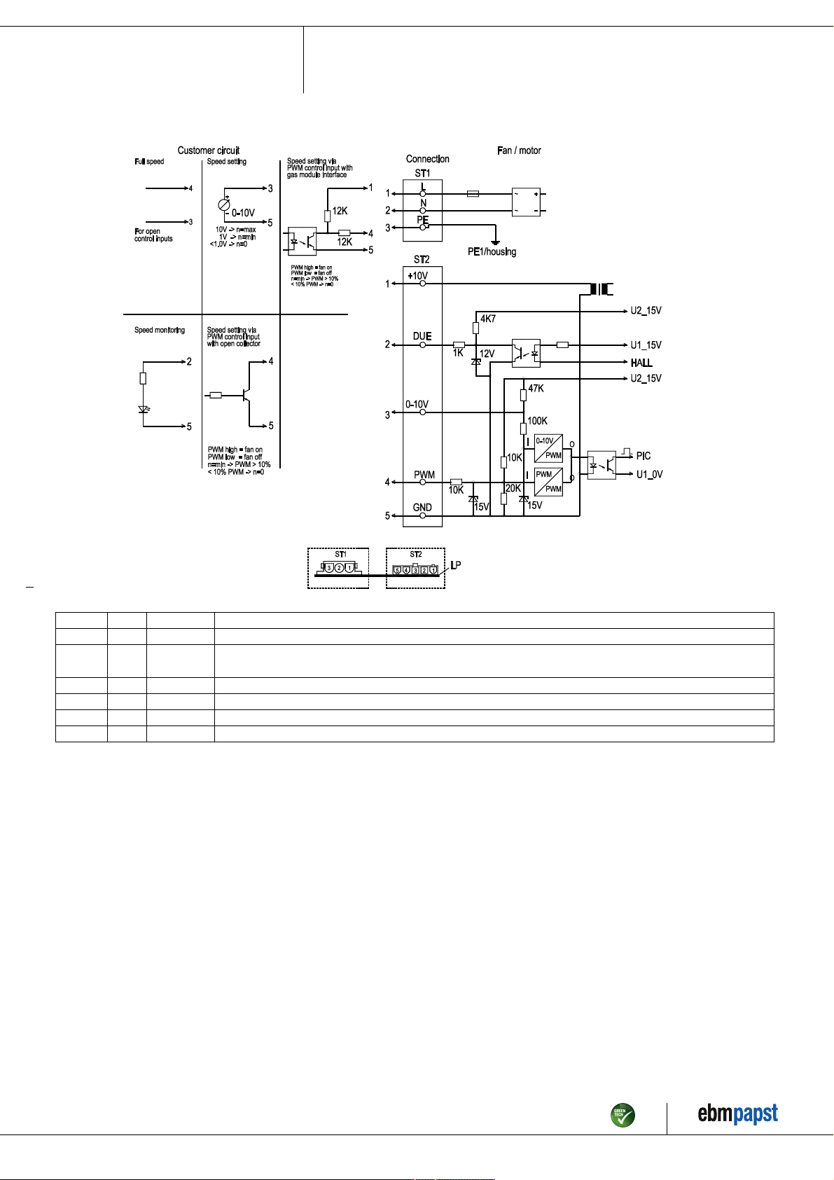
4.4 Connection diagram
Operating instructions
No. Pin Signal Function / assignment
ST1 1, 2, 3 L, N, PE Power supply 115 VAC, 50-60 Hz, phase, neutral, protective earth
ST2 1 10V/ max.
10mA
ST2 2 DUE Speed monitoring, 3 pulses per revolution, SELV
ST2 3 0-10V Control input 0-10 V, impedance 100k, SELV
ST2 4 PWM Control input PWM, 1-6 kHz, SELV
ST2 5 GND GND - Connection for control interface, SELV
Translation of the original operating instructions
Voltage output 10 VAC (+/-3%), max. 10 mA, power supply for ext. devices (e.g. potentiometer), SELV
Item no.: 51198-5-9970 · Revision: 73287 · Print-out: 2012-04-11 · Y. Uhlmann (VM-TDO) · Page 9 / 12
ebm-papst Mulfingen GmbH & Co. KG · Bachmühle 2 · D-74673 Mulfingen · Phone +49 7938 81-0 · Fax +49 7938 81-110 · info1@de.ebmpapst.com · www.ebmpapst.com
Page 10
G1G170-AB05-81
Operating instructions
4.5 Checking the connections
; Make sure that the power is off (all phases).
; Secure it from being switched on again.
; Check that the mating connector is correctly locked into the panel
connector.
; Check that the mating connector is correctly crimped to the
connection line.
4.6 Switch on device
WARNING
Hot motor housing
Fire hazard
→ Ensure that no combustible or flammable materials are
located close to the blower.
; Inspect the device for visible external damage and the proper function
of the protective features before switching it on.
; Check the air flow paths of the fan for foreign objects and remove any
that are found.
; Apply 0 VDC to the 0-10 V control input (if you are using the control
input)
; Apply 0 % PWM to the PWM control input (if you are using the
PWM control input)
; Apply the nominal voltage to the voltage supply.
; Start the device by changing the input signal.
5. INTEGRATED PROTECTIVE FUNCTIONS
The integrated protective functions cause the motor to switch off
automatically in case of faults described in the table.
Malfunctions Description / Function of
safety feature
Rotor position detection error An automatic restart occurs.
Locked rotor ; After the blockage is
removed, the motor restarts
automatically.
4.7 Switching off the device
Switching off the device during operation:
; Switch on the device via the control input.
; Do not switch the motor (e.g. in cyclic operation) on and off via power
supply.
Switching off the device for maintenance work:
; Switch on the device via the control input.
; Do not switch the motor (e.g. in cyclic operation) on and off via power
supply.
; Disconnect the device from the supply voltage.
; When disconnecting, be sure to disconnect the earth wire connection
last.
Translation of the original operating instructions
Item no.: 51198-5-9970 · Revision: 73287 · Print-out: 2012-04-11 · Y. Uhlmann (VM-TDO) · Page 10 / 12
ebm-papst Mulfingen GmbH & Co. KG · Bachmühle 2 · D-74673 Mulfingen · Phone +49 7938 81-0 · Fax +49 7938 81-110 · info1@de.ebmpapst.com · www.ebmpapst.com
Page 11

G1G170-AB05-81
Operating instructions
6. MAINTENANCE, MALFUNCTIONS, POSSIBLE
CAUSES AND REMEDIES
Do not perform any repairs on your device. Return the device to ebmpapst for repair or replacement.
WARNING
Terminals and connections have voltage even with a
unit that is shut off
Electric shock
→ Wait five minutes after disconnecting the voltage at all poles
before opening the device.
CAUTION
If the control signal of a blower that is connected to the
power system is removed, the motor can restart
automatically.
Danger of injury
→ When working on the blower, switch off the mains supply
voltage and secure it from being switched on again.
→ Wait until the device stops.
CAUTION
Electrical load after device is switched off
Electric shock in case of contact
→ Wait for five minutes after disconnecting the voltage at all
poles before touching the unit.
CAUTION
If control voltage is applied or a speed setpoint is stored,
the motor automatically restarts, e.g. after a power failure.
Danger of injury
→ Keep out of the danger zone of the device.
→ When working on the device, switch off the mains
supply voltage and secure the latter from being switched on
again.
→ Wait until the device stops.
→ After working on the device, remove any used tools or
other objects from the device.
If the blower remains out of use for some time, e.g. when in
storage, we recommend switching the blower on for at least 2
hours to allow any condensate to evaporate and to move the
bearings.
Malfunction/error Possible cause Possible remedy
Impeller running
roughly
Translation of the original operating instructions
Motor does not turn Mechanical blockage Switch off, de-
Imbalance in rotating
parts
Clean the device; if
imbalance is still
evident after
cleaning, replace the
device.
If you have
attached any weight
clips during cleaning,
make sure to
remove them
afterwards.
energise, and
remove mechanical
blockage.
Mains supply
voltage faulty
Faulty connection De-energise, correct
Thermal overload
protector responded
Overtemperature of
electronics/motor
Deflagration Leakage of the
If you have any other problems, contact ebm-papst.
Insufficient cooling Improve cooling. Let
Ambient temperature
too high
Unacceptable
operating point
handled air/gas
mixture
6.1 Cleaning
NOTE
The device does not need to be cleaned.
6.2 Safety test
NOTE
High-voltage test
The integrated EMC filter contains Y capacitors. Therefore, the
trigger current is exceeded when AC testing voltage is applied.
→ Test the device with DC voltage when you carry out the
high-voltage test required by law. The voltage to be used
corresponds to the peak value of the AC voltage required by
the standard.
What has to
be tested?
How to test? Frequency Which
Check mains supply
voltage,
restore power
supply,
apply control signal.
connection, see
connection diagram.
Allow motor to cool
off, locate and rectify
cause of error, if
necessary cancel
restart lock-out
the device cool
down.
To reset the error
message, switch off
the mains supply
voltage for a min. of
25 s and switch it on
again.
Reduce the ambient
temperature.
Reset by reducing
control input to 0.
Correct the operating
point. Let the device
cool down.
Check for leaks;
replace blower if not
properly sealed
measure?
Item no.: 51198-5-9970 · Revision: 73287 · Print-out: 2012-04-11 · Y. Uhlmann (VM-TDO) · Page 11 / 12
ebm-papst Mulfingen GmbH & Co. KG · Bachmühle 2 · D-74673 Mulfingen · Phone +49 7938 81-0 · Fax +49 7938 81-110 · info1@de.ebmpapst.com · www.ebmpapst.com
Page 12

G1G170-AB05-81
Operating instructions
Check the
protective
casing against
accidental
contact for
damage and to
ensure that it is
intact
Check the
device for
damage to
blades and
housing
Mounting the
connection lines
Mounting of
protective
earth connection
Check the
insulation of
the wires for
damage
Condensate
discharge
holes for
clogging, as
necessary
Check the ball
bearings to
ensure they
are quiet, can
move easily
and are free of
play
Visual inspection At least every
6 months
Visual inspection At least every
6 months
Visual inspection At least every
6 months
Visual inspection At least every
6 months
Visual inspection At least every
6 months
Visual inspection At least every
6 months
Manual check
by turning the
rotor in shut-off
state
At least every
6 months
Repair or
replacement of
the device
Replacement
of the device
Fasten
Fasten
Replace wires
Open bore holes
Replace
device in case
of noise,
difficulty of
movement or
clearance of
the bearings
Translation of the original operating instructions
Item no.: 51198-5-9970 · Revision: 73287 · Print-out: 2012-04-11 · Y. Uhlmann (VM-TDO) · Page 12 / 12
ebm-papst Mulfingen GmbH & Co. KG · Bachmühle 2 · D-74673 Mulfingen · Phone +49 7938 81-0 · Fax +49 7938 81-110 · info1@de.ebmpapst.com · www.ebmpapst.com
 Loading...