

Page 1

CBC000-AF08-01
Operating instructions
Programming unit for ESM range
ebm-papst Mulfingen GmbH & Co. KG
Bachmühle 2
74673 Mulfingen
Germany
Phone +49 7938 81-0
Fax +49 7938 81-110
info1@de.ebmpapst.com
www.ebmpapst.com
1. CONTENTS
1. USE 1
2. SAFETY REGULATIONS AND INFORMATION 1
2.1 Qualified personnel 1
2.2 Basic rules for safety 1
2.3 Storage 1
2.4 Disposal 1
3. INTENDED USE 2
4. PRODUCT SPECIFICATIONS 2
4.1 Scope of delivery 2
4.2 Product photo 2
1. USE
The ESM programming unit makes it possible to program two speed
levels. Models with an extended range of functions permit selection of
the direction of rotation and offer additional time-based functions. The
programming unit is compatible with virtually all the fans in the ESM
product range which are equipped with a programming interface. This
may not apply to customer-specific software versions.
2. SAFETY REGULATIONS AND INFORMATION
Observe the following warnings to guard against malfunctioning and
risks to personal safety. Make sure the fan operating instructions and
these programming unit instructions are always kept to hand at the
place of use. These instructions may be copied and distributed to provide information on potential hazards and their avoidance.
2.1 Qualified personnel
The product is only to be transported, unpacked, installed, operated,
maintained and used in any other way by appropriately qualified, trained
and authorised specialist personnel. Only authorised electricians are
permitted to install the product and to perform work on the electrical
installation.
2.2 Basic rules for safety
Always observe the following when working on the unit:
- Make sure the fan is disconnected from the power supply.
- No modifications or additions are to be made to the product and no
conversion work performed without the approval of ebm-papst.
- Modifications not approved by ebm-papst will render any warranty
claims invalid.
- Only use replacement parts which have been tested and approved by
us.
5. START-UP 2
5.1 Connection 2
5.1.1 Connecting the fan 2
5.1.2 Connecting the unit 3
6. PROGRAMMING 3
6.1 Main menu for standard ESM models 3
6.1.1 Navigation in main menu 3
6.1.2 Programming options 3
6.1.3 Transferring a parameter set to several fans (clone function) 3
6.2 Main menu for ESM models with an extended range of functions
(ESM+) 4
6.2.1 OPERATION MODE 4
6.3 Application example 5
6.4 Transferring a parameter set to several fans (clone function) 6
6.5 Resetting the programming unit 6
6.6 Switching off the programming unit 6
6.7 Ending programming routine and starting up the fan 6
CAUTION
Electric charge on the fan
Risk of injury
Always disconnect the fan from the mains before programming.
WARNING
Live terminals and connections even with fan switched
off
Electric shock
2.3 Storage
Store the product in its original packaging in a clean and dry place protected from the weather. Avoid impact and exposure to direct sunlight.
2.4 Disposal
Observe all the applicable rules and regulations in the country concerned when disposing of add-on parts.
Please ask ebm-papst for assistance with specific issues.
6.8 Updating firmware 6
Item no. 66668-4-8627 • Revision - • Release 2014-12-03 • T.Schaefer (VM-POK) • Page 1/6
ebm-papst Mulfingen GmbH & Co. KG • Bachmühle 2 • 74673 Mulfingen • Germany
Phone +49 7938 81-0 • Fax +49 7938 81-110 • info1@de.ebmpapst.com • www.ebmpapst.com
Page 2
CBC000-AF08-01
Operating instructions
Programming unit for ESM range
3. INTENDED USE
The programming unit is designed solely as an accessory for the
programming of fans from the ESM product range. Any other usage
does not conform to the intended purpose and constitutes misuse of the
product.
Improper use
- Operation of the unit in a wet or damp environment.
- Operation of the unit in the vicinity of flammable substances or
components.
- Operation of the unit in any application which does not have the
consent of ebm-papst.
Please ask ebm-papst for assistance with specific issues.
4. PRODUCT SPECIFICATIONS
The ESM programming unit is used for programming the speed of ebmpapst ESM fans. Its compact design makes it ideal for use in the field.
4.1 Scope of delivery
- ESM programming unit
- Protective cover (blue)
- AA alkaline batteries, 1.5 V (2x)
- Connecting cable (item no.: 29005-4-1040)
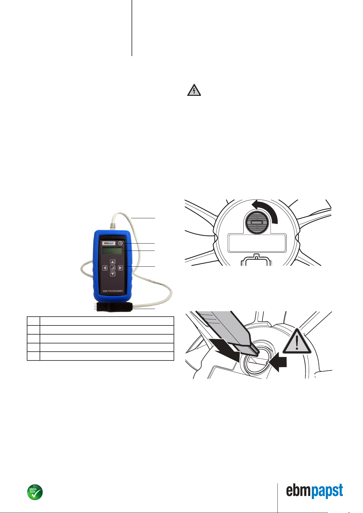
4.2 Product photo
1
5.1 Connection
5.1.1 Connecting the fan
CAUTION
Electric charge on the fan
Risk of injury
Always disconnect the fan from the mains before programming.
1. Use a broad, flat-blade screwdriver to open the cap on the fan as
shown in the illustration.
2. Give the cap a quarter turn in anti-clockwise direction.
NOTE
Damage to the cap
Turning the cap too far could damage both the cap and the
sealing system.
➔Take care not to turn the cap too far when opening and
closing.
➔Replacement caps for the programming interface can be
ordered from ebm-papst.
1 Connecting cable
2 On/Off button
3 Display
4 Navigation
5 Connector for fan
5. START-UP
NOTE
Fitting the batteries
Insert the batteries with the terminals in the correct position
as shown in the battery compartment.
Inserting the batteries the wrong way round could damage
the unit!
2
3
4
3. Insert the connector in the connection opening, using the side
groove as a guide.
4. Push in the connector until the flat part disappears completely in the
connection opening.
Take care to keep the connector absolutely straight. Never use force
5
when inserting the connector.
Item no. 66668-4-8627 • Revision - • Release 2014-12-03 • T.Schaefer (VM-POK) • Page 2/6
ebm-papst Mulfingen GmbH & Co. KG • Bachmühle 2 • 74673 Mulfingen • Germany
Phone +49 7938 81-0 • Fax +49 7938 81-110 • info1@de.ebmpapst.com • www.ebmpapst.com
Page 3

1
2
3
4
CBC000-AF08-01
Operating instructions
Programming unit for ESM range
5.1.2 Connecting the unit
1. Insert the RJ45 connector in the matching socket.
The connection for the RJ45 connector is located on the end face of
the programming unit.
2. Make sure the connector is heard to engage.
NOTE
Automatic recognition of fan type
The programming unit automatically recognises the generation of the ESM fan/motor connected. This automatic recognition function will only work if the programming unit is connected to the fan/motor before being switched on. Otherwise
the programming unit will be set to the programming mode
for the standard version.
- Switch on the programming unit by pressing and holding the "On/Off"
button until a tone sounds.
- The message ESM PROGRAMMER – POWER ON appears and the
display then switches to CHANGE SPEED 1 in the main menu. The
programming unit is then ready for use.
6. PROGRAMMING
6.1 Main menu for standard ESM models
The following options are available in the main menu for standard ESM
models:
- CHANGE SPEED 1
- CHANGE SPEED 2
- STORE INFO? (read out & save parameter set)
- PROGRAM INFO? (transfer parameter set)
- BACKLIGHT (background illumination)
- BUZZER (button sound)
- BATTERY (battery status indicator)
- VERSION (firmware version)
6.1.1 Navigation in main menu
"Select" button in centre
Arrow buttons around outside
values of the current option.
6.1.2 Programming options
CHANGE SPEED 1
"SPEED 1" is the speed at which the fan runs when the control line
(brown wire) is not connected.
If this option is chosen with the "Select" button, the currently programmed speed is displayed (speed inrpm).
This speed can be varied in steps of 10rpm - down to a minimum speed
of 700 rpm.
In the case of fans with an extended range of functions (*ESM+), the
minimum speed can be reduced to 300rpm. Speeds below 300rpm
cannot be entered; this would cause the programming unit to switch to
the "0rpm" (standby) setting in the next step.
1. Use the "Arrow right/left" buttons to set the required speed value.
Holding down the "Arrow right/left" button accelerates the rate of
change of the value.
NOTE
Observe the speed limit values
When programming, pay attention to the speed limit values
specified in the product documentation for the fan. If there is
no documentation available and no ebm-papst recommendation, never use a value higher than the speed values given on
the rating plate.
2. Press the "Select" button to confirm this value. Programming of
the fan takes just a few seconds. The message PROGRAMMING
COMPLETE appears following successful programming.
An error message will be displayed if a communication error has occurred. This is generally the result of a poor connection between the fan
and the programming unit.
➔Check the connection/connector and start the routine again.
Change Speed 2
"Speed 2" is the speed at which the fan runs when the control line
(brown wire) is connected to L (Live) or N (Neutral). If this option is
chosen with the "Select" button, the currently programmed speed is
displayed (speed inrpm). The same programming routine applies as for
CHANGE SPEED 1.
6.1.3 Transferring a parameter set to several fans (clone
function)
The clone function described below is available for the handheld programming unit as of firmware v3.2.1. The firmware version can be read
out in the "VERSION" menu.
STORE INFO? (read out & save parameter set)
The two stored speeds for the fan currently connected are displayed
in the "STORE INFO?" menu. This function can be used to transfer the
parameter set shown to the programming unit.
1. Press the "Select" button to transfer the parameter set from the fan
to the memory of the programming unit.
The message "STORING INFO" is displayed briefly during readout.
2. The parameter set read out is then automatically displayed in the
"PROGRAM INFO?" menu.
Use the "Arrow up" button or the "Arrow down" button to navigate to
the option required or to switch between the options.
- Press the "Select" button to activate the option.
- Use the "Arrow left" button or the "Arrow right" button to alter the
Item no. 66668-4-8627 • Revision - • Release 2014-12-03 • T.Schaefer (VM-POK) • Page 3/6
ebm-papst Mulfingen GmbH & Co. KG • Bachmühle 2 • 74673 Mulfingen • Germany
Phone +49 7938 81-0 • Fax +49 7938 81-110 • info1@de.ebmpapst.com • www.ebmpapst.com
Page 4

CBC000-AF08-01
Operating instructions
Programming unit for ESM range
PROGRAM INFO? (transfer parameter set)
The "PROGRAM INFO?" menu shows the parameter set currently stored
in the programming unit. This function can be used to transfer the
parameter set shown to identical fans. The programming unit does not
have to be re-started for this operation.
1. Simply connect the programming connector to the fan to which the
parameter set is to be transferred.
2. Then press the "Select" button to transfer the parameter set. The
message "PROGRAMMING COMPLETE" appears on completion of
the write operation.
3. Repeat the operation for each additional fan to which the parameter
set read out is to be transferred.
Additional information:
- If the programming unit is switched off or if it cuts out automatically
after 5 minutes of inactivity, the parameter set stored in the unit will
be retained. The parameter set last used can be called up at any time
in the "PROGRAM INFO?" menu item.
- The message "WRONG FAN CONNECTED" is output if the stored
parameter set is not compatible with the fan. In such cases, re-start
the programming unit. The parameter set of the incompatible fan can
then be read out manually and loaded again after making the corresponding changes.
Buzzer (button sound)
The button sound can be switched on or off during parameter selection
and programming by pressing the "Select" button. This does not affect
the tone sequence during switch-on and switch-off.
Backlight (background illumination)
Press the "Select" button to switch the background illumination of
the display on or off. The illumination remains switched on until it is
switched off again using the "Select" button.
Battery (battery status indicator)
Press the "Select" button to read out the battery status. The two 1.5 V
AA alkaline batteries have to be replaced on reaching a measured value
of 2.2 V. Values above this (in the range 2.3 - 3.3 V) are sufficient for
operation.
- Press the "Arrow up/down" button to return to the main menu.
Version (firmware version)
This indicates the current software version.
The latest firmware available can be found on the website
www.ebmpapst.us in the category "Support > Digital Downloads".
6.2 Main menu for ESM models with an extended range of
functions (ESM+)
Fans types with an extended range of functions (*) can be seen from the
additional designation "ESM+ enabled" on the rating plate for example.
More detailed information is also available on request from ebm-papst.
The following additional options (*) are available in the main menu of
ESM models with an extended range of functions:
- CHANGE SPEED 1
- CHANGE SPEED 2
- OPERATION MODE*
- TEST TIME*
- TIME 1*
- TIME 2*
- STORE INFO? (read out & save parameter set)
- PROGRAM INFO? (transfer parameter set)
- BUZZER (button sound)
- BACKLIGHT (background illumination)
- BATTERY (battery status indicator)
- VERSION (firmware version)
seconds) after switch-on (= application of mains voltage) for which the
fan is to run at the speed specified in "CHANGE SPEED 2". In "AUTO
DIRECTION" operation mode, this parameter can be used to implement
direction reversal after every switch-on (ROS / Reverse-On-Start).
Please note that for manufacturing reasons the test time value cannot
be set to less than 10 seconds.
- Use the "Arrow right/left" buttons to set the required value in seconds. Holding down the "Arrow right/left" button accelerates the rate
of change of the value.
- Press the "Select" button to confirm the value set. Programming of
the fan takes just a few seconds.
➔The message "PROGRAMMING COMPLETE" appears
following successful programming.
TIME 1
The parameter "TIME 1" is directly linked to the "CHANGE SPEED 1" set
value and is required solely for the operation modes "AUTO DIRECTION"
and "AUTO SPEED", which can be selected in the "OPERATION MODE"
menu.
"TIME 1" indicates the period (value range 0-100 hours) for which the
fan is to run at the speed specified in "CHANGE SPEED 1" in "AUTO
DIRECTION" or "AUTO SPEED" operation mode. The maximum possible
setting is 100 hours. The time can be varied in steps of 1 hour.
- Use the "Arrow right/left" buttons to set the required value in hours.
Holding down the "Arrow right/left" button accelerates the rate of
change of the value.
- Press the "Select" button to confirm the value set. Programming of
the fan takes just a few seconds.
➔The message "PROGRAMMING COMPLETE" appears following suc-
cessful programming.
TIME 2
The parameter "TIME 2" is directly linked to the "CHANGE SPEED 2" set
value and is required solely for the operation modes "AUTO DIRECTION"
and "AUTO SPEED", which can be selected in the "OPERATION MODE"
menu.
"TIME 2" indicates the period (value range 0-286 minutes) for which
the fan is to run at the speed specified in "CHANGE SPEED 2" in "AUTO
DIRECTION" or "AUTO SPEED" operation mode.
The maximum possible setting is 286 minutes. The time can be varied in
steps of 1 minute.
- Use the "Arrow right/left" buttons to set the required value in minutes.
Holding down the "Arrow right/left" button accelerates the rate of
change of the value.
- Press the "Select" button to confirm the value set.
Programming of the fan takes just a few seconds.
➔The message "PROGRAMMING COMPLETE" appears following suc-
cessful programming.
6.2.1 OPERATION MODE
One of the following options can be selected under "OPERATION MODE":
- MANU SPEED
- AUTO SPEED*
- MANU DIRECTION*
- AUTO DIRECTION*
"OPERATION MODE" specifies how the speed and direction of rotation
of the fan are controlled. When "OPERATION MODE" is displayed, the
options currently programmed can be seen by pressing the "Select"
button. Scroll through the four options by pressing the left or right arrow
button. Use the "Select" button to choose an option.
TEST TIME
The "TEST TIME" parameter is directly linked to the programmed
"CHANGE SPEED 2" set value and is only required for the operation
modes "AUTO DIRECTION" and "AUTO SPEED" (refer to "OPERATION
MODE" section).
The value set in "TEST TIME" indicates the period (value range 10-1000
Item no. 66668-4-8627 • Revision - • Release 2014-12-03 • T.Schaefer (VM-POK) • Page 4/6
ebm-papst Mulfingen GmbH & Co. KG • Bachmühle 2 • 74673 Mulfingen • Germany
Phone +49 7938 81-0 • Fax +49 7938 81-110 • info1@de.ebmpapst.com • www.ebmpapst.com
Page 5

CBC000-AF08-01
User guide
Programming unit for ESM range
MANU SPEED (manual speed level switching)
This is the typical standard option. The speed is switched manually
between "SPEED1" and "SPEED2" by connecting the brown control line
to or disconnecting it from L1 or N. The fan always runs in the standard
direction of rotation.
Control line not connected Set value = CHANGE SPEED 1
set value
Control line connected to L1 or N Set value = CHANGE SPEED 2
set value
- Press the "Select" button to activate the option.
AUTO SPEED (automatic, time-controlled speed level switching)
In this operation mode the set value is switched on a time-controlled
basis. The control line (brown wire) has no influence on the fan.
The speed is switched automatically between "SPEED1" and "SPEED2".
The brown control line is not required. The time for which the fan runs at
"SPEED1" is specified by "TIME1" (0-100 hours).
The time for which the fan runs at "SPEED2" is specified by "TIME2"
(0-286 minutes).
Each time it is switched on, the fan starts up at the speed programmed
for "SPEED2" for the length of time programmed in "TEST TIME"
(10-1000s).
The fan always runs in the preferred direction of rotation.
POWER ON
Set value : Set value speed 2
Rotating direction : designed
Duration : Test time
MANU DIRECTION (manual direction reversal)
The control line (brown wire) influences the set value and the direction
of rotation of the fan.
The speed and direction of rotation are switched manually with the
brown control line. If the brown control line is not connected to either L1
or N, the fan runs at "SPEED1" in the standard direction of rotation. If
the brown control line is connected to L1 or N, the fan runs at "SPEED2"
in the direction opposite to the standard direction of rotation.
Control line not
connected
Control line connected to L1 or N
Set value = CHANGE SPEED 1 set value, standard direction of rotation
Set value = CHANGE SPEED 2 set value, direction opposite to standard direction of rotation
- Press the "Select" button to activate the option.
AUTO DIRECTION
Automatic, time-controlled reverse operation: The control line (brown
wire) has no influence on the fan.
POWER ON
Set value : Set value speed 2
Rotating direction : opposite designed
Duration : Test time
Set value : Set value speed 1
Rotating direction : designed
Duration : Time 1
Set value : Set value speed 1
Rotating direction : designed
Duration : Time 1
Set value : Set value speed 2
Rotating direction : designed
Duration : Time 2
Direction of rotation
(viewed towards the rotor)
Anti-clockwise (or preferred
direction of rotation as per data
sheet)
- Press the "Select" button to activate the option.
Set value : Set value speed 2
Rotating direction : opposite designed
Duration : Time 2
- Press the "Select" button to activate the option.
6.3 Application example
"CHANGE SPEED 1" = 2000 rpm
"CHANGE SPEED 2" = 1500 rpm
"OPERATION MODE" = AUTO DIRECTION
"TEST TIME" = 10 s
"TIME 1" = 24 h
"TIME 2" = 15 min
With the above-mentioned parameters the fan runs at a speed of 2000
rpm in the standard direction of rotation.
After 24 hours the direction of rotation is reversed for 15 minutes.
During this period the fan runs at a speed of 1500 rpm in the direction
opposite to the standard direction of rotation.
Please note that after switching on the power supply the fan runs in the
direction opposite to the standard direction of rotation for a once-only
period of 10 seconds in this case (production-related test time).
NOTE
The fan should not be permanently operated in the direction
opposite to the preferred direction of rotation specified in the
data sheet, as it does not then attain optimum efficiency. For
ideal operation we recommend running the fan in the normal
direction of air flow.
IItem no. 66668-4-8627 • Revision - • Release 2014-12-03 • T.Schaefer (VM-POK) • Page 5/6
ebm-papst Mulfingen GmbH & Co. KG • Bachmühle 2 • 74673 Mulfingen • Germany
Phone +49 7938 81-0 • Fax +49 7938 81-110 • info1@de.ebmpapst.com • www.ebmpapst.com
Page 6

CBC000-AF08-01
1
2
User guide
Programming unit for ESM range
6.4 Transferring a parameter set to several fans (clone
function)
Parameter set transfer is performed in the same way for ESM models
with an extended range of functions as described above for the standard
version.
On readout, the following display appears for the additional Operation
Mode parameter:
- MS for Manual Speed
- AS for Auto Speed
- MD for Manual Direction
- AD for Auto Direction
6.5 Resetting the programming unit
In the unlikely event of the software failing to respond, press the small
white button (1) on the top to reset the programming unit.
1 Resetting the programming unit
2 Mini USB-port for uploading and upgrading firmware
6.6 Switching off the programming unit
To switch off the programming unit, press and hold
the "On/Off" button until the message "ESM PROGRAMMER - POWER
OFF" appears and the display then goes out.
If no buttons are pressed for 5 minutes, the unit switches off automatically.
6.7 Ending programming routine and starting up the fan
Before re-establishing the power supply to the motor/fan, unplug the
connecting cable and re-fit the cap.
- Give the cap a quarter turn in clockwise direction.
- Take care not to turn the cap too far.
NOTE
Before proceeding to program another ESM fan, the programming unit must be switched off and the connecting cable
unplugged and then connected to the new fan. The programming unit does not have to be switched off to program fans
with identical item numbers.
6.8 Updating firmware
The Mini USB-port on the unit can be used for upgrading software (USB
cable type Mini-B to connector type A, not included in scope of delivery).
The latest firmware can be downloaded from
www.ebmpapst.us in the category "Support > Digital Downloads" onto
a PC and loaded onto the programming unit from there. The latest instructions on software upgrade can also be found in the download portal
under "Upgrade Instructions".
Item no. 66668-4-8627 • Revision - • Release 2014-12-03 • T.Schaefer (VM-POK) • Page 6/6
ebm-papst Mulfingen GmbH & Co. KG • Bachmühle 2 • 74673 Mulfingen • Germany
Phone +49 7938 81-0 • Fax +49 7938 81-110 • info1@de.ebmpapst.com • www.ebmpapst.com
 Loading...