

Page 1
VDC-3-49.15-K4
ECI-63.XX-K4
Operating manual
Page 2

Imprint
Dated 08.2014
Copyright
ebm-papst
St. Georgen GmbH & Co. KG
Hermann-Papst-Straße 1
78112 St. Georgen
Germany
Disclaimer
Contents of the operating manual
This operating manual has been compiled with the greatest possible care. Nonetheless, ebm-papst does not provide any guarantee for the
up-to-dateness, correctness, completeness or quality of the information provided. Liability claims against ebm-papst, which relate to
material or non-material damage or losses, and which were caused by use or non-use of the information provided or by use of incorrect and
incomplete information, are excluded, provided ebm-papst is not verifiably culpable of deliberate or grossly negligent act.
Copyright and trademark law
ebm-papst remains the sole holder of the copyright. Reproduction or use without the express consent of the author is not permitted.
Use
The safety regulations must be noted and followed when using the motors. Read through this operating manual carefully, before you start
working on the drive system. Please note and follow the hazard signs and warnings to avoid personal risk and malfunctions.
This operating manual is to be treated as part of the drive system.
If the drive system is sold or passed on the operating manual must be handed over with it.
Copies can be made of the safety, assembly and installation instructions and passed on for the purpose of informing about potential hazards
and their prevention.
Subject to change without notice.
The respective current version of this operating manual is available on the ebm-papst internet site: www.ebmpapst.com
2
Page 3

Contents
1 Introduction 8
1.1 Foreword 8
1.2 Target group 8
1.3 Notation used in this document 8
1.4 Warnings and notes 9
1.5 Picture symbols 9
2 Safety Instructions 10
2.1 General safety instructions 10
2.2 Documentation 10
2.3 Standards, guidelines and directives 10
2.4 Personnel qualifications 10
2.5 Personal safety 10
2.6 Electrical / electromagnetic safety 11
2.7 Mechanical safety 11
2.8 Intended use 11
2.8.1 Type-related exclusion 11
2.9 Maintenance / repair 12
2.10 Cleaning 12
2.11 Transport / storage 12
2.12 Disposal 12
2.13 Liability and warranty 12
3 Product Description 13
3.1 Description VDC-3-49.15-K4 13
3.2 Description of the ECI-63.XX modular system K4 13
3.3 Description of the electronic classes 13
3.3.1 Functional scope of “K classes 1, 4 and 5” 13
3.4 Rating plate 14
3.4.1 Rating plate ECI-63.XX-K4 14
3.4.2 Typenschild VDC-3-49.15-K4 14
3.5 Basic configuration 15
4 Technical Specifications 16
4.1 ECI-63.20-K4 16
4.2 ECI-63.40-K4 17
4.3 ECI-63.60-K4 18
4.4 VDC-3-49.15-K4 19
4.5 Electronic properties 20
3
Page 4

Contents
5 Installation 22
5.1 Notes 22
5.2 Installing the drive 22
5.2.1 Determine screw length 22
5.2.2 Prepare the mounting plate 22
5.3 Electrical connection 23
5.3.1 Safety check 23
5.4 Connection descriptions 24
5.4.1 Connection cable VDC-3-49.15-K4 24
5.4.2 Motor connection socket ECI-63.XX-K4 24
5.4.3 Connection cable with connector ECI-63.XX-K4 25
5.4.4 Harness for Litz wire version ECI-63.XX-K4 25
5.5 Braking chopper K4 26
5.6 Functional ground connection 26
5.7 RS485 interface 26
5.8 USB-CAN-RS485 adapter 26
5.9 Connection to the USB-CAN-RS485 adapter 27
5.10 Circuit diagram 28
5.11 Schematic layout: parameterisation, commissioning (startup) and automatic operation 29
5.11.1 Parameterisation and commissioning 29
5.11.2 Automatic operation 29
5.11.3 Connecting connector at the motor 29
6 Parameterisation 30
6.1 Memory management 30
6.1.1 “RAM” memory area 30
6.1.2 “custom” memory area 30
6.1.3 “default” memory area 31
6.2 Parameter 32
7 Parameterisation of the Operating Modes 35
7.1 Application example 35
7.2 Parameterisation of the speed regulation characteristic 37
7.3 Parameterisation of the maximum current characteristic 38
7.4 Operating mode 11: Speed setpoint N1, N2, N3; Analog IN 1 40
7.5 Operating mode 12: Speed setpoints N1, A1; dynamic current limitation via A1 41
7.6 Operating mode 13: Speed setpoints A1, N1; distance 42
7.7 Operating mode 16: Speed setpoints A1, N1; rotational direction 43
7.8 Operating mode 17: Speed setpoints A1, N1; dynamic current limit via A2 44
7.9 Operating mode 18: Speed setpoints A1, N1; brake 45
4
Page 5

Contents
7.10 Operating mode 21: dynamic current limit via A1; speed setpoints A1, N2 46
7.11 Operating mode 23: dynamic current limit via A1; distance 47
7.12 Operating mode 26: dynamic current limit via A1; rotational direction 48
7.13 Operating mode 28: dynamic current limit via A1; brake 49
7.14 Operating mode 31: Distance; speed setpoints A1, N2 50
7.15 Operating mode 32: Distance; dynamic current limit via A1 51
7.16 Operating mode 34: Distance; teach 52
7.17 Operating mode 36: Distance; rotational direction 53
7.18 Operating mode 37: Distance; dynamic current limit A2 54
7.19 Operating mode 38: Distance; brake 55
7.20 Operating mode 43: Teach; distance 56
7.21 Operating mode 55: IN A / B logic via IN 1, IN 2; IN A / IN B as release (enable) 57
7.22 Operating mode 61: Rotational direction; speed setpoints A1, N2 58
7.23 Operating mode 62: Rotational direction; dynamic current limit via A1 59
7.24 Operating mode 63: Rotational direction; distance 60
7.25 Operating mode 67: Rotational direction; dynamic current limit via A2 61
7.26 Operating mode 68: Rotational direction; brake 62
7.27 Operating mode 71: Speed setpoint PWM, N2 63
7.28 Operating mode 72: Speed setpoint PWM; dynamic current limitation via PWM 64
7.29 Operating mode 73: Speed setpoint PWM, distance 65
7.30 Operating mode 76: Speed setpoint PWM; rotational direction 66
7.31 Operating mode 77: Speed setpoint PWM; dynamic current limit via A2 67
7.32 Operating mode 78: Speed setpoint PWM; brake 68
7.33 Operating mode 81: Speed setpoint frequency, N2 69
7.34 Operating mode 82: Speed setpoint frequency; dynamic current limitation via frequency 70
7.35 Operating mode 83: Speed setpoint frequency, distance 71
7.36 Operating mode 86: Speed setpoint frequency, rotational direction 72
7.37 Operating mode 87: Speed setpoint frequency; dynamic current limit via A2 73
7.38 Operating mode 88: Speed setpoint frequency, brake 74
7.39 Operating mode 91: Operation via RS485; distance / speed 75
7.40 Operating mode 98: Operation via RS485; distance / speed; brake 76
8 Inputs and Outputs 77
8.1 Input circuit 77
8.1.1 IN A / IN B control inputs 77
8.1.2 Input IN 1 and Input IN 2 78
8.1.3 Analog IN A1 79
8.2 Output circuit 79
8.2.1 Output OUT 1 / Output OUT 2 / Output OUT 3 79
5
Page 6

Contents
9 RS485 Communication 81
9.1 Communication method 81
9.2 Cycle time 81
9.3 Commands 81
9.3.1 Commands (RX) 81
9.3.2 Answer commands (TX) 82
9.4 Status byte 82
9.5 Motor status byte 83
9.6 Checksum 83
9.7 “Speed” run command 83
9.7.1 Requirements 83
9.7.2 Answer 84
9.8 “Position” run command 84
9.8.1 Requirements 84
9.8.2 Answer 85
9.9 Save parameters 85
9.9.1 Request 85
9.9.2 Answer 85
9.9.3 Error flags 86
9.10 Write parameter 86
9.10.1 Request 86
9.10.2 Answer 86
9.10.3 Error flags 87
9.11 Read parameter 87
9.11.1 Request 87
9.11.2 Answer 87
9.11.3 Error flags 88
9.12 Read status word 88
9.12.1 Request 88
9.12.2 Answer 88
9.13 Load “Parameter default values” 88
9.13.1 Request 88
9.13.2 Answer 89
9.13.3 Error flags 89
9.14 Read software ID 89
9.14.1 Request 89
9.14.2 Response (without / with bootloader) 90
6
Page 7

Contents
9.15 Read bootloader ID 90
9.15.1 Request 90
9.15.2 Answer 90
9.16 Full write access to parameters 91
9.16.1 Request 91
9.16.2 Answer 91
9.16.3 Error flags 91
9.17 Request jump back to bootloader 91
9.17.1 Request 91
9.17.2 Answer 92
9.17.3 Error flags 92
9.18 Reset customer password 92
9.18.1 Request 92
9.18.2 Answer 92
9.18.3 Error flags 93
9.19 Undefined telegrams 93
10 Parameter Description 94
10.1 Safety functions 107
11 Troubleshooting 108
11.1 Error handling 108
11.2 Operation 109
11.3 Parameterisation 110
7
Page 8

1 Introduction
1.1 Foreword
This operating manual describes the possible uses, the assembly and/or installation, operation and programming of the products listed on
the front page.
All the safety instructions listed under Chapter 2 must be followed at all times during the installation and operation of the drive system;
outside of Germany the relevant laws, directives, guidelines and regulations of the respective country also apply.
Read through this operating manual carefully before starting any work on the drive system. Note and follow the following warnings in order
to avoid personal risk or product malfunctions.
This operating manual is to be thought of and handled as part of the drive system and must be handed over with the drive system if it is sold
or passed on.
The safety instructions can be copied and passed on to provide information about potential hazards and their prevention.
Depending on the version or revision status of the products, differences may exist compared to this operating manual. The user must check
this before using the manual and take into account any such differences.
1.2 Target group
This operating manual is solely directed at qualified and trained skilled personnel with knowledge of electronics and mechanics.
1.3 Notation used in this document
In this operating manual the significance of texts is denoted by different presentation forms.
Descriptive text is presented without preceding symbol.
• Textwithaprecedingdot(•)indicatesalistwhichisintroducedbyaheading.
– Text with a preceding dash (–) is on a lower level below the list with a dot.
Underlined blue text denotes a cross-reference, which can be clicked in the PDF document. The part of the document named in the text is
then displayed.
Text in Courier font
is used to represent command sequences in software programs.
8
Page 9
1 Introduction
1.4 Warnings and notes
Warnings and notices are always positioned before the instruction, implementation of which can result in a hazard or property damage.
The following warnings are used in this document:
Hazard.
This notice denotes a hazard with high risk, which will result in imminent fatality or serious physical injuries if it is not
DANGER
WARNING
CAUTION
avoided.
f This arrow indicates the appropriate precaution to take to avert the hazard.
Hazard.
This notice denotes a hazard with moderate risk, which can possibly result in fatality or serious physical injuries if it is not
avoided.
f This arrow indicates the appropriate precaution to take to avert the hazard.
Hazard.
This notice denotes a hazard with low risk, which can result in minor or moderate physical injuries or property to damage
if it is not avoided.
f This arrow indicates the appropriate precaution to take to avert the hazard.
Notices contain information, which are particularly important in the corresponding position or which facilitate the described operating steps,
are highlighted as follows:
This notice gives you use recommendations and helpful tips.
NOTE
1.5 Picture symbols
The following pictograms, where applicable in combination, are used on the ebm-papst products and packagings as hazard warnings.
General warning.
High voltage sign (Electric shock).
Hot surface warning sign.
Crushing hazard / hand injury warning sign.
9
Page 10

2 Safety Instructions
The VDC-3-49.15-K4 and ECI-63.XX-K4 drive systems have been developed to the latest electronic and electrical engineering standards as
well as recognised guidelines for the safety and protection of users.
The drive systems may only be operated and serviced by authorised skilled personnel, who have read through and understood the complete
operating manual. The drive systems must be used with the necessary care, in compliance with all safety instructions described in this
operating manual and the local company-specific regulations.
Read all safety information and instructions and keep notices and the operating manual in the same place as the drive systems.
2.1 General safety instructions
• Before starting work, disconnect the drive system or the design application using suitable devices provided and secure it against being
switched back on again.
• Before opening the units or entering the danger zone, safely bring all drives to a standstill and secure them against being switched back
on again.
• Do not make any changes, add attachments or make modifications to the drive system without ebm-papst's approval.
• If the motor is subjected to unapproved loads, check it for damage and if necessary repair or replace it.
• Do not commission or start up the design application until it has been fully checked for compliance with all relevant legal requirements,
directives and guidelines and the safety provisions relevant for its intended use (e.g. accident prevention regulations and technical
standards).
• Re-assess any safety risks caused by the drive system after it has been installed in the design application.
2.2 Documentation
In addition to this operating manual, the “Kickstart” PC software is required for making settings and parameterisation (configuration) of the
motors. The “ebm-papst Kickstart” software manual describes how it functions.
2.3 Standards, guidelines and directives
• The product does not fall under the Low Voltage Directive 2006/95/EC, as the nominal operating voltage is not within the voltage range
from 75 V DC and 1500 V DC.
• The Machinery Directive MD is applicable, as the product is “partly completed machinery” in accordance with Article 2, paragraph g),
MD 2006/42/EC. A “CE” marking does not have to be provided on the rating plate. However, a Declaration of Incorporation must be drawn
up in accordance with Annex II, Part 1, Section B, MD 2006/42/EC.
2.4 Personnel qualifications
• Only qualified electricians may install the drive system and carry out the trial run and work on the electrical system.
• The drive system may only be transported, unpacked, operated and serviced by instructed and authorised skilled personnel.
2.5 Personal safety
• Provide adequate safeguards / contact protection.
• Wear suitable clothing.
• Do not wear loose clothing or jewellery.
• Keep hair, clothing and gloves away from rotating components.
• Wear personal protective equipment (hearing protection, thermal protection gloves).
10
Page 11

2 Safety Instructions
2.6 Electrical / electromagnetic safety
• Check the electrical equipment of the drive system regularly.
• Only use cables and connectors approved by ebm-papst.
• Remove defective cables and loose connections immediately.
• Take suitable measures to avoid impermissible electromagnetic interference emissions.
• Take suitable measures against high-frequency EMC radiation.
• Ensure EMC capability in the terminal device / installation state.
• Use control devices to control the electromagnetic radiation.
2.7 Mechanical safety
• Only carry out work when the system / machine is at a standstill.
• Provide adequate cooling of the drive.
• Remove protective devices and guards on the drive system and design application only for the purpose of carrying out repair and
assembly work.
2.8 Intended use
• The drives of the VDC-3-49.15-K4 and ECI-63.XX-K4 series are intended for installation in stationary industrial design applications and
machines and may only be operated electrically when installed!
• Commissioning or starting up is therefore prohibited until it has been established that the drive system together with the design
application, in which the drive is installed, satisfy the safety and protection requirements of the Machinery Directive.
• This product is not intended for consumers! Use in a home environment is not planned, without further testing and deployment of
appropriately adapted EMC protection measures!
• The electronic module is an installation product. It is only intended for use within other equipment or units and has no independent
function. It is not intended for passing on to end users or consumers.
• All motor - electronic combinations must be qualified by the end manufacturer within their intended application and validated for overload
and blocking safety. The application manufacturer is responsible for the end product and must ensure that adequate safety precautions
are taken.
2.8.1 Type-related exclusion
Due to its type or design, the drive system must not be used in the following areas of use; this could result in and hazards and equipment
damage:
• In case of special fail-safe requirements.
• In aircraft and space vehicles.
• In rail and motor vehicles.
• In boats and ships.
• In potentially explosive atmospheres (EX protection area).
• For operation near flammable materials or components.
• For use as a safety component or for carrying out safety-relevant functions.
11
Page 12

2 Safety Instructions
2.9 Maintenance / repair
• The control electronics are maintenance-free for the period of the planned life.
• Repairs on the product may only be made by qualified personnel or ebm-papst.
2.10 Cleaning
Damage or malfunction if the unit is cleaned by
• cleaning with a water spray or high-pressure (jet) cleaner.
• Use of acids, alkalis and solvent-based cleaning agents.
• Use of pointed and sharp-edged objects.
2.11 Transport / storage
• Transport the motor only in its original packaging.
• Secure the transport goods.
• Do not exceed the vibration values, temperature and climate ranges during the whole transport (refer to technical data from page 16).
• Store the drive system, dry and protected in its original packaging, in a clean environment.
• Do not store the drive system for longer than 1 year.
• Keep to the specified ambient temperature range (refer to technical data from page 16).
2.12 Disposal
On disposing of the product, note and follow all legal and local regulations and requirements applicable in your country.
2.13 Liability and warranty
ebm-papst GmbH & Co. KG does not accept any liability or provide any warranty whatsoever for incidents due to
• Failure to follow this operating manual.
• Incorrect handling and use of the drive system.
• Improper handling.
• Incorrect storage.
• Unsecured transport.
• Use of accessories and spare parts of other manufacturers without the express and written approval of ebm-papst GmbH & Co. KG.
• Changes to the drive system without the express and written approval of ebm-papst GmbH & Co. KG.
12
Page 13
3 Product Description
3.1 Description VDC-3-49.15-K4
The VDC-3-49.15-K4 motor is a 3-phase EC drive with a multi-pole magnetised neodymium magnet. The electronically commuted external-
rotor motor has an astonishingly high power density and a compact design. Excellent control action is achieved due to the field-orientated
control with sinus commutation. The VDC-3-49.15-K4 has fully integrated control electronics with high-performance DSP and extensive
interfaces. This enables particularly flexible control of the drive and the drive can therefore be adapted to different applications. The
integrated temperature cut-out provides reliable protection against overload.
Rated wattages from 100 to 150 watt are available to choose from.
3.2 Description of the ECI-63.XX modular system K4
The ECI-63.20-K4, 63.40-K4 and 63.60-K4 motors are EC drives. The Series ECI electronically commutated internal rotor motors excel with
large power density and dynamic performance. The ECI-63.XX modular system K4 has fully integrated class 4 control electronics with several
analog and digital interfaces. These can be parameterised via an RS485 interface. This enables particularly flexible control of the drive and
the drive can therefore be adapted to different applications.
Nominal outputs from 150 to 400 W with corresponding packet lengths from 20 to 60 mm are available to choose from.
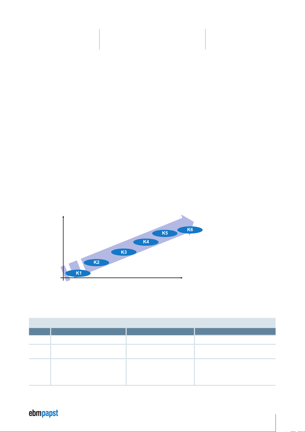
3.3 Description of the electronic classes
ebm-papst uses the designation “K class” to describe the functional scope of an ebm-papst motor system. The higher the digit the greater
the functional scope. Of the planned classes 1 – 6, to date classes K1, K4 and K5 are in use.
Intelligence
16-bit DSP
8-bit processor
No processor
Functions
Overview of the electronic classes
3.3.1 Functional scope of “K classes 1, 4 and 5”
Class Motor type Commutation
K1
K4
K5
Motor with rotor position encoder external Detection of the rotor position
Motor with enhanced motor control basic
features
Motor with enhanced motor control
Sinus commutation with field-orientated
control up to n = 0
Sinus commutation with field-orientated
control up to n = 0
Function
Speed controller
Current controller
Position controller
Speed controller
Current controller
Position controller
Enhanced safety functions
Bus system, e.g. CANopen, parameterisable
Firmware download, etc.
13
Page 14
3 Product Description
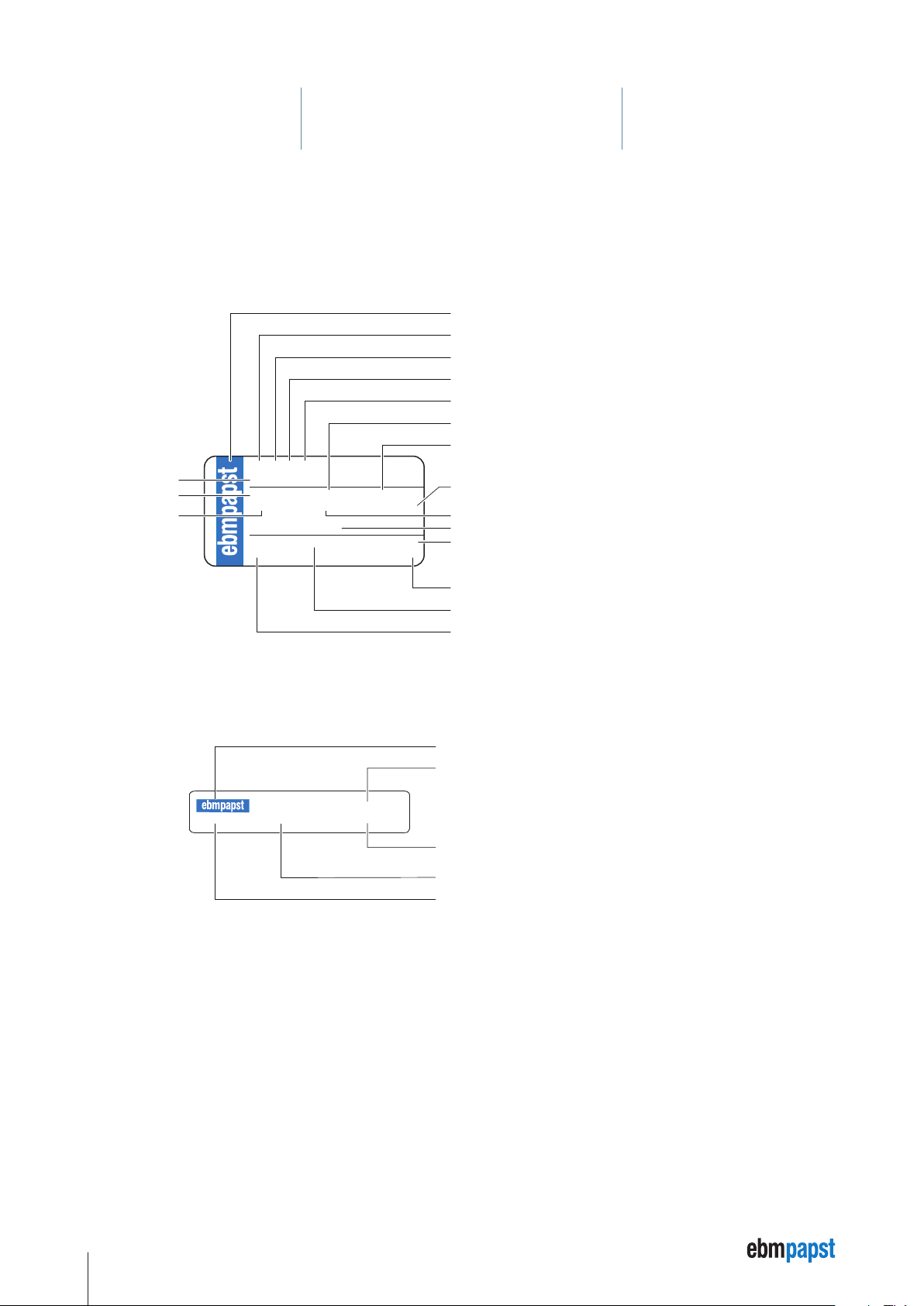
3.4 Rating plate
The rating plate with the respective features of the ECI-63.XX-K4 and VDC-3-49.15-K4 motors is attached to the housing.
3.4.1 Rating plate ECI-63.XX-K4
Company logo
Motor type, ECI = Electronically Commutated Internal Rotor Motor
Diameter of motor housing = 63 mm
Overall length
Electronic class
Nominal torque
Nominal speed
ECI 63.20-K4
Product No.
Nominal voltage
Class of protection
9326320400
24 VDC 425 mNm 4000 U/min
IP 54 E 8,5 A
US-Pat. 7230359B2
ebm- papst St. Georgen 04/13
DE (S) xx
Power consumption
Thermal class
US patent No.
Production date MM/YY
3.4.2 Typenschild VDC-3-49.15-K4
937 4915 400
24 VDC 04/2014 2465 5497
Serial number
Production plant
Country code
Company logo
Product number
Serial number
Production date MM/YY
Nominal voltage
14
Page 15
3 Product Description
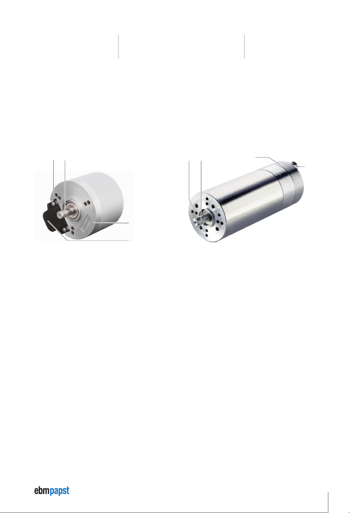
3.5 Basic configuration
In the VDC-49.15-K4 drive system the control electronics (3) is attached on the motor output end (1). The connection cable is preinstalled in
the control electronics (3) in the factory. The motor housing on the output shaft (2) is formed as a flange with various drillholes for fixing and
attaching the transmission.
In the drive systems of the ECI-63.XX modular system K4 series, the motor housing and control electronics (3) are configured with same
diameter. All necessary electrical connections (4) are integrated in the control electronics (3). The motor housing is formed as a flange at the
output shaft (2) with various drillholes for fixing and attaching the transmission.
VDC-49.15-K4 ECI-63.XX-K4
1
2
3
2
1
3
4
4
1 Motor output side with fixing option or transmission attachment
2 Output shaft
3 Integrated power and control electronics
4 Power, signal and RS485 link
15
Page 16

4 Technical Specifications
F
This chapter contains the nominal technical data of the following motors:
• ECI-63.20-K4 / ECI-63.40-K4 / ECI-63.60-K4 and
• VDC-3-49.15-K4
and extended technical data for all sizes (see page 20).
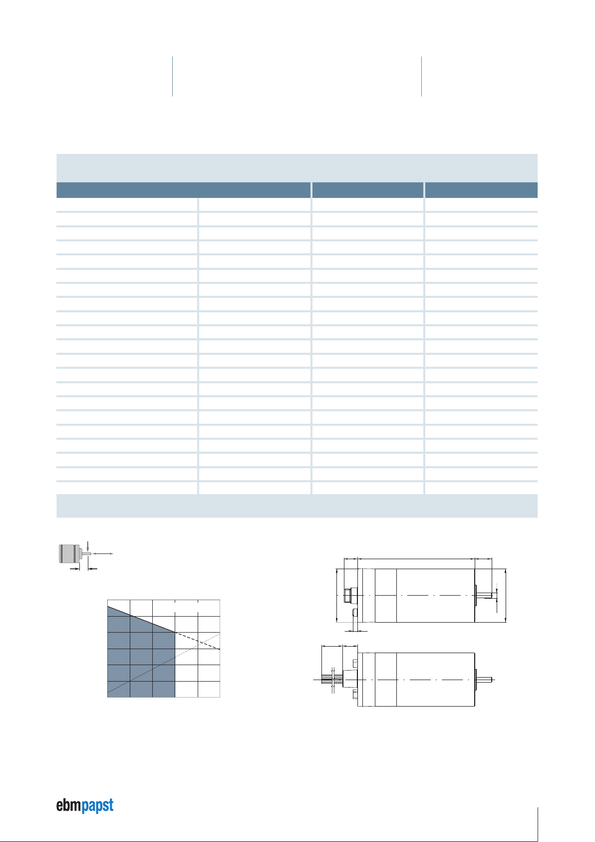
4.1 ECI-63.20-K4
Nominal data
Type Unit ECI-63.20-K4-B00 ECI-63.20-K4-D00
Nominal voltage (UN) V DC 24 48
Allowable supply voltage range (U
Nominal speed (n
Nominal torque (M
Nominal current (I
Nominal output power (P
Free-running speed (n
Free-running current (I
) rpm 4000 4000
N
) mNm 425 450
N
) A 8.5 5.4
N
N
) (no-load speed) rpm 5600 6000
L
) (no-load current) A 0.50 0.30
L
Max. reverse voltage V DC 35 58
Setpoint input – Analog / PWM / Frequency / Digital Analog / PWM / Frequency / Digital
Recommended speed control range rpm 0 … 5000 0 … 5000
Locked rotor protection – thermal thermal
Protection on overload – yes yes
Starting torque mNm 3.5 × M
Rotor moment of inertia (JR) kgm2 × 10
Thermal resistance (R
) K / W 3.6 3.6
th
Degree of protection (IP rating) IP 40 / IP 54* IP 40 / IP 54*
Allowable ambient temperature range (T
Motor mass (m) kg 0.85 0.85
Order No. (ECI-63.20-K4-S) Connector type 932 6320 400 932 6320 402
Order No. (ECI-63.20-K4-L) Stranded (litz) wire type 932 6320 403 932 6320 405
Subject to change without notice * The degree of protection (IP 54) given refers to the connector type and the installed condition with
) V DC 20 … 28 40 … 53
ZK
) W 178 188
-6
) °C 0 … +40 0 … +40
U
N
19 19
seal on the flange side.
4.2 × M
N
F
radial
F
axial
150 N
axial
F
150 N L
radial
1
20 mm
Allowable shaft load at nominal speed and life
L
1
expectancy L10 about 20000 h**.
ECI-63.20-K4-B00
5000
4000
]
–1
3000
2000
Speed [min
1000
M
I
100 200 300 400 500
Torque [mNm]
16
15,0
12,0
9,0
6,0
Current intensity [A]
3,0
0
Dimensions ECI-63.20-K4,
Connector type
16,3
Ø63,5
5,8
18,4500±10
118,5
±0,3
Stranded wire type (cable harness is supplied separately)
±0,3
20
+0,1
-0,3
g5
Ø63
Ø6
Page 17
4 Technical Specifications
F
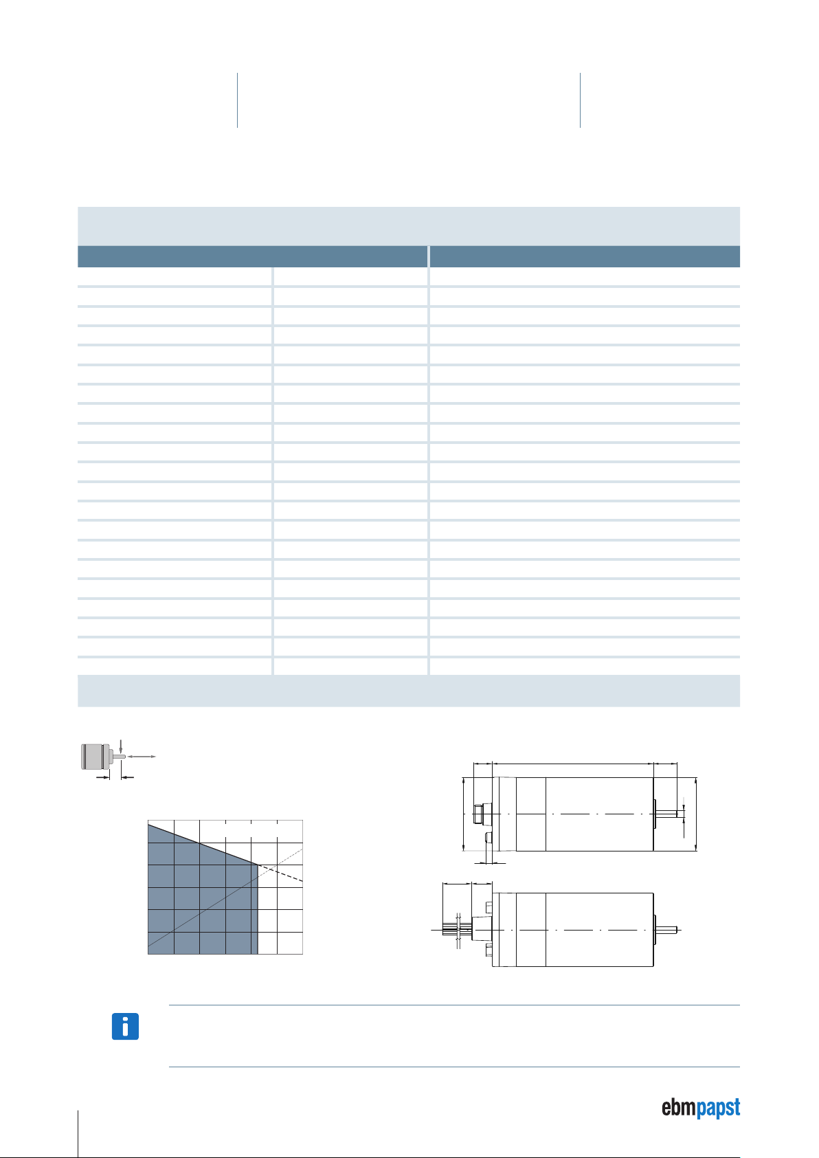
4.2 ECI-63.40-K4
Nominal data
Type Unit ECI-63.40-K4-B00 ECI-63.40-K4-D00
Nominal voltage (UN) V DC 24 48
Allowable supply voltage range (U
Nominal speed (n
Nominal torque (M
Nominal current (I
Nominal output power (P
Free-running speed (n
Free-running current (I
) rpm 4000 4000
N
) mNm 600 750
N
) A 12.3 7.2
N
N
) (no-load speed) rpm 5600 5400
L
) (no-load current) A 0.90 0.46
L
Max. reverse voltage V DC 35 58
Setpoint input Analog / PWM / Frequency / Digital Analog / PWM / Frequency / Digital
Recommended speed control range rpm 0 … 5000 0 … 5000
Locked rotor protection – thermal thermal
Protection on overload – yes yes
Starting torque mNm 2.5 × M
Rotor moment of inertia (JR) kgm2 × 10
Thermal resistance (R
) K / W 2.9 2.9
th
Degree of protection (IP rating) IP 40 / IP 54* IP 40 / IP 54*
Allowable ambient temperature range (T
Motor mass (m) kg 1.15 1.15
Order No. (ECI-63.40-K4-S) Connector type 932 6340 400 932 6340 402
Order No. (ECI-63.40-K4-L) Stranded (litz) wire type 932 6340 403 932 6340 405
Subject to change without notice * The degree of protection (IP 54) given refers to the connector type and the installed condition with
) V DC 20 … 28 40 … 53
ZK
) W 251 314
-6
) °C 0 … +40 0 … +40
U
N
38 38
seal on the flange side.
4 × M
N
F
radial
F
axial
150 N
axial
F
150 N L
radial
1
20 mm
Allowable shaft load at nominal speed and life
L
1
expectancy L10 about 20000 h**.
ECI-63.40-K4-B00
5000
4000
]
–1
3000
2000
Speed [min
1000
200 400 600 800
M
I
Torque [mNm]
25,0
20,0
15,0
10,0
Current intensity [A]
5,0
0
Dimensions ECI-63.40-K4,
Connector type
16,3
Ø63,5
5,8
18,4500±10
138,5
±0,3
Stranded wire type (cable harness is supplied separately)
±0,3
20
+0,1
-0,3
g5
Ø63
Ø6
17
Page 18
4 Technical Specifications
F
4.3 ECI-63.60-K4
Nominal data
Type Unit ECI-63.60-K4-D00
Nominal voltage (UN) V DC 48
Allowable supply voltage range (U
Nominal speed (n
Nominal torque (M
Nominal current (I
Nominal output power (P
Free-running speed (n
Free-running current (I
) rpm 4000
N
) mNm 850
N
) A 8.6
N
N
) (no-load speed) rpm 5800
L
) (no-load current) A 0.60
L
Max. reverse voltage V DC 58
Setpoint input Analog / PWM / Frequency / Digital
Recommended speed control range rpm 0 … 5000
Locked rotor protection – thermal
Protection on overload – yes
Starting torque mNm 3 × M
Rotor moment of inertia (JR) kgm2 × 10
Thermal resistance (R
) K / W 2.5
th
Degree of protection (IP rating) IP 40 / IP 54*
Allowable ambient temperature range (T
Motor mass (m) kg 1.5
Order No. (ECI-63.60-K4 S) Connector type 932 6360 402
Order No. (ECI-63.60-K4 L) Stranded (litz) wire type 932 6360 405
Subject to change without notice * The degree of protection (IP 54) given refers to the connector type and the installed condition with
) V DC 40 … 53
ZK
) W 356
-6
) °C 0 … +40
U
57
N
seal on the flange side.
radial
F
L
1
5000
4000
]
–1
3000
2000
Speed [min
1000
F
150 N
axial
F
150 N L
radial
axial
1
Allowable shaft load at nominal speed and life
expectancy L10 about 20000 h**.
ECI-63.60-K4-D00
M
I
200 400 600 800 1000
Torque [mNm]
20 mm
12,5
10,0
7,5
5,0
Current intensity [A]
2,5
0
Dimensions ECI-63.60-K4
Connector type
16,3
Ø63,5
5,8
18,4500±10
158,5
±0,3
Stranded wire type (cable harness is supplied separately)
±0,3
20
+0,1
-0,3
g5
Ø63
Ø10
Extended technical data is available on request.
NOTE
18
Page 19
4 Technical Specifications
500
±10
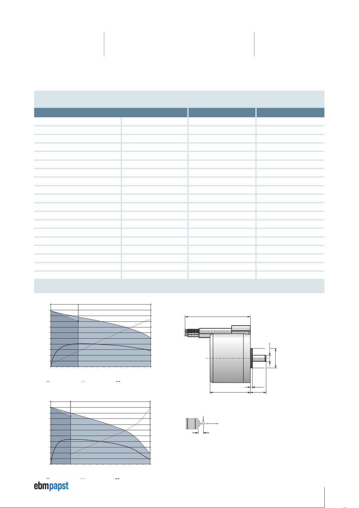
VDC-3-49.15-K4 D00, 48V (at 25°C / 120°F)
4.4 VDC-3-49.15-K4
Nenndaten
Typ Einheit VDC-3-49.15-K4 B00 VDC-3-49.15-K4 D00
Nominal voltage (UN) V DC 24 48
Allowable supply voltage range (U
Nominal speed (n
Nominal torque (M
Nominal current (I
Nominal output power (P
Free-running speed (n
Free-running current (I
) rpm 4000** 4000**
N
) mNm 235** 300**
N
) A 5** 3,2**
N
N
) rpm 5000 5000
L
) A 1.0 0.6
L
Max. reverse voltage V DC 35 58
Set value input Analog / PWM / Frequency / Digital Analog / PWM / Frequency / Digital
Recommended speed control range rpm 0 … 4500 0 … 4500
Function for motor protection at stall thermal thermal
Overload protection yes yes
Starting torque mNm 850 1500
Rotor moment of inertia (J
Protetcion class IP 54* IP 54*
Ambient temperature range (T
Motor mass (m) kg 0.56 0.56
Order No. 937 4915 400 937 4915 402
Subject to change without notice * Classification of protection class refers to installed state with sealing on the flange side.
) V DC 20 … 28 40 … 53
ZK
) W 100** 125**
) kgm2 × 10
R
) °C / °F 0 … +40 / -22 … +104 0 … +40 / -22 … +104
U
-6
108 108
max. 40 °C / 104 °F
** T
U
VDC-3-49.15-K4 B00, 24V (at 25°C / 77° F)
5500
5000
4500
4000
3500
]
-1
3000
2500
2000
1500
Speed n [min
1000
500
0
Continous
operation
n = Speed, f (M) I = Current, f (M) η = Efficiency, f (M)
5500
5000
4500
4000
]
-1
Speed n [min
3500
3000
2500
2000
1500
1000
500
0
Mn Mmax
Operating
point
Continuous
operation
300 400 500 600 700 800 900 1000 1100 1300 1400 1500
200
n = Speed, f (M) I = Current, f (M) η = Efficiency, f (M)
M
n Mmax
Operating
point
Short-time operation
350 400 450 500 550 650 700 750 800 850
6000 50 100 150 200 235 300
Torque M [mNm]
Short-time operation
12000 100
Torque M [mNm]
22
20
18
16
14
12
10
8
6
4
2
Current I [A]; Efficiency η*10 [%]
0
22
20
18
16
14
12
10
8
6
4
2
Current I [A]; Efficiency η*10 [%]
0
Dimensions VDC-3-49.15-K4
Connector type
52
±0,5
Protective cap in aluminium natural.
F
radial
L
1
F
20 N
axial
F
60 N L
radial
F
axial
Allowable shaft load at nominal speed and life
expectancy L10 about 20000 h**.
0,0 1
0,0 06
_
_
+
+
Ø 8
Ø 25 h8
2,5
±0,1
20
±0,3
10 mm
1
19
Page 20

4 Technical Specifications
4.5 Electronic properties
Inputs IN A, IN B
Properties Unit Value / Comment
Input level – PLC level
Low level V < 5
High level V > 15
Protection against polarity reversal and voltages V ≤ 30
if case of cable break – Logic level “0”
Input impedance kΩ 5.4
Input frequency kHz ≤ 10
Input dynamic (Tau) ms ≤ 0.1
Applied logic level – IN A = B = 0 = output stage switched off, FK 5
Subject to change without notice
IN A or B = 1 = output stage switched on
Inputs IN 1, IN 2
Properties Unit Value / Comment
Input level – PLC level
Low level V < 5
High level V > 15
Protection against polarity reversal and voltages V ≤ 30
if case of cable break – Logic level “0”
Input impedance kΩ 5.4
Maximum input frequency for command source via PWM / frequency kHz 15
Input dynamic (Tau) ms ≤ 0.1
Subject to change without notice
Outputs (PNP)
Properties Unit Value / Comment
Output level – High side driver dependent on U
Low level V Open source
High level V > U
Protection against polarity reversal and voltages V ≤ 30
Output current / channel mA ≤ 100
Peak output current / channel A approx. 600 mA (thermally dependent)
Short-circuit proof – yes
Polarity reversal protection – no
Overload protected – yes (automatic thermal cut-out)
Output frequency @ I
Subject to change without notice
= 100 mA kHz ≤ 1
out
(logic supply)
- 2
Logic
Logic
20
Page 21

4 Technical Specifications
Analog inputs “Analog IN 1…2” (signal connector, differential to GND
Analog
)
Properties Unit Value / Comment
Input voltage range (analog IN) V 0 to 10
GND reference (differential measurement) – Analog GND
Input frequency kHz ≤ 1
Internal resistance kΩ 8
Signal resolution bit 10
Measuring tolerance (relative to the end value 10 V) % ≤ 2
Protection against polarity reversal and voltages V ≤ 28
Subject to change without notice
RS485 bus interface
Properties Unit Value / Comment
Functional scope – –
Baud rate kbit/s 115
Dielectric strength V -8 V to +13 V
Internal bus termination ohm 12k
Subject to change without notice
Safety and monitoring functions
Properties Unit Value / Comment
Functional scope – • Temperature monitoring of the output stage
Temperature cut-out point output stage (PC software)
(Hysteresis: 10 K),
Error must be acknowledged again by means of software
overvoltage cut-out
U
ZK
(Hardware, hysteresis: 1V)
undervoltage auto restart
U
ZK
(software, cut-off U
The error must be acknowledged.
Overload protection I²t (software) – yes
Hardware overcurrent protection circuit as max. current per winding
limitation
Resolution of single turn absolute encoder Bit / revolution 10 (accuracy approx. 3°)
Subject to change without notice
Logic
at 16V),
°C 120
V 63
V 18
A
• Under and overvoltage monitoring of the
system voltages incl. UB overcurrent
limitation
• Overload protection through I²t
45 for VDC-3-49.15-K4
53 for ECI-63.XX-K4
21
Page 22
5 Installation
3x
Ø3,7
This chapter describes the mechanical and electrical connection of the drive systems.
5.1 Notes
The drives must be checked for visible damage before installation. Damaged drive system must not be installed.
The drives must be fixed onto a flat surface with at least 4 screws. The screws must be secured with suitable measures against loosening.
Use thread-forming screws to DIN 7500 for the fixing.
5.2 Installing the drive
Risk of damage!
CAUTION
CAUTION
When the drives are installed in the motor housing it can be damaged by high radial loads, if the tightening torque applied
to the fixing screws is too high or if the fixing screws are too long.
f Do not load the motor shaft, either radially or axially, with more than 150 N.
f Tighten fixing screws M4 with 3
±0.2
Nm maximum, M5 with 4
±0.2
Nm maximum.
f Do not exceed the specified maximum length of the fixing screws (see Chapter “5.2.1 Determine screw length”).
Risk of damage to electronic components!
The discharge of static charge during installation of the drives can damage the electronic component.
f Use ESD protective equipment during installation.
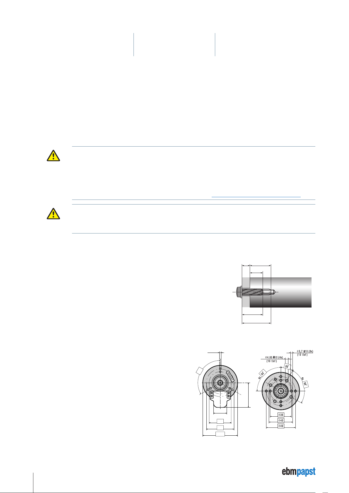
5.2.1 Determine screw length
X E
A minimum screw length S
is required for safe and reliable fixing of the motors.
min
The maximum allowable screw length S
Minimum screw length S
Minimum depth of engagement E
Maximum screw length S
Maximum depth of engagement E
=
min
6.5 mm + material thickness X of the mounting plate.
min
=
max
8.0 mm + material thickness X of the mounting plate.
min
prevents damage to the motor.
max
max
E
min
S
min
S
max
5.2.2 Prepare the mounting plate
120˚
±0,04
±0,5
44,65
±0,2
24
Ø40
Ø50
±0,2
Ø63
Sketch of fixing holes, motor
housing ECI-63.XX-K4
Only use the drillholes on the output side of the motors housing to fix the drive.
To this end, transfer the necessary drillholes for the centring collar of the motor,
pitch circle and size of the fixing holes onto the mounting plate and drill (see
sketch).
Sketch of fixing holes, motor
housing VDC-3-49.15-K4
22
Page 23

5 Installation
5.3 Electrical connection
The connection cable for the VDC-3-49.15-K4 drive system is attached to the motor in the factory, no additional plugs are required for the
electrical connection and parameter setting.
The following is required for the electrical connection and parameter setting of the ECI-63.XX-K4 drive system:
1 Connection cable with 15 pin connector M16 (not for the Litz wire (stranded wire) variant of the ECI-63.XX-K4, see Chapter 5.4.4 Harness
for Litz wire version ECI-63.XX-K4, page 25).
1 ebm-papst USB-CAN-RS485 adapter (screw terminal adapter board to the D-SUB 9 connection, USB connection cable to the PC).
1 ebm-papst “Kickstart” PC software.
Health hazard!
The drive systems are installed in design applications in which electrical and electromagnetic components are used.
DANGER
NOTE
These can affect pacemakers, metallic implants or hearing aids and cause severe personal harm.
f Avoid the immediate vicinity, especially areas identified by the warning symbol
implants or wear a hearing aid.
• The drive systems are built-in parts and do not have any electrical disconnecting switches.
• Connect the product to suitable electrical circuits only. Please note that the power supply units must have suitable
protection against regenerative voltage generated on the secondary side.
• When working on the drive system the system / machine must always be disconnected from the power supply and
secured against being switched back on again.
, if you have a pacemaker, metal
5.3.1 Safety check
Before connecting the drive system, check:
• Supply voltage and product voltage identical?
• Does the rating plate data match the connection data of the power supply unit?
• Connection cable suitable for the current intensity and the ambient conditions and area of use?
23
Page 24

5 Installation
5.4 Connection descriptions
• The connection cable of the VDC-3-49.15-K4 motors is pre-installed on the motor in the factory.
NOTE
5.4.1 Connection cable VDC-3-49.15-K4
The pin assignment of the connection socket is as follows:
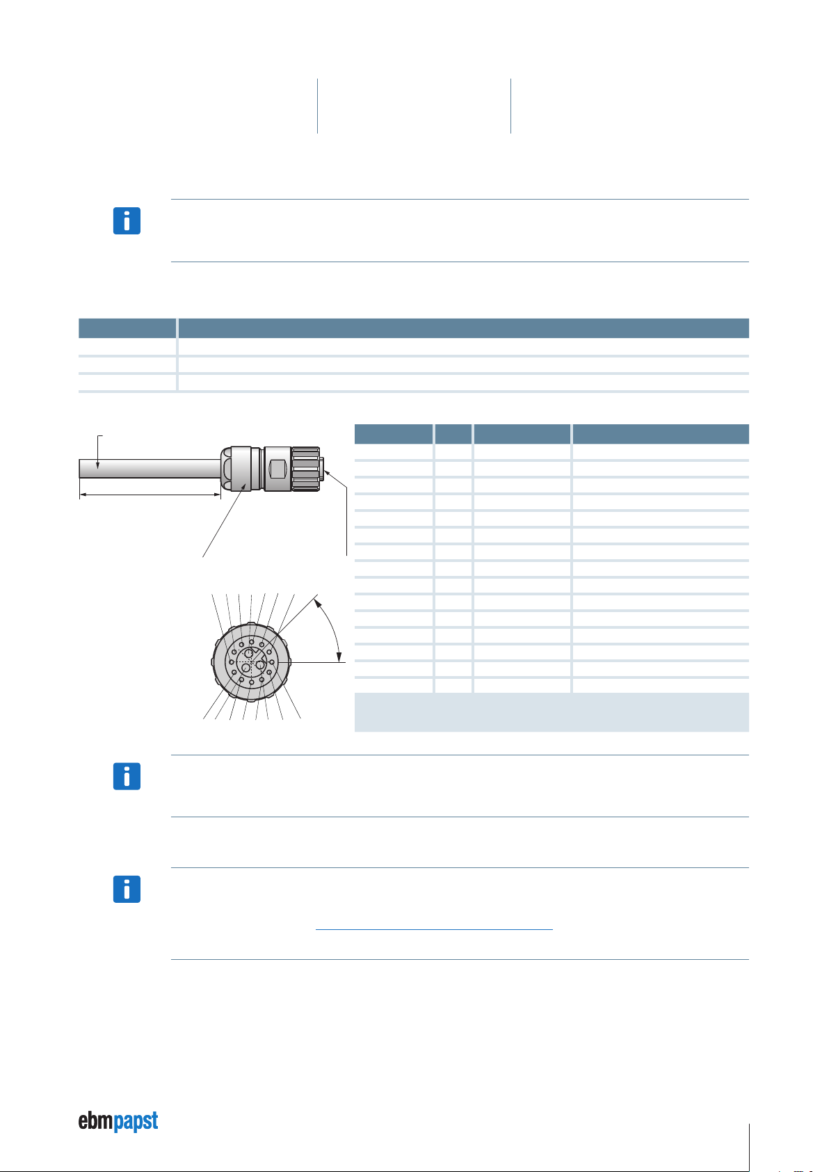
• The ECI-63.XX-K4 motors have a 15 pin connector M16 (12+3) on the motor. This is used for the connection of a
connector variant connector cable or for the separately supplied cable harness of the Litz wire variant.
Litz Connection ID AWG Cross-section
AWG 16
AWG 24
Blue
Brown
Black
Green
White
Grey
red
Yellow
Violet
Black
Red-blue
Grey-pink
Brown
Pink
Blue
Ballast Ballast resistance 16
U
ZK
GND Power / signal GND 16
U
Logic
RS485 + Progr. Bus 24
RS485 - Progr. Bus 24
Analog IN 1 0 …10 V (differential) 24
Analog GND GND for analog IN 1 (differential) 24
IN 1 NPN 24V 24
IN 2 NPN 24V / Analog 24
IN A NPN 24V 24
IN B NPN 24V 24
OUT 1 PNP 24V 24
OUT 2 PNP 24V 24
GND Signal-GND 24
Power supply 16
Logic supply + (24 V) 24
1,3 mm
1,3 mm
1,3 mm
0,22 mm
0,22 mm
0,22 mm
0,22 mm
0,22 mm
0,22 mm
0,22 mm
0,22 mm
0,22 mm
0,22 mm
0,22 mm
0,22 mm
2
2
2
2
2
2
2
2
2
2
2
2
2
2
2
5.4.2 Motor connection socket ECI-63.XX-K4
The pin assignment of the connector is as follows:
12
A
C
11
10
B
9
4
8
7
6
Pin Connection ID
1
1 IN A NPN 24 V
2
2 IN B NPN 24 V
3
3 IN 1 NPN 24 V
4 IN 2 * NPN 24 V
5 OUT 1 PNP 24 V
6 OUT 2 PNP 24 V
7 OUT 3 PNP 24 V
5
8 Analog IN 1 0 …10 V (differential)
9 Analog GND GND for analog IN 1 (differential)
10 RS485 + Progr. Bus
11 RS485 – Progr. Bus
12 U
A Ballast Ballast resistance
B U
C GND Power / signal GND
Logic
ZK
* Can also be parameterised as analog IN 2.
Logic supply + (24 V)
Power supply
24
Page 25
5 Installation
5.4.3 Connection cable with connector ECI-63.XX-K4
The connection cable with connector is available only for the ECI-63.XX-K4. For the VDC-3-49.15-K4, the connecting
cable is factory-mounted to the engine, means that no plug required.
NOTE
A standard cable with classification CF-C11Y (3 x 1.5² / 12 x 0.34²) and connector M16 is required for connection of the motor. 1 m, 3 m
and 10 m cable lengths are available for the connection.
Length Order No.
1 m
3 m
10 m
992 0160 025
992 0160 026
992 0160 027
Cable: CF-C11Y (3 x 1.5² / 12 x 0.34²)
Shielding: Complete shield
L
L = 1 000 ±30
3 000 ±30
10 000 ±30
Cable plug-in connector M16
for cable Ø 8 – 11 mm
Other cable types available on request.
NOTE
Crimp insert series M16
15-pin (12 + 3)
See below for pin
5 4 3 A 2 1 12
6 B 7 8 9 C 10 11
assignment
Wire colour Pin Connection ID
white 1 IN A NPN 24 V
brown 2 IN B NPN 24 V
green 3 IN 1 NPN 24 V
yellow 4 IN 2 * NPN 24 V
grey 5 OUT 1 PNP 24 V
pink 6 OUT 2 PNP 24 V
blue 7 OUT 3 PNP 24 V
red 8 Analog IN 1 0 …10 V (differential)
black 9 Analog GND GND for analog IN 1 (differential)
violet 10 RS485 + Progr. Bus
45°
grey / pink 11 RS485 – Progr. Bus
red / blue 12 U
grey A Ballast Ballast resistance
brown B U
black C GND Power / signal GND
Logic
ZK
* Can also be parameterised as analog IN 2.
Ballast, U
and GND are the 1.5 mm² stranded wires.
ZK
Please note! The colours are assigned twice.
Logic supply + (24 V)
Power supply
5.4.4 Harness for Litz wire version ECI-63.XX-K4
The cable harness, length 500 mm, for the Litz wire variant of the ECI-63.XX-K4 can be ordered from ebm-papst under
order number 9920400001.
NOTE
For further connection details, see Chapter 5.4 Connection descriptions, page 24.
Other cable types available on request.
25
Page 26
5 Installation
5.5 Braking chopper K4
The task of the braking chopper is to convert the energy not required in case of fast speed changes. If the set voltage threshold is exceeded
the external resistor is switched on.
Chopper current Recommended braking resistor
max. 10 A
Braking resistor not included in the scope of supply.
The braking resistor must be tested and designed according to the use of the drive.
NOTE
(Note maximum power loss!)
5.6 Functional ground connection
A functional ground connection must be provided for equipotential
bonding.
24 V systems: >= 3.75 ohm
48 V systems: >= 5.6 ohm
Functional ground connection
on the ECI-63.XX-K4 drive
5.7 RS485 interface
The RS485 interface is used as the parameterisation and diagnostic interface. The “Kickstart” PC software can be used for operation of the
interface. A PC and the ebm-papst USB-CAN-RS485 adapter are required for this.
The “Kickstart” PC software only operates correctly with the ebm-papst USB-CAN-RS485 adapter.
If you use another USB-CAN-RS485 adapter, you will need the relevant software.
NOTE
The bus interfaces are wired by the user. Depending on the topology, the line termination (resistors) must be realised by
the user.
NOTE
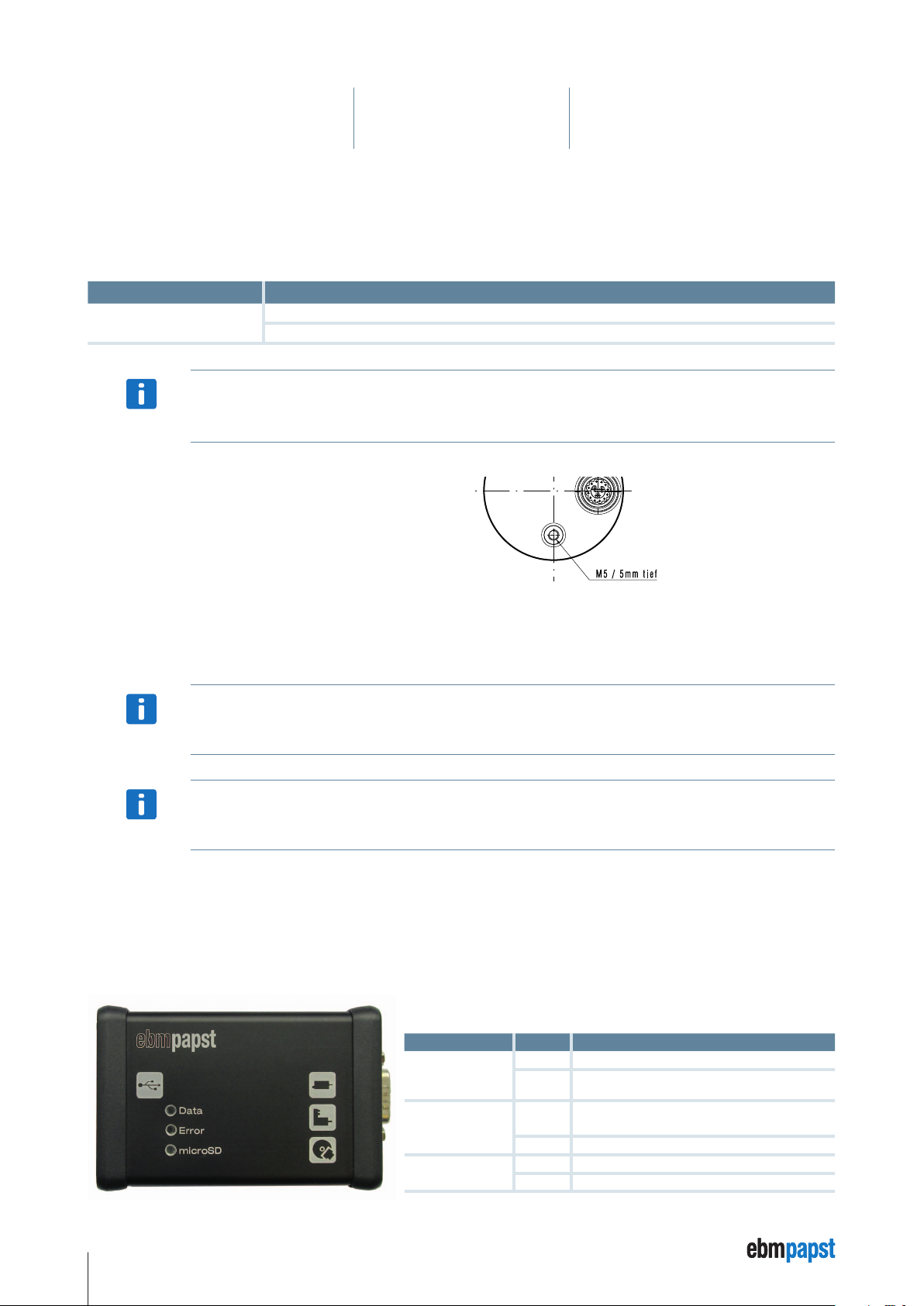
5.8 USB-CAN-RS485 adapter
The USB-CAN-RS485 adapter is required as an accessory for the ebm-papst “Kickstart” software, in order to connect the PC with the K4
drive. The adapter can be ordered under Material No. 914 0000 400.
Functional description of the LED displays
LED name Colour Function assignment
Data
Error
microSD
red • No assignment.
green
red
green • Received data is ok.
red • No assignment.
green • Access to the memory card.
• Active data transfer via the USB CAN-RS485
adapter.
• No response following request to K4.
• Receipt of a faulty data package.
26
Page 27

5 Installation
Pin assignment (D-SUB pin 9 pole):
Adapter electrically isolated
Pin Connection
1
2
3
4
5
6
7
8
9
USB device drivers of the type “FTDI USB Serial Converter” are required for operation of the USB-CAN-RS485 adapter. In many cases these
are already available on the PC or can be installed using the files provided in the subdirectory of the “Kickstart PC-Software\USB-CAN-basic-
driver-files”. Detailed installation instructions (in English) for the operating systems Windows 7, Windows Vista and Windows XP are provided
as PDF files in the installation directory of the “Kickstart” PC software.
n. c.
optional – CAN L bus cable
GND
RS485 +
n. c.
GND
optional – CAN H bus cable
RS485 –
n. c.
Scope of supply:
1 USB-CAN-RS485 adapter (incl. microSD memory card)
1 Screw terminal adapter board to the D-SUB 9 connection
1 USB connection cable to the PC.
5.9 Connection to the USB-CAN-RS485 adapter
• Connect the cable at Pin 10 (violet) with connection 4 (RS485 +) of the USB-CAN-RS485 adapter.
• Connect the cable at Pin 11 (grey/pink) with connection 8 (RS485 –) of the USB-CAN-RS485 adapter.
• Switch on the “Logic” voltage at the power supply unit.
• Start the “Kickstart” tool at the PC for parameterisation.
• Load an existing project (*.kickzip or *.kicktpl) or create a new project: *.kickpro.
27
Page 28
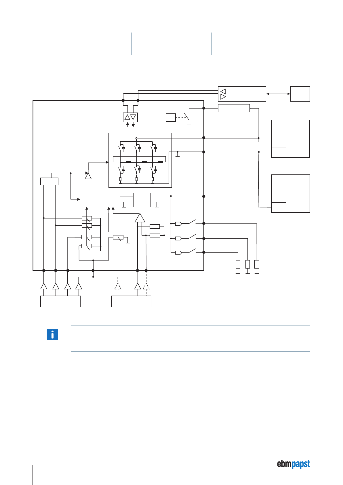
5.10 Circuit diagram
+
+
or
24 V (SPS)
ebmpapst
5 Installation
Motor VDC-3-49.15-K4
Motor ECI-63.XX-K4
Enable
IN 2
Control
LogicSMPS
RS485 -
RS485 +
U
Powerstage
GND
Analog IN 2
Ballast
µC
ZK
U
Logic
OUT 1
OUT 2
OUT 3*
RS485-Controller
Ballast - Resistor
Power Supply
„Power“
(+24 V / +48 V DC)
GND
Power Supply
„Logic“
(+24 V DC)
GND
Laptop
IN B
IN A
* The OUT 3 connection is only available for the ECI-63.XX-K4 drive systems.
IN 1
IN 2
The user is responsible for external fusing of the power supply.
NOTE
Analog IN 1 Analog GND
0…10 V
28
Page 29
5 Installation
SPS
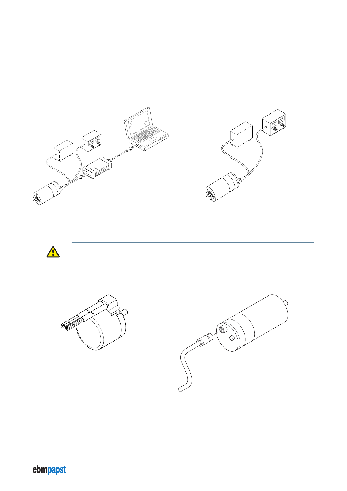
5.11 Schematic layout: parameterisation, commissioning (startup) and automatic operation
5.11.1 Parameterisation and commissioning 5.11.2 Automatic operation
Automatic operation with stored parameters and integrated control
Power supply
Control
SPS
USB-K4
ebmpapst
Data
Error
microSD
USB
microSD
Adapter
ECI-63.XX-K4 drive
5.11.3 Connecting connector at the motor
Risk of damage.
When plugging in the connector to the connection on the motor ECI-63.XX-K4, ensure that the company logo on the
CAUTION
connector is facing upwards towards the housing edge of the motor.
When connecting the Litz wires of the VDC-3-49.15-K4 motor variant, ensure that the pin assignment is precisely as
specified and not incorrectly assigned, as this causes irreparable damage to the motor electronics.
KICKSTART
Control
Power supply
PC with “Kick-
start” software
ECI-63.XX-K4 drive
VDC-3-49.15-K4
ECI-63.XX-K4
29
Page 30

6 Parameterisation
82 parameters are available for parameterising the VDC-3-49.15-K4 and ECI-63.XX-K4 drive systems (from page 32). These are managed
via the electronic class K4 and are set using the ebm-papst “Kickstart” PC software.
A detailed parameter description see Chapter “10 Parameter Description”, page 94.
6.1 Memory management
The K4 has a management function for the “RAM”, “custom” and “default” memory areas.
To edit the values you will need the password “custom access key”. This is set to 0 on delivery. If you change it, please ensure that it is not
lost.
6.1.1 “RAM” memory area
The motor operates with the values in the RAM area.
The memory class “appl func” can be changed (written) if the motor is at a standstill (IN A and IN B input to LOW). If the inputs are not set to
zero you will receive an error message in the status display.
The memory class “appl value” can be changed (written) while the motor is in operation and therefore directly affects the motor's perfor-
mance.
All values can be read out during operation or while the motor is at a standstill.
Parameters that are written in the “RAM” memory area with the “write” command are no longer available if the power supply fails or is
switched off.
6.1.2 “custom” memory area
To ensure that the data is available permanently, it must be located in the “custom” memory area. The data from the “RAM” area is not
written in the “custom” area unless the “store” command is used; after it has been moved the data is then permanently available. On
switching on the voltage, the data from the “custom” area is transferred into the “RAM” area.
30
Page 31

6 Parameterisation
6.1.3 “default” memory area
The default values loaded in the factory are stored in the “default” memory area. The operating data can be reset to the as-delivered
condition by using the “reload” command. The data is written in the “custom” and “RAM” areas.
Access to parameterisation with “customer access key” (password).
“Kickstart”
RS485
Drive memory area
external RAM custom default
reload
Parameter
(application
function)
Parameter
(application
value)
Parameter
(HW set val)
write
read power up reload
write
read power up reload
Parameter
(application
function)
Parameter
(application
value)
Parameter
(HW set val)
Parameter
(Offset single
sensor)
store
store
power up
power up
Parameter
(application
function)
reload
Parameter
(application
value)
Parameter
(HW set val)
Parameter
(Offset single
sensor)
Parameter
(application
function)
Parameter
(application
value)
Parameter
(HW set val)
Parameter
(Offset single
sensor)
Blue arrow = Command is executed in the operational status (clockwise, counterclockwise, braking / positioning)
Black arrow = Command is executed in the state unlock (motor in freewheel)
With the command „Save“, the „user access key“ is reseted.
The “store” command is used to reset the “customer access key”.
NOTE
31
Page 32

6 Parameterisation
6.2 Parameter
The following parameters are available in the K4:
For a detailed parameter description, see Chapter “10 Parameter Description”, page 94.
• The data in the “No. [dec]” column is relevant for the parameter descriptions, refer to Chapter “10 Parameter
Description”, from page 94.
NOTE
Parameterübersicht
Parameter
No. [hex]
0x1
0x2 Mode 2 1 8 appl func
0x3 O1 0 7 appl func
0x4 O2 0 7 appl func
0x5 O3 0 7 appl func
0x6 Restart 0 1 appl func
0x7 intentionally left blank 0 65535
0x8 intentionally left blank 0 65535
0x9 intentionally left blank 0 65535
0xA intentionally left blank 0 65535
0xB FE_Speed_X1 Digits 0 1023 appl func
0xC FE_Speed_X2 Digits 0 1023 appl func
0xD FE_Speed_X3 Digits 0 1023 appl func
0xE FE_Speed_X4 rpm –30000 29999 appl func
0xF FE_Speed_Y1 rpm –30000 29999 appl func
0x10 FE_Speed_Y2 rpm –30000 29999 appl func
0x11 FE_Speed_Y3 rpm –30000 29999 appl func
0x12 FE_Speed_Y4 rpm –30000 29999 appl func
0x13 Speed_X1_Hyst Digits 0 1023 appl func
0x14 Speed_X2_Hyst Digits 0 1023 appl func
0x15 Speed_X3_Hyst Digits 0 1023 appl func
0x16 Speed error rpm –30000 29999 appl func
0x17 Fixed speed N1 rpm –30000 29999 appl value
0x18 Fixed speed N2 rpm –30000 29999 appl value
0x19 Fixed speed N3 rpm –30000 29999 appl value
0x1A t ramp-up cw ms für 1000 rpm 0 65535 appl value
0x1B t ramp-down cw ms für 1000 rpm 0 65535 appl value
0x1C t ramp-up ccw ms für 1000 rpm 0 65535 appl value
0x1D t ram-down ccw ms für 1000 rpm 0 65535 appl value
0x1E Speed controller KP 0 65535 appl value
0x1F Speed controller KI 0 65535 appl value
• The data in the “No. [hex]” column is relevant for the “Kickstart” PC software.
• The data in column No. [hex] is the address of the parameter.
• The guide values for the parameters represent the so-called default parameters in the respective drive system.
Parameter
Name
Mode 1
Units min. max. Speicherklasse
1 9
appl func
32
Page 33

6 Parameterisation
Parameterübersicht
Parameter
No. [hex]
0x20
0x21 K_ff 1/255 0 65535 appl func
0x22 Actual speed averaging 2^x [ms] 0 15 appl value
0x23 Resolution of the actual outputs Pulse/mech.Umdrehung 0 100 appl value
0x24 Speed signal threshold rpm 0 29999 appl value
0x25 Speed signal delta hysteresis 0 29999 appl value
0x26 FE_Current_X1 Digits 0 1023 appl func
0x27 FE_Current_X2 Digits 0 1023 appl func
0x28 FE_Current_X3 Digits 0 1023 appl func
0x29 FE_Current_Y0 % 0 100 appl func
0x2A FE_Current_Y1 % 0 100 appl func
0x2B FE_Current_Y2 % 0 100 appl func
0x2C FE_Current_Y3 % 0 100 appl func
0x2D FE_Current_Y4 % 0 100 appl func
0x2E Current_X1_Hyst Digits 0 1023 appl func
0x2F Current_X2_Hyst Digits 0 1023 appl func
0x30 Current_X3_Hyst Digits 0 1023 appl func
0x31 Current error % 0 100 appl func
0x32 Current signal threshold 10 mA 0 32767 appl value
0x33 Current signal delta hysteresis 10 mA 0 65535 appl value
0x34 Current time constant ms 1 5000 appl value
0x35 Current gating time ms 0 5000 appl value
0x36 Reversing threshold 0 29999 appl value
0x37 Reversing threshold delta hysteresis rpm 0 29999 appl value
0x38 I_Max_driving_Rechts 10 mA 0 65535 appl value
0x39 I_Max_driving_Links 10 mA 0 65535 appl value
0x3A I_Max_braking_Rechts 10 mA 0 65535 appl value
0x3B I_Max_braking_Links 10 mA 0 65535 appl value
0x3C Hold gain KP_H 1/256 0 65535 appl value
0x3D PWM/Freq: Lower frequency limit Hz 25 15000 appl func
0x3E PWM/Freq: Upper frequency limit Hz 25 15000 appl func
0x3F Max. positioning speed rpm 0 29999 appl value
0x40 Coasting, cw 1/65535 revolutions 0 65535 appl value
0x41 Coasting, cw revolutions –32768 32767 appl value
0x42 Coasting ccw 1/65535 revolutions 0 65535 appl value
0x43 Coasting ccw revolutions 0–32768 32767 appl value
0x44 Distance 1/65535 revolutions 0 65535 appl value
0x45 Distance revolutions –32768 32767 appl value
0x46 Positive positioning window* 1/65535 revolutions 0 65535 appl value
0x47 Positive positioning window* revolutions 0 65535 appl value
0x48 Negative positioning window* 1/65535 revolutions 0 65535 appl value
Parameter
Name
Speed controller KD (currently unused)
* Parameter 46 + 47 (positive) = 1000
Parameter 48 + 49 (negativ) = 500
Target position = 50000
Here “Position reached” = ACTIVE should be set, if
Actual position > 49500 and actual position < 51000
Units min. max. Speicherklasse
0 65535
appl value
33
Page 34

6 Parameterisation
Parameterübersicht
Parameter
No. [hex]
0x49
0x4A U
0x4B U
0x4C U
0x4D Ballast chopper switching on threshold 10 mV 0 65535 appl value
0x4E Ballast chopper– switching off threshold 10 mV 0 65535 appl value
v4F Temperature signal threshold °C 0 110 appl value
0x50 Temperature signal delta hysteresis °C 0 110 appl value
0x51 Transmission ratio 1 65535 appl value
0x52 Bus address 1 127 appl value
0x8001 Current actual speed rpm appl value
0x8002 current electrical current, winding 10 mA appl value
0x8003 current actual position LoByte 1/65535 revolutions appl value
0x8004 current actual position HiByte revolutions appl value
0x8005 current actual temperature LP °C appl value
0x8006 current electrical current I
0x8007 current electrical current I
0x8008 Output status digital appl value
0x8009 Status of inputs: IN A, IN B, IN 1, IN digital appl value
0x800A not used
0x800B not used
0x800C not used
0x800D Analog IN 1 digits appl value
0x800E Analog IN 2 digits appl value
0x800F
Parameter
Name
Negative positioning window*
overvoltage threshold 10 mV 0 65535 appl value
ZK
undervoltage threshold 10 mV 0 65535 appl value
ZK
voltage hysteresis 10 mV 0 65535 appl value
ZK
d
q
Analog internal NTC
Units min. max. Speicherklasse
revolutions 0 65535
10 mA appl value
10 mA appl value
digits
appl value
appl value
34
Page 35

7 Parameterisation of the Operating Modes
The parameterisation of the operating modes is described in this chapter. 38 operating modes are available to choose from for the electronic
class K4. The operating modes are selected using parameters Mode 1 and Mode 2. The descriptions are laid out as follows:
7.1 Application example
Task: The motor should reach a fixed speed via a defined acceleration / braking ramp. If the speed has been reached a corre-
sponding display should appear.
Setpoint values:
Basic conditions:
After switching off: Brake motor / transition in free-wheeling? The motor should switch to free-wheeling.
Acceleration direction of rotation? Direction of rotation cw
Signal from a higher-level control? Yes. = 1 output (On / Off), 1 input (target speed reached signal).
Procedure:
Connect the electrical system (see Chapter 5.2 Installing the drive, page 22).
Start the “Kickstart” PC software at the PC.
1
Open project file
(File type .kicktpl / .kickzip)
Target speed n = 3500 rpm, acceleration time = 730 ms.
2
Enter user password
(Access Key “Customer” = “0”)
and confirm with “Set”.
35
Page 36

7 Parameterisation of the Operating Modes
3
• Operating mode selection:
Parameter O1h = 1, Parameter O2h = 1
• Speed signal O2 (OUT 2):
Parameter O4h = 2
4
• Fixed speed parameterisation:
Parameter 17h = 3500
• Parameterisation of
acceleration / braking (deceleration)
ramp:
Parameter 1ah, 1bh, 1ch, 1dh = 209 *
• Set speed signalling threshold: Parameter
24h = 3490
• Set signalling threshold hysteresis:
Parameter 25h = 40
* Determination of the acceleration value in ms
for 1000 rpm
Speed input: 3500 rpm, acceleration time: 730
ms
Acceleration value = acceleration
time / speed difference x 1000
730 / 3500 x 1000 = 208.57 ~ 209
5
Write parameters: Mark (select) the set
parameters and write in the RAM memory
area with the “Write” command.
36
Page 37

7 Parameterisation of the Operating Modes
6
Save parameters: Save the parameters
written with the “store” command in the
“custom” memory area.
Commissioning (startup)
The following connections must be set up for the commissioning:
UZK = supply voltage
GND = ground / earth
= supply voltage +24V
U
Logic
IN A= On / Off (see IN A / B logic table, see Chapter 8 Inputs and Outputs, page 77)
here: Switch from free-wheeling to rotational direction cw (speed control)
IN 1 = +24V (see logic table - fixed speeds)
here: Selection of N1
7.2 Parameterisation of the speed regulation characteristic
The speed regulation characteristic can be defined via three interpolation points. A hysteresis can be set for each interpolation point. In
addition, an error speed can be parameterised, which is used if an invalid X axis value results.
The speed regulation characteristic is defined using the following parameters:
P11 – FE_Speed_X1 P15 – FE_Speed_Y1 P19 – Speed_X1_Hyst
P12 – FE_Speed_X2 P16 – FE_Speed_Y2 P20 – Speed_X2_Hyst
P13 – FE_Speed_X3 P17 – FE_Speed_Y3 P21 – Speed_X3_Hyst
P14 – FE_Speed_Y0 P18 – FE_Speed_Y4 P22 – Error_Speed
37
Page 38

7 Parameterisation of the Operating Modes
X1 X2 X3
X1 X2 X3
The characteristic curve can then take on this shape:
Target velocity
Hysteresis 1
Hysteresis 2 Hysteresis 3
Y0
Y3
Y4
Y1 Y2
Normalised X axis
The speed values Y0…Y4 are given in rpm.
X values: Target value analog IN A1: 0 – 10 V corresponds 0 – 1023.
Target value PWM IN 1: 0 – 100 % corresponds X value 0 – 100.
Target value frequency IN 1: lower cut-off frequency (Parameter 0x3D) corresponds X value 0.
Target value frequency IN 1: upper cut-off frequency (Paramete r 0x3E) corresponds X value 1023.
7.3 Parameterisation of the maximum current characteristic
The maximum current characteristic can be defined via three interpolation points. A hysteresis can be set for each interpolation point. In
addition, an error current can be parameterised, which is used if an invalid X axis value results.
The maximum current characteristic is defined using the following parameters:
P11 – FE_Current_X1 P15 – FE_Current_Y1 P19 – Current_X1_Hyst
P12 – FE_Current_X2 P16 – FE_Current_Y2 P20 – Current_X2_Hyst
P13 – FE_Current_X3 P17 – FE_Current_Y3 P21 – Current_X3_Hyst
P14 – FE_Current_Y0 P18 – FE_Current_Y4 P22 – Error_Current
The characteristic curve can then take on this shape:
Target current
Hysteresis 1
Hysteresis 2
Hysteresis 3
Y0
Y3
Y4
Y1 Y2
Normalised X axis
38
Page 39

7 Parameterisation of the Operating Modes
The current limitation is defined via parameters 0x38 - 0x3B. The values of the parameters 0x38 - 0x3B must be the
same if the maximum current characteristic is used. If the operational quadrants are changed there are no jumps in the
NOTE
The speed values Y0…Y4 are given in %.
X values: Target value analog IN A1: 0 – 10 V corresponds 0 – 1023.
Target value PWM IN 1: 0 – 100 % corresponds X value 0 – 100.
Target value frequency IN 1: lower cut-off frequency (Parameter 0x3D) corresponds X value 0.
Target value frequency IN 1: upper cut-off frequency (Paramete r 0x3E) corresponds X value 1023.
These are defined via:
P 38 – I_Max_driving_rh
P 39 – I_Max_driving_lh
P 3A – I_Max_braking_rh
P 3B – I_Max_braking_lh
current limitation.
39
Page 40

7 Parameterisation of the Operating Modes
7.4 Operating mode 11: Speed setpoint N1, N2, N3; Analog IN 1
The following example is used to describe operating mode 11 in greater detail.
In order for the parameter to function, KP_H must be > 0.
NOTE
Parameter No.1 (Mode 1) has value = 1
Parameter No.2 (Mode 2) has value = 1
With input circuit IN A = 0 and IN B = 0 the motor is in free-wheeling (free running) state and the inputs IN 1 and IN 2 have no effect.
With input circuit IN A = 1 and IN B = 0 the motor rotates in a positive (clockwise - cw) direction. If the inputs are IN 1 = 0 and IN 2 = 0, the
analog value of analog IN 1 is used and the speed depends on this value.
With input circuit IN A = 1 and IN B = 0 the motor rotates in a positive (clockwise - cw) direction. If the inputs are IN 1 = 1 and IN 2 = 0, the
speed is controlled to the value that given in N1.
Function IN 1: Selection of the speed setpoint source analog / parameter.
Function IN 2: Selection of the speed setpoint source analog / parameter.
Speed Current limit
IN A IN B IN 1 IN 2 Direction Value Type Value Function Comment
0 0 x x - 0 - - Free-wheeling No braking, no current feed
1 0 0 0 pos A1 S P N control
1 0 1 0 pos N1 S P N control
1 0 0 1 pos N2 S P N control
1 0 1 1 pos N3 S P N control
0 1 0 0 neg A1 S P N control
0 1 1 0 neg N1 S P N control
0 1 0 1 neg N2 S P N control
0 1 1 1 neg N3 S P N control
1 1 0 0 - 0 S P Stop Braking and stopping
1 1 1 0 - 0 S P Stop Braking and stopping
1 1 0 1 - 0 S P Stop Braking and stopping
1 1 1 1 - 0 S P Stop Braking and stopping
Stop control = If KP_H > 0; brake and stop in the current position on changeover to IN A = IN B = 1 + Coasting rh, lh.
If KP_H = 0; brake and stop on changeover to IN A = IN B = 1, run speed to 0.
S = Static
P = Parameter
F = Freeze
D = Dynamic
x = Arbitrary value
40
Page 41

7 Parameterisation of the Operating Modes
7.5 Operating mode 12: Speed setpoints N1, A1; dynamic current limitation via A1
In order for the parameter to function, KP_H must be > 0.
NOTE
Function IN 1: Selection of the speed setpoint source analog A1 / parameter N1.
Function IN 2: selection of static / dynamic current limitation.
Speed Current limit
IN A IN B IN 1 IN 2 Direction Type Value Type Value Function Comment
0 0 x x - 0 - - Free-wheeling No braking, no current feed
1 0 0 0 pos D A1 F A1 N control
1 0 1 0 pos P N1 F A1 N control
1 0 0 1 pos F A1 D A1 N control
1 0 1 1 pos P N1 D A1 N control
0 1 0 0 neg D A1 F A1 N control
0 1 1 0 neg P N1 F A1 N control
0 1 0 1 neg F A1 D A1 N control
0 1 1 1 neg P N1 D A1 N control
1 1 0 0 - 0 F A1 Stop Braking and stopping
1 1 1 0 - 0 F A1 Stop Braking and stopping
1 1 0 1 - 0 D A1 Stop Braking and stopping
1 1 1 1 - 0 D A1 Stop Braking and stopping
Stop control = If KP_H > 0; brake and stop in the current position on changeover to IN A = IN B = 1 + Coasting
rh, lh.
If KP_H = 0; brake and stop on changeover to IN A = IN B = 1, run speed to 0.
Initialisation static current limit = I_max parameter 0x38, 0x39, 0x3A, 0x3B
Initialisation speed setpoint = 0
S = Static
P = Parameter
F = Freeze; on level changeover to IN 2 the current level is frozen (Saved) at A1)
D = Dynamic
x = Arbitrary value
41
Page 42

7 Parameterisation of the Operating Modes
7.6 Operating mode 13: Speed setpoints A1, N1; distance
In order for the parameter to function, KP_H must be > 0.
NOTE
Function IN 1: Selection of the speed setpoint source analog A1 / parameter N1.
Function IN 2: Travel distance; the distance increases with each high flank (x); displacement = x*distance.
Speed Current limit
IN A IN B IN 1 IN 2 Direction Value Type Value Function Comment
0 0 x x - 0 - - Free-wheeling No braking, no current feed
1 0 0 x pos A1 S P N control
1 0 1 x pos N1 S P N control
1 0 0 x pos A1 S P N control
1 0 1 x pos N1 S P N control
0 1 0 x neg A1 S P N control
0 1 1 x neg N1 S P N control
0 1 0 x neg A1 S P N control
0 1 1 x neg N1 S P N control
1 1 0 0 - 0 S P Stop Stopping
1 1 1 0 - 0 S P Stop Stopping
1 1 0 0 -> 1 - A1 S P Distance Positioning
1 1 1 0 -> 1 - N1 S P Distance Positioning
Distance = Parameter 44 + 45; relative distance with plus/minus sign. Positive distances are travelled in a clockwise direction.
Travel distance only if KP_H > 0
For further information, see page 33.
Stop control = If KP_H > 0; brake and stop in the current position on changeover to IN A = IN B = 1 + Coasting rh, lh.
If KP_H = 0; brake and stop on changeover to IN A = IN B = 1, run speed to 0.
S = Static
P = Parameter
F = Freeze
D = Dynamic
x = Arbitrary value
42
Page 43

7 Parameterisation of the Operating Modes
7.7 Operating mode 16: Speed setpoints A1, N1; rotational direction
In order for the parameter to function, KP_H must be > 0.
NOTE
Function IN 1: Selection of the speed setpoint source analog A1 / parameter N1.
Function IN 2: Selecting the rotational direction.
Speed Current limit
IN A IN B IN 1 IN 2 Direction Value Type Value Function Comment
0 0 x x - 0 - - Free-wheeling No braking, no current feed
1 0 0 0 pos A1 S P N control
1 0 1 0 pos N1 S P N control
1 0 0 1 neg A1 S P N control
1 0 1 1 neg N1 S P N control
0 1 0 0 neg A1 S P N control
0 1 1 0 neg N1 S P N control
0 1 0 1 pos A1 S P N control
0 1 1 1 pos N1 S P N control
1 1 0 0 - 0 S P Stop Braking and stopping
1 1 1 0 - 0 S P Stop Braking and stopping
1 1 0 1 - 0 S P Stop Braking and stopping
1 1 1 1 - 0 S P Stop Braking and stopping
Stop control = If KP_H > 0; brake and stop in the current position on changeover to IN A = IN B = 1 + Coasting rh, lh.
If KP_H = 0; brake and stop on changeover to IN A = IN B = 1, run speed to 0.
S = Static
P = Parameter
F = Freeze
D = Dynamic
x = Arbitrary value
43
Page 44

7 Parameterisation of the Operating Modes
7.8 Operating mode 17: Speed setpoints A1, N1; dynamic current limit via A2
In order for the parameter to function, KP_H must be > 0.
NOTE
Function IN 1: Selection of the speed setpoint source analog A1 / parameter N1.
Function IN 2: Analog A2 dynamic current limitation.
Speed Current limit
IN A IN B IN 1 IN 2 Direction Value Type Value Function Comment
0 0 x A2 - 0 - - Free-wheeling No braking, no current feed
1 0 0 A2 pos A1 D A2 N control
1 0 1 A2 pos N1 D A2 N control
1 0 0 A2 pos A1 D A2 N control
1 0 1 A2 pos N1 D A2 N control
0 1 0 A2 neg A1 D A2 N control
0 1 1 A2 neg N1 D A2 N control
0 1 0 A2 neg A1 D A2 N control
0 1 1 A2 neg N1 D A2 N control
1 1 0 A2 - 0 D A2 Stop Braking and stopping
1 1 1 A2 - 0 D A2 Stop Braking and stopping
1 1 0 A2 - 0 D A2 Stop Braking and stopping
1 1 1 A2 - 0 D A2 Stop Braking and stopping
Stop control = If KP_H > 0; brake and stop in the current position on changeover to IN A = IN B = 1 + Coasting rh, lh.
If KP_H = 0; brake and stop on changeover to IN A = IN B = 1, run speed to 0.
S = Static
P = Parameter
F = Freeze
D = Dynamic
x = Arbitrary value
44
Page 45

7 Parameterisation of the Operating Modes
7.9 Operating mode 18: Speed setpoints A1, N1; brake
In order for the parameter to function, KP_H must be > 0.
NOTE
Function IN 1: Selection of the speed setpoint source analog A1 / parameter N1.
Function IN 2: Input for braking voltage; motor only runs if brake released.
Speed Current limit
IN A IN B IN 1 IN 2 Direction Value Type Value Function Comment
0 0 x x - 0 - - Free-wheeling No current feed
1 0 0 0 - 0 S P Free-wheeling
1 0 1 0 - 0 S P Free-wheeling
1 0 0 1 pos A1 S P N control
1 0 1 1 pos N1 S P N control
0 1 0 0 - 0 S P Free-wheeling
0 1 1 0 - 0 S P Free-wheeling
0 1 0 1 neg A1 S P N control
0 1 1 1 neg N1 S P N control
1 1 0 0 - 0 S P Free-wheeling
1 1 1 0 - 0 S P Free-wheeling
1 1 0 1 - 0 S P Stop Stopping
1 1 1 1 - 0 S P Stop Stopping
Stop control = If KP_H > 0; brake and stop in the current position on changeover to IN A = IN B = 1 + Coasting rh, lh.
If KP_H = 0; brake and stop on changeover to IN A = IN B = 1, run speed to 0.
S = Static
P = Parameter
F = Freeze
D = Dynamic
x = Arbitrary value
45
Page 46

7 Parameterisation of the Operating Modes
7.10 Operating mode 21: dynamic current limit via A1; speed setpoints A1, N2
In order for the parameter to function, KP_H must be > 0.
NOTE
Function IN 1: selection of static / dynamic current limitation.
Function IN 2: Selection of the speed setpoint source analog A1 / parameter N2.
Speed Current limit
IN A IN B IN 1 IN 2 Direction Type Value Type Value Function Comment
0 0 x x - 0 - - Free-wheeling No braking, no current feed
1 0 0 0 pos D A1 F A1 N control
1 0 1 0 pos F A1 D A1 N control
1 0 0 1 pos P N2 F A1 N control
1 0 1 1 pos P N2 D A1 N control
0 1 0 0 neg D A1 F A1 N control
0 1 1 0 neg F A1 D A1 N control
0 1 0 1 neg P N2 F A1 N control
0 1 1 1 neg P N2 D A1 N control
1 1 0 0 - 0 F A1 Stop Braking and stopping
1 1 1 0 - 0 D A1 Stop Braking and stopping
1 1 0 1 - 0 F A1 Stop Braking and stopping
1 1 1 1 - 0 D A1 Stop Braking and stopping
Stop control = If KP_H > 0; brake and stop in the current position on changeover to IN A = IN B = 1 + Coasting
rh, lh.
If KP_H = 0; brake and stop on changeover to IN A = IN B = 1, run speed to 0.
Initialisation static current limit = I_max parameter 0x38, 0x39, 0x3A, 0x3B
Initialisation speed setpoint = 0
S = Static
P = Parameter
F = Freeze; on level changeover to IN 1 the current level is frozen (saved) at A1.
D = Dynamic
x = Arbitrary value
46
Page 47

7 Parameterisation of the Operating Modes
7.11 Operating mode 23: dynamic current limit via A1; distance
In order for the parameter to function, KP_H must be > 0.
NOTE
Function IN 1: selection of static / dynamic current limitation.
Function IN 2: Travel distance; the distance increases with each high flank (x); displacement = x*distance.
Speed Current limit
IN A IN B IN 1 IN 2 Direction Type Value Type Value Function Comment
0 0 x x - 0 - - Free-wheeling No braking, no current feed
1 0 0 x pos D A1 F A1 N control
1 0 1 x pos F A1 D A1 N control
1 0 0 x pos D A1 F A1 N control
1 0 1 x pos F A1 D A1 N control
0 1 0 x neg D A1 F A1 N control
0 1 1 x neg F A1 D A1 N control
0 1 0 x neg D A1 F A1 N control
0 1 1 x neg F A1 D A1 N control
1 1 0 0 - 0 F A1 Stop Stopping
1 1 1 0 - 0 D A1 Stop Stopping
1 1 0 0 -> 1 - D A1 F A1 Distance Positioning
1 1 1 0 -> 1 - F A1 D A1 Distance Positioning
Distance = Parameter 44 + 45; relative distance with plus/minus sign. Positive distances are travelled in a
clockwise direction.
Travel distance only if KP_H > 0
For further information, see page 33.
Stop control = If KP_H > 0; brake and stop in the current position on changeover to IN A = IN B = 1 + Coasting
rh, lh.
If KP_H = 0; brake and stop on changeover to IN A = IN B = 1, run speed to 0.
Initialisation static current limit = I_max parameter 0x38, 0x39, 0x3A, 0x3B
Initialisation speed setpoint = 0
S = Static
P = Parameter
F = Freeze; on level changeover to IN 1 the current level is frozen (saved) at A1.
D = Dynamic
x = Arbitrary value
47
Page 48

7 Parameterisation of the Operating Modes
7.12 Operating mode 26: dynamic current limit via A1; rotational direction
In order for the parameter to function, KP_H must be > 0.
NOTE
Function IN 1: selection of static / dynamic current limitation.
Function IN 2: Selecting the rotational direction.
Speed Current limit
IN A IN B IN 1 IN 2 Direction Type Value Type Value Function Comment
0 0 x x - 0 - - Free-wheeling No braking, no current feed
1 0 0 0 pos D A1 F A1 N control
1 0 1 0 pos F A1 D A1 N control
1 0 0 1 neg D A1 F A1 N control
1 0 1 1 neg F A1 D A1 N control
0 1 0 0 neg D A1 F A1 N control
0 1 1 0 neg F A1 D A1 N control
0 1 0 1 pos D A1 F A1 N control
0 1 1 1 pos F A1 D A1 N control
1 1 0 0 - 0 F A1 Stop Braking and stopping
1 1 1 0 - 0 D A1 Stop Braking and stopping
1 1 0 1 - 0 F A1 Stop Braking and stopping
1 1 1 1 - 0 D A1 Stop Braking and stopping
Stop control = If KP_H > 0; brake and stop in the current position on changeover to IN A = IN B = 1 + Coasting
rh, lh.
If KP_H = 0; brake and stop on changeover to IN A = IN B = 1, run speed to 0.
Initialisation static current limit = I_max parameter 0x38, 0x39, 0x3A, 0x3B
Initialisation speed setpoint = 0
S = Static
P = Parameter
F = Freeze; on level changeover to IN 1 the current level is frozen (saved) at A1.
D = Dynamic
x = Arbitrary value
48
Page 49

7 Parameterisation of the Operating Modes
7.13 Operating mode 28: dynamic current limit via A1; brake
In order for the parameter to function, KP_H must be > 0.
NOTE
Function IN 1: selection of static / dynamic current limitation.
Function IN 2: Input for braking voltage; motor only runs if brake released.
Speed Current limit
IN A IN B IN 1 IN 2 Direction Type Value Type Value Function Comment
0 0 x x - 0 - - Free-wheeling No current feed
1 0 0 0 - D A1 F A1 Free-wheeling
1 0 1 0 - F A1 D A1 Free-wheeling
1 0 0 1 pos D A1 F A1 N control
1 0 1 1 pos F A1 D A1 N control
0 1 0 0 - D A1 F A1 Free-wheeling
0 1 1 0 - F A1 D A1 Free-wheeling
0 1 0 1 neg D A1 F A1 N control
0 1 1 1 neg F A1 D A1 N control
1 1 0 0 - 0 F A1 Free-wheeling
1 1 1 0 - 0 D A1 Free-wheeling
1 1 0 1 - 0 F A1 Stop Stopping
1 1 1 1 - 0 D A1 Stop Stopping
IN 2 = 0; Brake closed
IN 2 = 1; Brake open
NOTE
Stop control = If KP_H > 0; brake and stop in the current position on changeover to IN A = IN B = 1 + Coasting
rh, lh.
If KP_H = 0; brake and stop on changeover to IN A = IN B = 1, run speed to 0.
Initialisation static current limit = I_max parameter 0x38, 0x39, 0x3A, 0x3B
Initialisation speed setpoint = 0
S = Static
P = Parameter
F = Freeze; on level changeover to IN 1 the current level is frozen (saved) at A1.
D = Dynamic
x = Arbitrary value
49
Page 50

7 Parameterisation of the Operating Modes
7.14 Operating mode 31: Distance; speed setpoints A1, N2
In order for the parameter to function, KP_H must be > 0.
NOTE
Function IN 1: Travel distance; the distance increases with each high flank (x); displacement = x*distance.
Function IN 2: Selection of the speed setpoint source analog A1 / parameter N2.
Speed Current limit
IN A IN B IN 1 IN 2 Direction Value Type Value Function Comment
0 0 x x - 0 - - Free-wheeling No braking, no current feed
1 0 x 0 pos A1 S P N control
1 0 x 0 pos A1 S P N control
1 0 x 1 pos N2 S P N control
1 0 x 1 pos N2 S P N control
0 1 x 0 neg A1 S P N control
0 1 x 0 neg A1 S P N control
0 1 x 1 neg N2 S P N control
0 1 x 1 neg N2 S P N control
1 1 0 0 - 0 S P Stop Stopping
1 1 0 -> 1 0 - A1 S P Distance Positioning
1 1 0 1 - 0 S P Stop Stopping
1 1 0 -> 1 1 - N2 S P Distance Positioning
Distance = Parameter 44 + 45; relative distance with plus/minus sign. Positive distances are travelled in a clockwise direction.
Travel distance only if KP_H > 0
For further information, see page 33.
Stop control = If KP_H > 0; brake and stop in the current position on changeover to IN A = IN B = 1 + Coasting rh, lh.
If KP_H = 0; brake and stop on changeover to IN A = IN B = 1, run speed to 0.
S = Static
P = Parameter
F = Freeze
D = Dynamic
x = Arbitrary value
50
Page 51

7 Parameterisation of the Operating Modes
7.15 Operating mode 32: Distance; dynamic current limit via A1
In order for the parameter to function, KP_H must be > 0.
NOTE
Function IN 1: Travel distance; the distance increases with each high flank (x); displacement = x*distance.
Function IN 2: selection of static / dynamic current limitation.
Speed Current limit
IN A IN B IN 1 IN 2 Direction Type Value Type Value Function Comment
0 0 x x - 0 - - Free-wheeling No braking, no current feed
1 0 x 0 pos D A1 F A1 N control
1 0 x 0 pos D A1 F A1 N control
1 0 x 1 pos F A1 D A1 N control
1 0 x 1 pos F A1 D A1 N control
0 1 x 0 neg D A1 F A1 N control
0 1 x 0 neg D A1 F A1 N control
0 1 x 1 neg F A1 D A1 N control
0 1 x 1 neg F A1 D A1 N control
1 1 0 0 - 0 F A1 Stop Stopping
1 1 0 -> 1 0 - D A1 F A1 Distance Positioning
1 1 0 1 - 0 D A1 Stop Stopping
1 1 0 -> 1 1 - F A1 D A1 Distance Positioning
Distance = Parameter 44 + 45; relative distance with plus/minus sign. Positive distances are travelled in a
clockwise direction.
Travel distance only if KP_H > 0
For further information, see page 33.
Stop control = If KP_H > 0; brake and stop in the current position on changeover to IN A = IN B = 1 + Coasting
rh, lh.
If KP_H = 0; brake and stop on changeover to IN A = IN B = 1, run speed to 0.
Initialisation static current limit = I_max parameter 0x38, 0x39, 0x3A, 0x3B
Initialisation speed setpoint = 0
S = Static
P = Parameter
F = Freeze; on level changeover to IN 2 the current level is frozen (Saved) at A1.
D = Dynamic
x = Arbitrary value
51
Page 52

7 Parameterisation of the Operating Modes
7.16 Operating mode 34: Distance; teach
In order for the parameter to function, KP_H must be > 0.
NOTE
Function IN 1: Travel distance; the distance increases with each high flank (x); displacement = x*distance.
Function IN 2: Learn a displacement; difference in position between teach start and each stop;
Save in distance = parameter 68 + 69.
Speed Current limit
IN A IN B IN 1 IN 2 Direction Value Type Value Function Comment
0 0 x 0 - 0 - - Free-wheeling
0 0 x 1 - 0 - - Free-wheeling
1 0 x 0 pos A1 S P N control Teach stop
1 0 x 1 pos A1 S P N control Teach start
1 0 x 0 pos A1 S P N control Teach stop
1 0 x 1 pos A1 S P N control Teach start
0 1 x 0 neg A1 S P N control Teach stop
0 1 x 1 neg A1 S P N control Teach start
0 1 x 0 neg A1 S P N control Teach stop
0 1 x 1 neg A1 S P N control Teach start
1 1 0 0 - 0 S P Stop Stopping
1 1 0 -> 1 0 - A1 S P Distance Positioning
1 1 0 1 - 0 S P Stop Stopping
1 1 0 -> 1 1 - A1 S P Distance Positioning
No braking, no current feed,
Teach stop
No braking, no current feed,
Teach start
Distance = Parameter 44 + 45; relative distance with plus/minus sign. Positive distances are travelled in a clockwise direction.
Travel distance only if KP_H > 0
For further information, see page 33.
Stop control = If KP_H > 0; brake and stop in the current position on changeover to IN A = IN B = 1 + Coasting rh, lh.
If KP_H = 0; brake and stop on changeover to IN A = IN B = 1, run speed to 0.
S = Static
P = Parameter
F = Freeze
D = Dynamic
x = Arbitrary value
52
Page 53

7 Parameterisation of the Operating Modes
7.17 Operating mode 36: Distance; rotational direction
In order for the parameter to function, KP_H must be > 0.
NOTE
Function IN 1: Travel distance; the distance increases with each high flank (x); displacement = x*distance.
Function IN 2: Selecting the rotational direction.
Speed Current limit
IN A IN B IN 1 IN 2 Direction Value Type Value Function Comment
0 0 x x - 0 - - Free-wheeling No braking, no current feed
1 0 x 0 pos A1 S P N control
1 0 x 0 pos A1 S P N control
1 0 x 1 neg A1 S P N control
1 0 x 1 neg A1 S P N control
0 1 x 0 neg A1 S P N control
0 1 x 0 neg A1 S P N control
0 1 x 1 pos A1 S P N control
0 1 x 1 pos A1 S P N control
1 1 0 0 - 0 S P Stop Stopping
1 1 0 -> 1 0 - A1 S P Distance Positioning
1 1 0 1 - 0 S P Stop Stopping
1 1 0 -> 1 1 - A1 S P Distance Positioning
1 1 0 -> 1 1 - A1 S P Distance Positioning
Distance = Parameter 44 + 45; relative distance with plus/minus sign. Positive distances are travelled in a clockwise direction.
Travel distance only if KP_H > 0
For further information, see page 33.
Stop control = If KP_H > 0; brake and stop in the current position on changeover to IN A = IN B = 1 + Coasting rh, lh.
If KP_H = 0; brake and stop on changeover to IN A = IN B = 1, run speed to 0.
S = Static
P = Parameter
F = Freeze
D = Dynamic
x = Arbitrary value
53
Page 54

7 Parameterisation of the Operating Modes
7.18 Operating mode 37: Distance; dynamic current limit A2
In order for the parameter to function, KP_H must be > 0.
NOTE
Function IN 1: Travel distance; the distance increases with each high flank (x); displacement = x*distance.
Function IN 2: Analog A2 dynamic current limitation.
Speed Current limit
IN A IN B IN 1 IN 2 Direction Value Type Value Function Comment
0 0 x A2 - 0 - - Free-wheeling No braking, no current feed
1 0 x A2 pos A1 D A2 N control
1 0 x A2 pos A1 D A2 N control
1 0 x A2 pos A1 D A2 N control
1 0 x A2 pos A1 D A2 N control
0 1 x A2 neg A1 D A2 N control
0 1 x A2 neg A1 D A2 N control
0 1 x A2 neg A1 D A2 N control
0 1 x A2 neg A1 D A2 N control
1 1 0 A2 - 0 D A2 Stop Stopping
1 1 0 -> 1 A2 - A1 D A2 Distance Positioning
1 1 0 A2 - 0 D A2 Stop Stopping
1 1 0 -> 1 A2 - A1 D A2 Distance Positioning
Distance = Parameter 44 + 45; relative distance with plus/minus sign. Positive distances are travelled in a clockwise direction.
Travel distance only if KP_H > 0
For further information, see page 33.
Stop control = If KP_H > 0; brake and stop in the current position on changeover to IN A = IN B = 1 + Coasting rh, lh.
If KP_H = 0; brake and stop on changeover to IN A = IN B = 1, run speed to 0.
S = Static
P = Parameter
F = Freeze
D = Dynamic
x = Arbitrary value
54
Page 55

7 Parameterisation of the Operating Modes
7.19 Operating mode 38: Distance; brake
In order for the parameter to function, KP_H must be > 0.
NOTE
Function IN 1: Travel distance; the distance increases with each high flank (x); displacement = x*distance.
Function IN 2: Input for braking voltage; motor only runs if brake released.
Speed Current limit
IN A IN B IN 1 IN 2 Direction Value Type Value Function Comment
0 0 x x - 0 - - Free-wheeling No current feed
1 0 x 0 - 0 S P Free-wheeling
1 0 x 0 - 0 S P Free-wheeling
1 0 x 1 pos A1 S P N control
1 0 x 1 pos A1 S P N control
0 1 x 0 - 0 S P Free-wheeling
0 1 x 0 - 0 S P Free-wheeling
0 1 x 1 neg A1 S P N control
0 1 x 1 neg A1 S P N control
1 1 0 0 - 0 S P Free-wheeling
1 1 0 -> 1 0 - 0 S P Free-wheeling
1 1 0 1 - 0 S P Stop Stopping
1 1 0 -> 1 1 - A1 S P Distance Positioning
IN 2 = 0; brake closed
IN 2 = 1; brake open
NOTE
Distance = Parameter 44 + 45; relative distance with plus/minus sign. Positive distances are travelled in a clockwise direction.
Travel distance only if KP_H > 0
For further information, see page 33.
Stop control = If KP_H > 0; brake and stop in the current position on changeover to IN A = IN B = 1 + Coasting rh, lh.
If KP_H = 0; brake and stop on changeover to IN A = IN B = 1, run speed to 0.
S = Static
P = Parameter
F = Freeze
D = Dynamic
x = Arbitrary value
55
Page 56

7 Parameterisation of the Operating Modes
7.20 Operating mode 43: Teach; distance
In order for the parameter to function, KP_H must be > 0.
NOTE
Function IN 1: Learn a displacement; difference in position between teach start and each stop;
Save in distance = parameter 68 + 69.
Function IN 2: Travel distance; the distance increases with each high flank (x); displacement = x*distance.
Speed Current limit
IN A IN B IN 1 IN 2 Direction Value Type Value Function Comment
0 0 0 x - 0 - - Free-wheeling
0 0 1 x - 0 - - Free-wheeling
1 0 0 x pos A1 S P N control Teach stop
1 0 1 x pos A1 S P N control Teach start
1 0 0 x pos A1 S P N control Teach stop
1 0 1 x pos A1 S P N control Teach start
0 1 0 x neg A1 S P N control Teach stop
0 1 1 x neg A1 S P N control Teach start
0 1 0 x neg A1 S P N control Teach stop
0 1 1 x neg A1 S P N control Teach start
1 1 0 0 - 0 S P Stop Stopping
1 1 1 0 - 0 S P Stop Stopping
1 1 0 0 -> 1 - A1 S P Distance Positioning
1 1 1 0 -> 1 - A1 S P Distance Positioning
No braking, no current feed,
teach stop
No braking, no current feed,
teach start
Distance = Parameter 44 + 45; relative distance with plus/minus sign. Positive distances are travelled in a clockwise direction.
Travel distance only if KP_H > 0
For further information, see page 33.
Stop control = If KP_H > 0; brake and stop in the current position on changeover to IN A = IN B = 1 + Coasting rh, lh.
If KP_H = 0; brake and stop on changeover to IN A = IN B = 1, run speed to 0.
S = Static
P = Parameter
F = Freeze
D = Dynamic
x = Arbitrary value
56
Page 57

7 Parameterisation of the Operating Modes
7.21 Operating mode 55: IN A / B logic via IN 1, IN 2; IN A / IN B as release (enable)
In order for the parameter to function, KP_H must be > 0.
NOTE
Function IN 1: Emulation IN A.
Function IN 2: Emulation IN B.
Speed Current limit
IN A IN B IN 1 IN 2 Direction Value Type Value Function Comment
0 0 x x - 0 - - Free-wheeling No braking, no current feed
1 0 0 0 - 0 S P Free-wheeling No braking, no current feed
1 0 1 0 pos A1 S P N control
1 0 0 1 neg A1 S P N control
1 0 1 1 - 0 S P Stop Braking and stopping
0 1 0 0 - 0 S P Free-wheeling No braking, no current feed
0 1 1 0 pos A1 S P N control
0 1 0 1 neg A1 S P N control
0 1 1 1 - 0 S P Stop Braking and stopping
1 1 0 0 - 0 S P Free-wheeling No braking, no current feed
1 1 1 0 pos A1 S P N control
1 1 0 1 neg A1 S P N control
1 1 1 1 - 0 S P Stop Braking and stopping
Stop control = If KP_H > 0; brake and stop in the current position on changeover to IN A = IN B = 1 + Coasting rh, lh.
If KP_H = 0; brake and stop on changeover to IN A = IN B = 1, run speed to 0.
S = Static
P = Parameter
F = Freeze
D = Dynamic
x = Arbitrary value
57
Page 58
7 Parameterisation of the Operating Modes
7.22 Operating mode 61: Rotational direction; speed setpoints A1, N2
In order for the parameter to function, KP_H must be > 0.
NOTE
Function IN 1: Selecting the rotational direction.
Function IN 2: Selection of the speed setpoint source analog A1 / parameter N2.
Speed Current limit
IN A IN B IN 1 IN 2 Direction Value Type Value Function Comment
0 0 x x - 0 - - Free-wheeling No braking, no current feed
1 0 0 0 pos A1 S P N control
1 0 1 0 neg A1 S P N control
1 0 0 1 pos N2 S P N control
1 0 1 1 neg N2 S P N control
0 1 0 0 neg A1 S P N control
0 1 1 0 pos A1 S P N control
0 1 0 1 neg N2 S P N control
0 1 1 1 pos N2 S P N control
1 1 0 0 - 0 S P Stop Braking and stopping
1 1 1 0 - 0 S P Stop Braking and stopping
1 1 0 1 - 0 S P Stop Braking and stopping
1 1 1 1 - 0 S P Stop Braking and stopping
Stop control = If KP_H > 0; brake and stop in the current position on changeover to IN A = IN B = 1 + Coasting rh, lh.
If KP_H = 0; brake and stop on changeover to IN A = IN B = 1, run speed to 0.
S = Static
P = Parameter
F = Freeze
D = Dynamic
x = Arbitrary value
58
Page 59

7 Parameterisation of the Operating Modes
7.23 Operating mode 62: Rotational direction; dynamic current limit via A1
In order for the parameter to function, KP_H must be > 0.
NOTE
Function IN 1: Selecting the rotational direction.
Function IN 2: selection of static / dynamic current limitation.
Speed Current limit
IN A IN B IN 1 IN 2 Direction Type Value Type Value Function Comment
0 0 x x - 0 - - Free-wheeling No braking, no current feed
1 0 0 0 pos D A1 F A1 N control
1 0 1 0 neg D A1 F A1 N control
1 0 0 1 pos F A1 D A1 N control
1 0 1 1 neg F A1 D A1 N control
0 1 0 0 neg D A1 F A1 N control
0 1 1 0 pos D A1 F A1 N control
0 1 0 1 neg F A1 D A1 N control
0 1 1 1 pos F A1 D A1 N control
1 1 0 0 - 0 F A1 Stop Braking and stopping
1 1 1 0 - 0 F A1 Stop Braking and stopping
1 1 0 1 - 0 D A1 Stop Braking and stopping
1 1 1 1 - 0 D A1 Stop Braking and stopping
Stop control = If KP_H > 0; brake and stop in the current position on changeover to IN A = IN B = 1 + Coasting
rh, lh.
If KP_H = 0; brake and stop on changeover to IN A = IN B = 1, run speed to 0.
Initialisation static current limit = I_max parameter 0x38, 0x39, 0x3A, 0x3B
Initialisation speed setpoint = 0
S = Static
P = Parameter
F = Freeze; on level changeover to IN 2 the current level is frozen (Saved) at A1
D = Dynamic
x = Arbitrary value
59
Page 60

7 Parameterisation of the Operating Modes
7.24 Operating mode 63: Rotational direction; distance
In order for the parameter to function, KP_H must be > 0.
NOTE
Function IN 1: Selecting the rotational direction.
Function IN 2: Travel distance; the distance increases with each high flank (x); displacement = x*distance.
Speed Current limit
IN A IN B IN 1 IN 2 Direction Value Type Value Function Comment
0 0 x x - 0 - - Free-wheeling No braking, no current feed
1 0 0 x pos A1 S P N control
1 0 1 x neg A1 S P N control
1 0 0 x pos A1 S P N control
1 0 1 x neg A1 S P N control
0 1 0 x neg A1 S P N control
0 1 1 x pos A1 S P N control
0 1 0 x neg A1 S P N control
0 1 1 x pos A1 S P N control
1 1 0 0 - 0 S P Stop Stopping
1 1 1 0 - 0 S P Stop Stopping
1 1 0 0 -> 1 - A1 S P Distance Positioning
1 1 1 0 -> 1 - A1 S P Distance Positioning
Distance = Parameter 44 + 45; relative distance with plus/minus sign. Positive distances are travelled in a clockwise direction.
Travel distance only if KP_H > 0
For further information, see page 33.
Stop control = If KP_H > 0; brake and stop in the current position on changeover to IN A = IN B = 1 + Coasting rh, lh.
If KP_H = 0; brake and stop on changeover to IN A = IN B = 1, run speed to 0.
S = Static
P = Parameter
F = Freeze
D = Dynamic
x = Arbitrary value
60
Page 61

7 Parameterisation of the Operating Modes
7.25 Operating mode 67: Rotational direction; dynamic current limit via A2
In order for the parameter to function, KP_H must be > 0.
NOTE
Function IN 1: Selecting the rotational direction.
Function IN 2: Analog A2 dynamic current limitation.
Speed Current limit
IN A IN B IN 1 IN 2 Direction Value Type Value Function Comment
0 0 x A2 - 0 - - Free-wheeling No braking, no current feed
1 0 0 A2 pos A1 D A2 N control
1 0 1 A2 neg A1 D A2 N control
1 0 0 A2 pos A1 D A2 N control
1 0 1 A2 neg A1 D A2 N control
0 1 0 A2 neg A1 D A2 N control
0 1 1 A2 pos A1 D A2 N control
0 1 0 A2 neg A1 D A2 N control
0 1 1 A2 pos A1 D A2 N control
1 1 0 A2 - 0 D A2 Stop Braking and stopping
1 1 1 A2 - 0 D A2 Stop Braking and stopping
1 1 0 A2 - 0 D A2 Stop Braking and stopping
1 1 1 A2 - 0 D A2 Stop Braking and stopping
Stop control = If KP_H > 0; brake and stop in the current position on changeover to IN A = IN B = 1 + Coasting rh, lh.
If KP_H = 0; brake and stop on changeover to IN A = IN B = 1, run speed to 0.
S = Static
P = Parameter
F = Freeze
D = Dynamic
x = Arbitrary value
61
Page 62

7 Parameterisation of the Operating Modes
7.26 Operating mode 68: Rotational direction; brake
In order for the parameter to function, KP_H must be > 0.
NOTE
Function IN 1: Selecting the rotational direction.
Function IN 2: Input for braking voltage; motor only runs if brake released.
Speed Current limit
IN A IN B IN 1 IN 2 Direction Value Type Value Function Comment
0 0 x x - 0 - - Free-wheeling No current feed
1 0 0 0 - 0 S P Free-wheeling
1 0 1 0 - 0 S P Free-wheeling
1 0 0 1 pos A1 S P N control
1 0 1 1 neg A1 S P N control
0 1 0 0 - 0 S P Free-wheeling
0 1 1 0 - 0 S P Free-wheeling
0 1 0 1 neg A1 S P N control
0 1 1 1 pos A1 S P N control
1 1 0 0 - 0 S P Free-wheeling
1 1 1 0 - 0 S P Free-wheeling
1 1 0 1 - 0 S P Stop Stopping
1 1 1 1 - 0 S P Stop Stopping
IN 2 = 0; brake closed
IN 2 = 1; brake open
NOTE
Stop control = If KP_H > 0; brake and stop in the current position on changeover to IN A = IN B = 1 + Coasting rh, lh.
If KP_H = 0; brake and stop on changeover to IN A = IN B = 1, run speed to 0.
S = Static
P = Parameter
F = Freeze
D = Dynamic
x = Arbitrary value
62
Page 63

7 Parameterisation of the Operating Modes
7.27 Operating mode 71: Speed setpoint PWM, N2
In order for the parameter to function, KP_H must be > 0.
NOTE
Function IN 1: Input for PWM signal.
Function IN 2: Selection of the speed setpoint source PWM / parameter.
Speed Current limit
IN A IN B IN 1 IN 2 Direction Value Type Value Function Comment
0 0 x x - 0 - - Free-wheeling No braking, no current feed
1 0 PWM 0 pos PWM S P N control
1 0 PWM 0 pos PWM S P N control
1 0 PWM 1 pos N2 S P N control
1 0 PWM 1 pos N2 S P N control
0 1 PWM 0 neg PWM S P N control
0 1 PWM 0 neg PWM S P N control
0 1 PWM 1 neg N2 S P N control
0 1 PWM 1 neg N2 S P N control
1 1 PWM 0 - 0 S P Stop Braking and stopping
1 1 PWM 0 - 0 S P Stop Braking and stopping
1 1 PWM 1 - 0 S P Stop Braking and stopping
1 1 PWM 1 - 0 S P Stop Braking and stopping
Stop control = If KP_H > 0; brake and stop in the current position on changeover to IN A = IN B = 1 + Coasting rh, lh.
If KP_H = 0; brake and stop on changeover to IN A = IN B = 1, run speed to 0.
S = Static
P = Parameter
F = Freeze
D = Dynamic
x = Arbitrary value
63
Page 64

7 Parameterisation of the Operating Modes
7.28 Operating mode 72: Speed setpoint PWM; dynamic current limitation via PWM
In order for the parameter to function, KP_H must be > 0.
NOTE
Function IN 1: Input for PWM signal.
Function IN 2: selection of static / dynamic current limitation.
Speed Current limit
IN A IN B IN 1 IN 2 Direction Type Value Type Value Function Comment
0 0 x x - 0 - - Free-wheeling No braking, no current feed
1 0 PWM 0 pos D PWM F PWM N control
1 0 PWM 0 pos D PWM F PWM N control
1 0 PWM 1 pos F PWM D PWM N control
1 0 PWM 1 pos F PWM D PWM N control
0 1 PWM 0 neg D PWM F PWM N control
0 1 PWM 0 neg D PWM F PWM N control
0 1 PWM 1 neg F PWM D PWM N control
0 1 PWM 1 neg F PWM D PWM N control
1 1 PWM 0 - 0 F PWM Stop Braking and stopping
1 1 PWM 0 - 0 F PWM Stop Braking and stopping
1 1 PWM 1 - 0 D PWM Stop Braking and stopping
1 1 PWM 1 - 0 D PWM Stop Braking and stopping
Stop control = If KP_H > 0; brake and stop in the current position on changeover to IN A = IN B = 1 + Coasting
rh, lh.
If KP_H = 0; brake and stop on changeover to IN A = IN B = 1, run speed to 0.
Initialisation static current limit = I_max parameter 0x38, 0x39, 0x3A, 0x3B
Initialisation speed setpoint = 0
S = Static
P = Parameter
F = Freeze; on level changeover to IN 2 the current setpoint is frozen (saved) at IN 1.
D = Dynamic
x = Arbitrary value
64
Page 65

7 Parameterisation of the Operating Modes
7.29 Operating mode 73: Speed setpoint PWM, distance
In order for the parameter to function, KP_H must be > 0.
NOTE
Function IN 1: Input for PWM signal.
Function IN 2: Travel distance; the distance increases with each high flank (x); displacement = x*distance.
Speed Current limit
IN A IN B IN 1 IN 2 Direction Value Type Value Function Comment
0 0 x x - 0 - - Free-wheeling No braking, no current feed
1 0 PWM x pos PWM S P N control
1 0 PWM x pos PWM S P N control
1 0 PWM x pos PWM S P N control
1 0 PWM x pos PWM S P N control
0 1 PWM x neg PWM S P N control
0 1 PWM x neg PWM S P N control
0 1 PWM x neg PWM S P N control
0 1 PWM x neg PWM S P N control
1 1 PWM 0 - 0 S P Stop Stopping
1 1 PWM 0 - 0 S P Stop Stopping
1 1 PWM 0 -> 1 - PWM S P Distance Positioning
1 1 PWM 0 -> 1 - PWM S P Distance Positioning
Distance = Parameter 44 + 45; relative distance with plus/minus sign. Positive distances are travelled in a clockwise direction.
Travel distance only if KP_H > 0
For further information, see page 33.
Stop control = If KP_H > 0; brake and stop in the current position on changeover to IN A = IN B = 1 + Coasting rh, lh.
If KP_H = 0; brake and stop on changeover to IN A = IN B = 1, run speed to 0.
S = Static
P = Parameter
F = Freeze
D = Dynamic
x = Arbitrary value
65
Page 66

7 Parameterisation of the Operating Modes
7.30 Operating mode 76: Speed setpoint PWM; rotational direction
In order for the parameter to function, KP_H must be > 0.
NOTE
Function IN 1: Input for PWM signal.
Function IN 2: Selecting the rotational direction.
Speed Current limit
IN A IN B IN 1 IN 2 Direction Value Type Value Function Comment
0 0 x x - 0 - - Free-wheeling No braking, no current feed
1 0 PWM 0 pos PWM S P N control
1 0 PWM 0 pos PWM S P N control
1 0 PWM 1 neg PWM S P N control
1 0 PWM 1 neg PWM S P N control
0 1 PWM 0 neg PWM S P N control
0 1 PWM 0 neg PWM S P N control
0 1 PWM 1 pos PWM S P N control
0 1 PWM 1 pos PWM S P N control
1 1 PWM 0 - 0 S P Stop Braking and stopping
1 1 PWM 0 - 0 S P Stop Braking and stopping
1 1 PWM 1 - 0 S P Stop Braking and stopping
1 1 PWM 1 - 0 S P Stop Braking and stopping
Stop control = If KP_H > 0; brake and stop in the current position on changeover to IN A = IN B = 1 + Coasting rh, lh.
If KP_H = 0; brake and stop on changeover to IN A = IN B = 1, run speed to 0.
S = Static
P = Parameter
F = Freeze
D = Dynamic
x = Arbitrary value
66
Page 67

7 Parameterisation of the Operating Modes
7.31 Operating mode 77: Speed setpoint PWM; dynamic current limit via A2
In order for the parameter to function, KP_H must be > 0.
NOTE
Function IN 1: Input for PWM signal.
Function IN 2: Analog A2 dynamic current limitation.
Speed Current limit
IN A IN B IN 1 IN 2 Direction Value Type Value Function Comment
0 0 x x - 0 - - Free-wheeling No braking, no current feed
1 0 PWM A2 pos PWM D A2 N control
1 0 PWM A2 pos PWM D A2 N control
1 0 PWM A2 pos PWM D A2 N control
1 0 PWM A2 pos PWM D A2 N control
0 1 PWM A2 neg PWM D A2 N control
0 1 PWM A2 neg PWM D A2 N control
0 1 PWM A2 neg PWM D A2 N control
0 1 PWM A2 neg PWM D A2 N control
1 1 PWM A2 - 0 D A2 Stop Braking and stopping
1 1 PWM A2 - 0 D A2 Stop Braking and stopping
1 1 PWM A2 - 0 D A2 Stop Braking and stopping
1 1 PWM A2 - 0 D A2 Stop Braking and stopping
Stop control = If KP_H > 0; brake and stop in the current position on changeover to IN A = IN B = 1 + Coasting rh, lh.
If KP_H = 0; brake and stop on changeover to IN A = IN B = 1, run speed to 0.
S = Static
P = Parameter
F = Freeze
D = Dynamic
x = Arbitrary value
67
Page 68

7 Parameterisation of the Operating Modes
7.32 Operating mode 78: Speed setpoint PWM; brake
In order for the parameter to function, KP_H must be > 0.
NOTE
Function IN 1: Input for PWM signal.
Function IN 2: Input for braking voltage; motor only runs if brake released.
Speed Current limit
IN A IN B IN 1 IN 2 Direction Value Type Value Function Comment
0 0 x x - 0 - - Free-wheeling No current feed
1 0 PWM 0 - 0 S P Free-wheeling
1 0 PWM 0 - 0 S P Free-wheeling
1 0 PWM 1 pos PWM S P N control
1 0 PWM 1 pos PWM S P N control
0 1 PWM 0 - 0 S P Free-wheeling
0 1 PWM 0 - 0 S P Free-wheeling
0 1 PWM 1 neg PWM S P N control
0 1 PWM 1 neg PWM S P N control
1 1 PWM 0 - 0 S P Free-wheeling
1 1 PWM 0 - 0 S P Free-wheeling
1 1 PWM 1 - 0 S P Stop Stopping
1 1 PWM 1 - 0 S P Stop Stopping
IN 2 = 0; brake closed
IN 2 = 1; brake open
NOTE
Stop control = If KP_H > 0; brake and stop in the current position on changeover to IN A = IN B = 1 + Coasting rh, lh.
If KP_H = 0; brake and stop on changeover to IN A = IN B = 1, run speed to 0.
S = Static
P = Parameter
F = Freeze
D = Dynamic
x = Arbitrary value
68
Page 69

7 Parameterisation of the Operating Modes
7.33 Operating mode 81: Speed setpoint frequency, N2
In order for the parameter to function, KP_H must be > 0.
NOTE
Function IN 1: Input for frequency signal.
Function IN 2: Selection of the speed setpoint source frequency / parameter N2.
Speed Current limit
IN A IN B IN 1 IN 2 Direction Value Type Value Function Comment
0 0 x x - 0 - - Free-wheeling No current feed
1 0 Frequency 0 pos Frequency S P N control
1 0 Frequency 0 pos Frequency S P N control
1 0 Frequency 1 pos N2 S P N control
1 0 Frequency 1 pos N2 S P N control
0 1 Frequency 0 neg Frequency S P N control
0 1 Frequency 0 neg Frequency S P N control
0 1 Frequency 1 neg N2 S P N control
0 1 Frequency 1 neg N2 S P N control
1 1 Frequency 0 - 0 S P Stop Stopping
1 1 Frequency 0 - 0 S P Stop Stopping
1 1 Frequency 1 - 0 S P Stop Stopping
1 1 Frequency 1 - 0 S P Stop Stopping
IN 2 = 0; brake closed
IN 2 = 1; brake open
NOTE
Stop control = If KP_H > 0; brake and stop in the current position on changeover to IN A = IN B = 1 + Coasting rh, lh.
If KP_H = 0; brake and stop on changeover to IN A = IN B = 1, run speed to 0.
S = Static
P = Parameter
F = Freeze
D = Dynamic
x = Arbitrary value
69
Page 70

7 Parameterisation of the Operating Modes
7.34 Operating mode 82: Speed setpoint frequency; dynamic current limitation via frequency
In order for the parameter to function, KP_H must be > 0.
NOTE
Function IN 1: Input for frequency signal.
Function IN 2: selection of static / dynamic current limitation.
Speed Current limit
IN A IN B IN 1 IN 2 Direction Type Value Type Value Function Comment
0 0 x x - 0 - - Free-wheeling No current feed
1 0 Frequency 0 pos D Frequency F Frequency N control
1 0 Frequency 0 pos D Frequency F Frequency N control
1 0 Frequency 1 pos F Frequency D Frequency N control
1 0 Frequency 1 pos F Frequency D Frequency N control
0 1 Frequency 0 neg D Frequency F Frequency N control
0 1 Frequency 0 neg D Frequency F Frequency N control
0 1 Frequency 1 neg F Frequency D Frequency N control
0 1 Frequency 1 neg F Frequency D Frequency N control
1 1 Frequency 0 - 0 F Frequency Stop Stopping
1 1 Frequency 0 - 0 F Frequency Stop Stopping
1 1 Frequency 1 - 0 D Frequency Stop Stopping
1 1 Frequency 1 - 0 D Frequency Stop Stopping
IN 2 = 0; brake closed
IN 2 = 1; brake open
NOTE
Stop control = If KP_H > 0; brake and stop in the current position on changeover to IN A = IN B = 1 + Coasting
rh, lh.
If KP_H = 0; brake and stop on changeover to IN A = IN B = 1, run speed to 0.
Initialisation static current limit = I_max parameter 0x38, 0x39, 0x3A, 0x3B
Initialisation speed setpoint = 0
S = Static
P = Parameter
F = Freeze; on level changeover to IN 2 the current setpoint is frozen (saved) at IN 1.
D = Dynamic
x = Arbitrary value
70
Page 71

7 Parameterisation of the Operating Modes
7.35 Operating mode 83: Speed setpoint frequency, distance
In order for the parameter to function, KP_H must be > 0.
NOTE
Function IN 1: Input for frequency signal.
Function IN 2: Travel distance; the distance increases with each high flank (x); displacement = x*distance.
Speed Current limit
IN A IN B IN 1 IN 2 Direction Value Type Value Function Comment
0 0 x x - 0 - - Free-wheeling No current feed
1 0 Frequency x pos Frequency S P N control
1 0 Frequency x pos Frequency S P N control
1 0 Frequency x pos Frequency S P N control
1 0 Frequency x pos Frequency S P N control
0 1 Frequency x neg Frequency S P N control
0 1 Frequency x neg Frequency S P N control
0 1 Frequency x neg Frequency S P N control
0 1 Frequency x neg Frequency S P N control
1 1 Frequency 0 - 0 S P Stop Stopping
1 1 Frequency 0 - 0 S P Stop Stopping
1 1 Frequency 0 -> 1 - Frequency S P Distance Positioning
1 1 Frequency 0 -> 1 - Frequency S P Distance Positioning
IN 2 = 0; brake closed
IN 2 = 1; brake open
NOTE
Distance = Parameter 44 + 45; relative distance with plus/minus sign. Positive distances are travelled in a clockwise direction.
Travel distance only if KP_H > 0
For further information, see page 33.
Stop control = If KP_H > 0; brake and stop in the current position on changeover to IN A = IN B = 1 + Coasting rh, lh.
If KP_H = 0; brake and stop on changeover to IN A = IN B = 1, run speed to 0.
S = Static
P = Parameter
F = Freeze
D = Dynamic
x = Arbitrary value
71
Page 72

7 Parameterisation of the Operating Modes
7.36 Operating mode 86: Speed setpoint frequency, rotational direction
In order for the parameter to function, KP_H must be > 0.
NOTE
Function IN 1: Input for frequency signal.
Function IN 2: Selecting the rotational direction.
Speed Current limit
IN A IN B IN 1 IN 2 Direction Value Type Value Function Comment
0 0 x x - 0 - - Free-wheeling No current feed
1 0 Frequency 0 pos Frequency S P N control
1 0 Frequency 0 pos Frequency S P N control
1 0 Frequency 1 neg Frequency S P N control
1 0 Frequency 1 neg Frequency S P N control
0 1 Frequency 0 neg Frequency S P N control
0 1 Frequency 0 neg Frequency S P N control
0 1 Frequency 1 pos Frequency S P N control
0 1 Frequency 1 pos Frequency S P N control
1 1 Frequency 0 - 0 S P Stop Stopping
1 1 Frequency 0 - 0 S P Stop Stopping
1 1 Frequency 1 - 0 S P Stop Stopping
1 1 Frequency 1 - 0 S P Stop Stopping
IN 2 = 0; brake closed
IN 2 = 1; brake open
NOTE
Stop control = If KP_H > 0; brake and stop in the current position on changeover to IN A = IN B = 1 + Coasting rh, lh.
If KP_H = 0; brake and stop on changeover to IN A = IN B = 1, run speed to 0.
S = Static
P = Parameter
F = Freeze
D = Dynamic
x = Arbitrary value
72
Page 73

7 Parameterisation of the Operating Modes
7.37 Operating mode 87: Speed setpoint frequency; dynamic current limit via A2
In order for the parameter to function, KP_H must be > 0.
NOTE
Function IN 1: Input for frequency signal.
Function IN 2: Analog A2 dynamic current limitation.
Speed Current limit
IN A IN B IN 1 IN 2 Direction Value Type Value Function Comment
0 0 x x - 0 - - Free-wheeling No current feed
1 0 Frequency A2 pos Frequency D A2 N control
1 0 Frequency A2 pos Frequency D A2 N control
1 0 Frequency A2 pos Frequency D A2 N control
1 0 Frequency A2 pos Frequency D A2 N control
0 1 Frequency A2 neg Frequency D A2 N control
0 1 Frequency A2 neg Frequency D A2 N control
0 1 Frequency A2 neg Frequency D A2 N control
0 1 Frequency A2 neg Frequency D A2 N control
1 1 Frequency A2 - 0 D A2 Stop Stopping
1 1 Frequency A2 - 0 D A2 Stop Stopping
1 1 Frequency A2 - 0 D A2 Stop Stopping
1 1 Frequency A2 - 0 D A2 Stop Stopping
IN 2 = 0; brake closed
IN 2 = 1; brake open
NOTE
Stop control = If KP_H > 0; brake and stop in the current position on changeover to IN A = IN B = 1 + Coasting rh, lh.
If KP_H = 0; brake and stop on changeover to IN A = IN B = 1, run speed to 0.
S = Static
P = Parameter
F = Freeze
D = Dynamic
x = Arbitrary value
73
Page 74

7 Parameterisation of the Operating Modes
7.38 Operating mode 88: Speed setpoint frequency, brake
In order for the parameter to function, KP_H must be > 0.
NOTE
Function IN 1: Input for frequency signal.
Function IN 2: Input for braking voltage; motor only runs if brake released.
Speed Current limit
IN A IN B IN 1 IN 2 Direction Value Type Value Function Comment
0 0 x x - 0 - - Free-wheeling No current feed
1 0 Frequency 0 - 0 S P Free-wheeling
1 0 Frequency 0 - 0 S P Free-wheeling
1 0 Frequency 1 pos Frequency S P N control
1 0 Frequency 1 pos Frequency S P N control
0 1 Frequency 0 - 0 S P Free-wheeling
0 1 Frequency 0 - 0 S P Free-wheeling
0 1 Frequency 1 neg Frequency S P N control
0 1 Frequency 1 neg Frequency S P N control
1 1 Frequency 0 - 0 S P Free-wheeling
1 1 Frequency 0 - 0 S P Free-wheeling
1 1 Frequency 1 - 0 S P Stop Stopping
1 1 Frequency 1 - 0 S P Stop Stopping
IN 2 = 0; brake closed
IN 2 = 1; brake open
NOTE
Stop control = If KP_H > 0; brake and stop in the current position on changeover to IN A = IN B = 1 + Coasting rh, lh.
If KP_H = 0; brake and stop on changeover to IN A = IN B = 1, run speed to 0.
S = Static
P = Parameter
F = Freeze
D = Dynamic
x = Arbitrary value
74
Page 75

7 Parameterisation of the Operating Modes
7.39 Operating mode 91: Operation via RS485; distance / speed
In order for the parameter to function, KP_H must be > 0.
NOTE
Function IN 1: none
Function IN 2: none
IN A or IN B are used as release (enable).
Speed run command
Speed Current limit
IN A IN B IN 1 IN 2 Direction Value Type Value Function Comment
0 0 x x - 0 - - Free-wheeling No braking, no current feed
1 0 x x RS485 RS485 S RS485 N control / distance Speed / position run command
1 0 x x RS485 RS485 S RS485 N control / distance Speed / position run command
1 0 x x RS485 RS485 S RS485 N control / distance Speed / position run command
1 0 x x RS485 RS485 S RS485 N control / distance Speed / position run command
0 1 x x RS485 RS485 S RS485 N control / distance Speed / position run command
0 1 x x RS485 RS485 S RS485 N control / distance Speed / position run command
0 1 x x RS485 RS485 S RS485 N control / distance Speed / position run command
0 1 x x RS485 RS485 S RS485 N control / distance Speed / position run command
1 1 x x RS485 RS485 S RS485 N control / distance Speed / position run command
1 1 x x RS485 RS485 S RS485 N control / distance Speed / position run command
1 1 x x RS485 RS485 S RS485 N control / distance Speed / position run command
1 1 x x RS485 RS485 S RS485 N control / distance Speed / position run command
Stop control = If KP_H > 0; brake and stop in the current position on changeover to IN A = IN B = 1 + Coasting rh, lh.
If KP_H = 0; brake and stop on changeover to IN A = IN B = 1, run speed to 0.
Position run command
Distance via RS485
Speed 0x3F; current via the distance see
S = Static
P = Parameter
F = Freeze
D = Dynamic
x = Arbitrary value
75
Page 76

7 Parameterisation of the Operating Modes
7.40 Operating mode 98: Operation via RS485; distance / speed; brake
In order for the parameter to function, KP_H must be > 0.
NOTE
Function IN 1: none
Function IN 2: Input for braking voltage; motor only runs if brake released.
IN A or IN B are used as release (enable).
Speed run command
Speed Current limit
IN A IN B IN 1 IN 2 Direction Value Type Value Function Comment
0 0 x x - 0 - - Free-wheeling No current feed
1 0 x 0 - - S RS485 Free-wheeling
1 0 x 0 - - S RS485 Free-wheeling
1 0 x 1 RS485 RS485 S RS485 N control / distance
1 0 x 1 RS485 RS485 S RS485 N control / distance
0 1 x 0 - - S RS485 Free-wheeling
0 1 x 0 RS485- - S RS485 Free-wheeling
0 1 x 1 RS485 RS485 S RS485 N control / distance
0 1 x 1 RS485 RS485 S RS485 N control / distance
1 1 x 0 - - S RS485 Free-wheeling
1 1 x 0 - - S RS485 Free-wheeling
1 1 x 1 RS485 RS485 S RS485 N control / distance Brake released
1 1 x 1 RS485 RS485 S RS485 N control / distance Brake released
IN 2 = 0; brake closed
IN 2 = 1; brake open
NOTE
Stop control = If KP_H > 0; brake and stop in the current position on changeover to IN A = IN B = 1 + Coasting rh, lh.
If KP_H = 0; brake and stop on changeover to IN A = IN B = 1, run speed to 0.
Position run command
Distance via RS485
Speed 0x3F; current via the distance, see page 33
S = Static
P = Parameter
F = Freeze
D = Dynamic
x = Arbitrary value
76
Page 77

8 Inputs and Outputs
8.1 Input circuit
8.1.1 IN A / IN B control inputs
The following logic table applies to the IN A / IN B control inputs:
IN A= 0 AND IN B = 0 => free-wheeling
IN A= 1 AND IN B = 0 => clockwise (positive): Target value, as it comes from the characteristic curve
IN A= 0 AND IN B = 1 => counter-clockwise (negative): Target value multiplied by -1
IN A= 1 AND IN B = 1 => brake / position
The IN A / IN B control inputs are prioritised higher than the position, speed and current target value. If the IN A / IN B control inputs were used
to set “brake”, the software brakes the drive and keeps it at a standstill as long as “brake” is activated.
The control type of the IN A / IN B control inputs can still be changed by the change in rotational direction (this has higher priority).
The “free-wheeling” state has the same meaning as “Motor_Quit” or “Motor_OFF” and is active if IN A AND IN B are set to 0.
If the input parameters Mode 1 and Mode 2 are set to IN A logic and B logic, the drive can be enabled, if the physical IN A / IN B control input
requests = 0 / 0 (= free-wheeling)
OR
the IN 1 / IN 2 inputs request = 0 / 0 (= free-wheeling).
If the input parameters Mode 1 and Mode 2 are set to IN A logic and B logic, and the IN 1 / IN 2 inputs map the IN A / IN B behaviour, the
familiar IN A- / B-Logic can be used:
IN A / IN B = 0 / 0 = enable
IN A / IN B = 1 / 0 = clockwise
IN A / IN B = 0 / 2 = counter-clockwise
IN A / IN B = 1 / 1 = brake / position
77
Page 78

8 Inputs and Outputs
8.1.2 Input IN 1 and Input IN 2
Parameter 0x1: Mode 1 (for IN 1)
Description: The parameter Mode 1 contains the configuration for the IN 1. This parameter describes how this is to be used and which
control task it undertakes.
Default value: 1: Fixed speed N1 or dyn. target speed
Scaling:
1: Fixed speed N1 or dynamic target speed selectable via IN 1
2: Changeover to dyn. current limitation with A1 via IN 1
3: Travel distance with IN 1
4: Teach with IN 1
5: A-Logic with IN 1
6: Change direction of rotation with IN 1
7: PWM via IN 1
8: Frequency via IN 1
9: RS485 mode without IN 1 and IN 2
Dependencies: Input IN 2 parameter
Parameter 0x2: Mode 2 (for IN 2)
Description: The parameter Mode 2 contains the configuration for the IN 2. This parameter describes how this is to be used and which
control task it undertakes.
Default value: 1: Fixed speed N2
1: Fixed speed N2 or dynamic target speed selectable via IN 2
2: Changeover to dynamic current limitation with dyn. target value via IN 2
3: Travel distance with IN 2
4: Teach with IN 2
5: Teach with IN 2
6: Direction rotation reverse with IN 2
7: Analog input IN 2 as dyn. current limitation
8: Brake to IN 2 (drive may only rotate if brake released)
Dependencies: Input IN 1 parameter
78
Page 79

8 Inputs and Outputs
8.1.3 Analog IN A1
5: Analog (IN A1) (analog input (target speed > default))
input
Analog IN A1
Analog GND GND for analog IN 1 (differential)
8.2 Output circuit
8.2.1 Output OUT 1 / Output OUT 2 / Output OUT 3
P03: Use of the output OUT 1
Description: The parameter defines which status output is output at output OUT 1.
Default value: 4 (= drive ready)
Scaling:
0: no function
1: no function (reserved)
2: Speed signal
3: Current signal
4: Ready signal
5: Positioning window reached
6: Temperature signal
7: RS485 controlled
Analog input (target speed > default)
0…10V (differential)
Dependencies: with codes 2 – 6 the corresponding threshold values must contain valid values.
79
Page 80

8 Inputs and Outputs
P04: Use of the output OUT 2
Description: The parameter defines which status output is output at output OUT 2.
Default value: 1
Scaling:
0: no function
1: Increment_1
2: Speed signal
3: Current signal
4: Ready signal
5: Positioning window reached
6: Temperature signal
7: RS485 controlled
Dependencies: with codes 2 – 6 the corresponding threshold values must contain valid values.
P05: Use of the output OUT 3
Description: The parameter defines which status output is output at output OUT 3.
Default value: 1
Scaling:
0: no function
1: Increment_2
2: Speed signal
3: Current signal
4: Ready signal
5: Positioning window reached
6: Temperature signal
7: RS485 controlled
Dependencies: with codes 2 – 6 the corresponding threshold values must contain valid values.
U logic (common GND)
80
Page 81

9 RS485 Communication
9.1 Communication method
Communication between users and the drive software takes place via so-called telegrams. Each program contains specified data, which has
to be received or sent. The drive software ignores telegrams that are not addressed to it.
RS485 communication is possible with the following parameterisation:
Baud rate = 115200
Number of data bits: 8
Number of stop bits: 1
Parity: even
9.2 Cycle time
The telegrams “COM_CRX_FAHRBEFEHL_DREHZAHL” and “COM_CRX_FAHRBEFEHL_POSITION” may only be sent every 10 ms maximum, as
otherwise working through the telegrams uses up too much computing time.
If the telegrams are sent faster (< 10 ms) information is lost. The command is incomplete and is not executed. This does not cause any
damage to the drive.
9.3 Commands
9.3.1 Commands (RX)
Command Value Comment, conditions
UART_CRX_FAHRBEFEHL_DREHZAHL 0x00 FE_SOLLDREHZAHL RS485
UART_CRX_FAHRBEFEHL_POSITION 0x01 FE_SOLLDREHZAHL
UART_CRX_PARAMETER_STORE 0x02 Save parameter from RAM in the EEPROM
UART_CRX_PARAMETER_WR 0x03 Write a parameter in the RAM
UART_CRX_PARAMETER_RD 0x04 Read a parameter from RAM
UART_CRX_STATUS_RD 0x05 Read status
UART_CRX_PARAMETER_RELOAD_DFLT 0x06 Read default parameters from EEPROM into RAM
UART_CRX_SOFTWARE_ID_RD 0x07 Read software ID
UART_CRX_BOOTLOADER_ID_RD 0x08 Read bootloader ID
UART_CRX_CUSTOMER_ACCESS 0x09 Access to parameters
UART_CRX_BACK_TO_BOLO 0x0B Request jump back to bootloader
UART_CRX_CUSTOMER PASS SET 0x0C Reset password
81
Page 82

9 RS485 Communication
9.3.2 Answer commands (TX)
In the response (answer) telegram the recommended start byte from the above table is repeated as the start by. The value is increased by
0x80.
Command Value Comment, conditions
COM_CTX_FAHRBEFEHL_DREHZAHL 0x80 FE_SOLLDREHZAHL RS485
COM_CTX_FAHRBEFEHL_POSITION 0x81 FE_SOLLDREHZAHL RS485
COM_CTX_PARAMETER_STORE 0x82
COM_CTX_PARAMETER_WR 0x83
COM_CTX_PARAMETER_RD 0x84
COM_CTX_STATUS_RD 0x85
COM_CTX_PARAMETER_RELOAD_DFLT 0x86
COM_CTX_SOFTWARE_ID_RD 0x87 Software-ID
COM_CTX_BOOTLOADER_ID_RD 0x88 Bootloader-ID
COM_CTX_CUSTOMER_ACCESS 0x89 Access to parameters
COM_CTX_BACK_TO_BOLO 0x8B Jump back into bootloader takes place
COM_CTX_CUSTOMER PASS SET 0x8C Customer password is reset
If an undefined or incorrect telegram is detected, the telegram “COM_CTX_STATUS_RD” is sent in response.
9.4 Status byte
Unless stated otherwise, the error flags set in the status byte of the answer have the following meaning:
Bit Meaning
0 Undefined telegram
1 Telegram length too short or checksum incorrect
2 Wrong parameter number
3 Telegram can now not be processed
4 Telegram-dependent
5 Telegram-dependent
6 Telegram-dependent
7 Telegram-dependent
Bit 0 to 3 are identical for all telegrams.
Bit 4 to 7 are telegram-dependent.
82
Page 83

9 RS485 Communication
9.5 Motor status byte
The bits of the motor status byte have the following meaning:
Bit Meaning Comment
0 bUebertemperatur 1 = Drive detects overtemperature
1 bMotorAktiv 1 = Drive is active
2 bUeberspannung 1 = drive detects overvoltage
3 bUnterspannung 1 = drive detects undervoltage
4 bHWFehler 1 = drive detects hardware fault
5 bUeberstrom 1 = drive detects overcurrent
6 bQuittErforderlich 1 = drive needs an acknowledgement
7 bDBereit 1 = drive is ready
9.6 Checksum
The checksum is calculated as follows:
• All bytes including the start byte are added together.
– As, in special cases, the sum can be 0 and an empty telegram would be interpreted as “Run command speed with target speed = 0 and
maximum current = 0”, the sum is disjuncted with 0 x 55. In this way the special case is detected.
Formula: Checksum = (sum (Byte0..last_Byte)) || 0x55
9.7 “Speed” run command
The “speed” run command described here initiates speed-controlled operation, if the setpoint selector of the drive has been used to activate
“RS485 speed input”.
In the case of static operation with a speed, the command must be sent cyclically every 2 sec. at the latest, as otherwise
the drive detects a bus interruption and specifies an error speed (parameter 0x16).
NOTE
9.7.1 Requirements
RS485 Char Use Value / Comment
1 Start byte COM_CRX_FAHRBEFEHL_DREHZAHL
2 Address byte Bus address
3 Target speed Hi rpm, -32768…32767
4 Target speed Lo
5 Maximum current Hi
6 Maximum current Lo 0-100 %
7 Checksum
83
Page 84

9 RS485 Communication
9.7.2 Answer
RS485 Char Use Value / Comment
1 Start byte COM_CTX_FAHRBEFEHL_DREHZAHL
2 Address byte Bus address
3 Actual speed Hi rpm, -32768...32767
4 Actual speed Lo
5 Actual current Hi 10mA / Digit
6 Actual current Lo 10mA / Digit
7 Actual position HiHi Revolution, -32768...32767
8 Actual position HiLo
9 Actual position LoHi 1/65535 revolutions, 0...65535
10 Actual position LoLo
11 Motor status byte
12 Status byte
13 Checksum
9.8 “Position” run command
The “position” run command described here initiates a positioning run, if the setpoint selector of the drive has been used to activate “RS485
position input”.
9.8.1 Requirements
RS485 Char Use Value / Comment
1 Start byte COM_CRX_FAHRBEFEHL_POSITION
2 Address byte Bus address
3 Target position HiHi Revolutions, -32768...32767
4 Target position HiLo
5 Target position LoHi 1/65535 revolutions, 0...65535
6 Target position LoLo
7 Checksum
84
Page 85

9 RS485 Communication
9.8.2 Answer
RS485 Char Use Value / Comment
1 Start byte COM_CTX_FAHRBEFEHL_POSITION
2 Address byte Bus address
3 Actual speed Hi rpm, -32768…32767
4 Actual speed Lo
5 Actual current Hi 10mA / Digit
6 Actual current Lo 10mA / Digit
7 Actual position HiHi Revolutions, -32768...32767
8 Actual position HiLo
9 Actual position LoHi 1/65535 Umdrehungen, 0...65535
10 Actual position LoLo
11 Motor status byte
12 Status byte
13 Checksum
9.9 Save parameters
Saves all parameters from the RAM in the EEPROM (emulates data flash), provided at least one parameter has been changed since the last
reset or the last successful call of this command.
9.9.1 Request
RS485 Char Use Value / Comment
1 Start byte COM_CRX_PARAMETER_STORE
2 Address byte Bus address
3…6 Access key Customer password
7 Checksum
9.9.2 Answer
RS485 Char Use Value / Comment
1 Start byte COM_CTX_PARAMETER_STORE
2 Address byte Bus address
3 Status byte
4 Checksum
85
Page 86

9.9.3 Error flags
Bit Meaning
7 Error, parameters are still inconsistent and cannot be saved
6 Errors occur on writing the data flash
5 No parameters changed, no data saved
4 Incorrect access key, no data saved
9.10 Write parameter
Writes a value in the parameter memory.
9.10.1 Request
9 RS485 Communication
RS485 Char Use Value / Comment
1 Start byte COM_CRX_PARAMETER_WR
2 Address byte Bus address
3 Parameter No.
4 Parameter No. 0...65535
5 Parameter Hi parameter to be written
6 Parameter Lo
7 Checksum
9.10.2 Answer
RS485 Char Use Value / Comment
1 Start byte COM_CTX_PARAMETER_WR
2 Address byte Bus address
3 Parameter No.
4 Parameter No. 0...65535
5 Parameter Hi written parameter
6 Parameter Lo
7 Parameter No. Hi 0, if no conflict exists
8 Parameter No. Lo If conflict exists, No. of the colliding (clashing) parameter
9 Status byte
10 Checksum
86
Page 87

9 RS485 Communication
9.10.3 Error flags
Bit Meaning
7
6
5 Save parameter failed
4 Incorrect access key
9.11 Read parameter
Reads a parameter from the parameter memory.
9.11.1 Request
RS485 Char Use Value / Comment
1 Start byte COM_CRX_PARAMETER_RD
2 Address byte Bus address
3 Parameter No. Hi
4 Parameter No. Lo 0...65535
5 Checksum
9.11.2 Answer
RS 485 Char Use Value / Comment
1 Start byte COM_CTX_PARAMETER_RD
2 Address byte Bus address
3 Parameter No. Hi
4 Parameter No. Lo 0...65535
5 Parameter Hi parameter read
6 Parameter Lo
7 Status byte
8 Checksum
87
Page 88

9 RS485 Communication
9.11.3 Error flags
Bit Meaning
7
6
5 Read parameter failed
4 Incorrect access key
9.12 Read status word
9.12.1 Request
RS485 Char Use Value / Comment
1 Start byte COM_CRX_STATUS_RD
2 Address byte Bus address
3 Checksum
9.12.2 Answer
RS485 Char Use Value / Comment
1 Start byte COM_CTX_STATUS_RD
2 Address byte Bus address
3 Motor status byte
4 Status byte
5 Checksum
9.13 Load “Parameter default values”
The command enables the “Parameter default values” to be loaded into the RAM. To save the “Default values” permanently the “Save
parameters” command must be executed (see Chapter 9.9 Save parameters, page 85).
9.13.1 Request
RS485 Char Use Value / Comment
1 Start byte COM_CRX_PARAMETER_RESTORE
2 Address byte Bus address
3…6 Access key Customer password
7 Checksum
88
Page 89

9 RS485 Communication
9.13.2 Answer
RS485 Char Use Value / Comment
1 Start byte COM_CTX_PARAMETER_RESTORE
2 Address byte Bus address
3 Status byte
4 Checksum
9.13.3 Error flags
Bit Meaning
7
6
5
4 Incorrect access key
9.14 Read software ID
9.14.1 Request
RS485 Char Use Value / Comment
1 Start byte COM_CRX_SOFTWARE_HEADER_RD
2 Address byte Bus address
3 Checksum
89
Page 90

9 RS485 Communication
9.14.2 Response (without / with bootloader)
RS485 Char Use Value / Comment
1 Start byte COM_CTX_SOFTWARE_HEADER_RD
2 Address byte Bus address
3…6 Data 01…04 0 / u32AddrCrcEnd
7…10 Data 05…08 0 / u32AddrCodeStart
11…14 Data 09…12 0 / u32AddrPM_Start
15…18 Data 13…16 0 / u32AddrPM_End
19…22 Data 17…20 Software Version, e.g. 'V' - 1 - 0 - 1
23…26 Data 21…24 32 bit still free
27…30 Data 25…28 32 bit still free
31…34 Data 29…32 32 bit still free
35 Checksum
9.15 Read bootloader ID
9.15.1 Request
RS485 Char Use Value / Comment
1 Start byte COM_CRX_APPLBOLOPAT_RD
2 Address byte Bus address
3 Checksum
9.15.2 Answer
RS485 Char Use Value / Comment
1 Start byte COM_CTX_APPLBOLOPAT_RD
2 Address byte Bus address
3…22 Data 01…19 Bootloader ID
23 Checksum
90
Page 91

9 RS485 Communication
9.16 Full write access to parameters
9.16.1 Request
RS485 Char Use Value / Comment
1 Start byte UART_CRX_CUSTOMER_ACCESS
2 Address byte Bus address
3…6 Data 01…04 (AccessKey) Customer access key
7 Checksum
9.16.2 Answer
RS485 Char Use Value / Comment
1 Start byte UART_CTX_CUSTOMER_ACCESS
2 Address byte Bus address
3 Status byte
4 Checksum
9.16.3 Error flags
Bit Meaning
7
6
5
4 Incorrect access key, access is restricted
9.17 Request jump back to bootloader
The jump back into the bootloader is made after transferring the response.
9.17.1 Request
RS485 Char Use Value / Comment
1 Start byte COM_CRX_BACK_TO_BOLO
2 Address byte Bus address
3…6 Data 01…04 (AccessKey) Customer access key
7 Checksum
91
Page 92

9 RS485 Communication
9.17.2 Answer
RS485 Char Use Value / Comment
1 Start byte COM_CTX_BACK_TO_BOLO
2 Address byte Bus address
3 Status byte
4 Checksum
9.17.3 Error flags
Bit Meaning
7
6
5 Motor is not in free-wheeling, jump back into the bootloader does not take place
4 Incorrect access key, jump back into the bootloader does not take place
9.18 Reset customer password
9.18.1 Request
RS485 Char Use Value / Comment
1 Start byte COM_CRX_CUSTOMER PASS SET
2 Address byte Bus address
3 Customer password until now HiHi
4 Customer password until now HiLo
5 Customer password until now LoHi
6 Customer password until now LoLo
7 New customer password HiHi
8 New customer password HiLo
9 New customer password LoHi
10 New customer password LoLo
11 Checksum
9.18.2 Answer
RS485 Char Use Value / Comment
1 Start byte COM_CTX_CUST_PASS_SET
2 Address byte Bus address
3 Status byte
4 Checksum
92
Page 93

9 RS485 Communication
9.18.3 Error flags
Bit Meaning
7
6
5
4 Incorrect access key
9.19 Undefined telegrams
Undefined telegrams are not answered. Corresponding error flags are set in the start byte of the response. Use of an already defined
response should simplify processing on the ho side.
93
Page 94

10 Parameter Description
This chapter describes the functions of the available parameters.
• For a list of all parameters, see Chapter 6.2 Parameter, page 32. The possible assignable status outputs are listed
page 110.
NOTE
Parameter memory
The parameter memory can store all the parameters listed in the following as non-volatile memory, if a STORE command is received.
Use the RESTORE command to restore the factory settings.
Parameter 0x1: Mode 1
Description: The parameter Mode 1 contains the configuration for the Input IN 1. This parameter describes how the input IN 1 is to be used and which
control task it undertakes.
Parameter 0x2: Mode 2
Description: The parameter Mode 2 contains the configuration for the Input IN 2. This parameter describes how the input IN 2 is to be used and which
control task it undertakes.
Parameter 0x3: Use the output OUT1
Description: The parameter defines which status output is output at output OUT1.
Parameter 0x4: Use of the output OUT2
Description: The parameter defines which status output is output at output OUT 2.
Parameter 0x5: Use of the output OUT3
Description: The parameter defines which status output is output at output OUT 3.
94
Page 95

10 Parameter Description
Parameter 0x6: Restart
Description: The “restart” parameter is used to configure the behaviour according following safety-critical errors. The drive cannot be operated while
safety-critical errors are queued. If there are no longer any safety-critical errors, the drive can be switched ready for use automatically or manually via an
acknowledgement.
Parameter 0x7, 0x8, 0x9, 0xA: intentionally left blank
Parameter 0xB: FE_DREHZAHL_X1
Description: X1 interpolation point in the target value characteristic curve.
Parameter 0xC: FE_DREHZAHL_X2
Description: X2 interpolation point in the target value characteristic curve.
Parameter 0xD: FE_DREHZAHL_X3
Description: X3 interpolation point in the target value characteristic curve.
Parameter 0xE: FE_DREHZAHL_Y0
Description: Target speed below the first interpolation point.
Parameter 0xF: FE_DREHZAHL_Y1
Description: Target speed value for interpolation point X1.
Parameter 0x10: FE_DREHZAHL_Y2
Description: Target speed value for interpolation point X2.
95
Page 96

10 Parameter Description
Parameter 0x11: FE_DREHZAHL_Y3
Description: Target speed value for interpolation point X3.
Parameter 0x12: FE_DREHZAHL_Y4
Description: Target speed value above the interpolation point X3.
Parameter 0x13: DREHZAHL_X1_HYSTERESE
Description: Interpolation point hysteresis value for X1. Value is understood as being the width of the hysteresis on the X axis and is used half under and
half above the corresponding interpolation point.
E.g.:
FE_DREHZAHL_X1 = 100,
DREHZAHL_X1_HYSTERESE = 20
If the X axis value moves upwards, from value 110 (= 100 + (20/2)) the characteristic moves to value Y1. If the X axis value moves downwards, from X axis
value 90 (= 100 – (20/2)) the characteristic jumps to Y0.
Parameter 0x14: DREHZAHL_X2_HYSTERESE
Description: Interpolation point hysteresis value for X2. Value is understood as being the width of the hysteresis on the X axis and is used half under and
half above the corresponding interpolation point.
E.g.:
FE_DREHZAHL_X2 = 100,
DREHZAHL_X2_HYSTERESE = 20
If the X axis value moves upwards, from value 110 (= 100 + (20/2)) the characteristic moves to value Y2. If the X axis value moves downwards, from X axis
value 90 (= 100 – (20/2)) the characteristic jumps to Y1.
Parameter 0x15: DREHZAHL_X3_HYSTERESE
Description: Interpolation point hysteresis value for X3. Value is understood as being the width of the hysteresis on the X axis and is used half under and
half above the corresponding interpolation point.
E.g.:
FE_DREHZAHL_X3 = 100,
DREHZAHL_X3_HYSTERESE = 20
If the X axis value moves upwards, from value 110 (= 100 + (20/2)) the characteristic moves to value Y3. If the X axis value moves downwards, from X axis
value 90 (= 100 – (20/2)) the characteristic jumps to Y2.
Parameter 0x16: FEHLER_DREHZAHL
Description: Speed setpoint in case of setpoint detection errors
96
Page 97

10 Parameter Description
Parameter 0x17: Fixed speed N1
Description: Fixed speed value, which is used depending on the setting of the parameter 0x1 and parameter 0x2 and their corresponding inputs IN 1 / IN 2.
Parameter 0x18: Fixed speed N2
Description: Fixed speed value, which is used depending on the setting of the parameter 0x1 and parameter 0x2 and their corresponding inputs IN 1 / IN 2.
Parameter 0x19: Fixed speed N3
Description: Fixed speed value, which is used depending on the setting of the parameter 0x1 and parameter 0x2 and their corresponding inputs IN 1 / IN 2.
Parameter 0x1A: t ramp-up cw
Description: Parameter is to be seen and used as the ramp slope (gradient) for the acceleration process in clockwise rotation (cw). The time given here is
to be implemented for a setpoint jump of 1000 rpm. That is to say, the drive follows the setpoint jump ramped up by 1000 revs in the time set here.
Parameter 0x1B: t ramp-down cw
Description: Parameter is to be seen and used as the ramp slope (gradient) for the braking process in clockwise rotation (cw). The time given here is to be
implemented for a setpoint jump of 1000 rpm. That is to say, the drive follows the setpoint jump ramped up by 1000 revs in the time set here.
Parameter 0x1C: t-ramp-up ccw
Description: Parameter is to be seen and used as the ramp slope (gradient) for the acceleration process in counter-clockwise rotation (ccw). The time given
here is to be implemented for a setpoint jump of 1000 rpm. That is to say, the drive follows the setpoint jump ramped down by 1000 revs in the time set
here.
Parameter 0x1D: t-ramp-down ccw
Description: Parameter is to be seen and used as the ramp slope (gradient) for the braking process in counter-clockwise rotation (ccw). The time given
here is to be implemented for a setpoint jump of 1000 rpm. That is to say, the drive follows the setpoint jump ramped down by 1000 revs in the time set
here.
97
Page 98

10 Parameter Description
Parameter 0x1E: Speed controller KP
Description: Amplification factor (gain) for the proportional component in the speed controller.
Parameter 0x1F: Speed controller KI
Description: Amplification factor (gain) for the integral component in the speed controller.
Parameter 0x20: Speed controller KD
Description: Amplification factor (gain) for the differential component in the speed controller.
Parameter 0x21: K_ff
Description: The parameter K_ff (speed control input) is a link between the ramp generator target speed output and the setpoint of the speed controller
input.
This parameter can be used to zero the setpoint input of the speed controller or pass the ramp generator input to the speed controller with additional gain.
See also “Parameter 0x1E: Speed controller KP”.
PI controller structure
Target speed
+
Actual speed
KP
KI
dyn anti windup
+
Control structure K4
Target speed Ramp generator
Target speed
K_ff
Target speed
Target position
98
Ramp generator
Only positioning
Position controller
K_p
Actual position
+
Target speed
Speed controller
K_p
K_I
Actual speed
I-Target
Current controller
K_p
K_I
Actual current
V
Page 99

10 Parameter Description
60
Parameter 0x22: Actual speed value averaging
Description: The registered actual speed is filtered with a digital filter for the period defined here.
Parameter 0x23: Resolution of the actual outputs
Description: The resolution of the actual outputs.
Tolerance range of the actual outputs
55
50
45
40
35
30
25
20
Hexwert [Impulse / revolution]
15
10
5
0
Parameter 0x24: Speed signal threshold
Description: The speed signal threshold (amount) parameter defined from which speed a speed signal is set at an output.
Difference up to 5 % Difference up to 15 %Difference up to 10 %
0 1000 2000 3000 4000 5000 6000
Revolution [rpm]
99
Page 100

10 Parameter Description
Parameter 0x25: Speed signal delta hysteresis
Description: Parameter is to be understood as being an absolute delta value (amount), which specifies the absolute threshold “speed signal threshold
– hysteresis speed signal delta”.
E.g.:
Speed signal threshold = 1000 rpm
Hysteresis speed signal delta = 150 rpm
Here the lower hysteresis threshold of the speed signal is therefore 850 rpm = (1000 – 150)
Parameter 0x26: FE_STROM_X1
Description: X axis interpolation point value X1.
Parameter 0x27: FE_STROM_X2
Description: X axis interpolation value X2.
Parameter 0x28: FE_STROM_X3
Description: X axis interpolation value X3
Parameter 0x29: FE_STROM_Y0
Description: Maximum current percentage below interpolation point X1.
Parameter 0x2A: FE_STROM_Y1
Description: Maximum current percentage for interpolation point X1.
Parameter 0x2B: FE_STROM_Y2
Description: Maximum current percentage for interpolation point X2.
Parameter 0x2C: FE_STROM_Y3
Description: Maximum current percentage for interpolation point X3.
100
 Loading...