

Page 1
Page 2

Page 3

Pa
Page 1 of 15
ebm-papst A&NZ Pty Ltd 10 Oxford Road · Laverton North VIC 3026 · Phone +61 (03) 9360 6400 · Fax +61 (03) 9360 6464
ABN 33 115 927 556 NSW Phone +61 (02) 9827 6400 · NSW Fax +61 (02) 9827 6464 · NZ Phone +64 (09) 525 0245 · NZ Fax +64 (09) 525 0246
sales@ebmpapst.com.au · www.ebmpapst.com.au
1 Contents
2 INTRODUCTION .................................................................................................................................................................................... 2
2.1 Installation ........................................................................ 2
2.2 Power Supply ................................................................... 2
2.3 Installation warnings ......................................................... 2
3 TECHNICAL SPECIFICATIONS............................................................................................................................................................ 3
3.1 Scope of delivery .............................................................. 3
3.2 Mechanical specifictions ................................................... 3
3.3 Plastic Case ...................................................................... 3
3.4 Electrical specifications .................................................... 3
3.5 Electrical connection ......................................................... 3
4 MECHANICAL DIMENSIONS................................................................................................................................................................ 4
5 CONNECTORS ...................................................................................................................................................................................... 4
6 INSTALLATION ..................................................................................................................................................................................... 5
6.1 User Interface and LED Buttons ....................................... 5
6.2 Push button & LEDs ......................................................... 5
6.3 Connection ....................................................................... 5
6.4 Adressing fans .................................................................. 5
6.5 Installing fans to be recognized by the EC-FAN GATEWAY 6
7 WEB BROWSER SET UP ................................................................................................................................................................... 10
7.1 LAN Connection ............................................................. 10
7.2 Entering desired rpm values ........................................... 10
7.3 Accessing pCOWeb from a PC ...................................... 10
7.4 Configuration Settings .................................................... 11
7.5 Changing IP addresses .................................................. 11
7.6 MODBUS ........................................................................ 11
7.7 READ / WRITE VARIABLES .......................................... 12
Page 4

Pa
Page 2 of 15
ebm-papst A&NZ Pty Ltd 10 Oxford Road · Laverton North VIC 3026 · Phone +61 (03) 9360 6400 · Fax +61 (03) 9360 6464
ABN 33 115 927 556 NSW Phone +61 (02) 9827 6400 · NSW Fax +61 (02) 9827 6464 · NZ Phone +64 (09) 525 0245 · NZ Fax +64 (09) 525 0246
sales@ebmpapst.com.au · www.ebmpapst.com.au
2 INTRODUCTION
The EC-FAN GATEWAY is a user configurable BACnet protocol communications gateway that provides a bridging platform
for information flow between BACnet and MODBUS protocols.
This smart device is a simple to use controller that can be applied to managing HVAC applications, but above all a special
accessory for the connectivity of all MODBUS protocol ebm-papst fans to the most commonly used building management
system, BACnet.
The program and its parameters are saved to FLASH memory and EEPROM. This results in the EC-FAN GATEWAY retaining
programmable data irrespective of any power failures and thus eliminates the requirement of a back up battery. The
program can be loaded via PC.
2.1 Installation
Mechanical Fastening
The EC-FAN GATEWAY is installed on a DIN rail. To fasten the unit to the DIN rail, press it lightly against the rail. The rear
tabs will click into place, locking the unit to the rail. Removing the rail is just as simple, using a screwdriver through the release
slot to lever and lift the tabs. The tabs are kept in the locked positions by the springs. Note that DIN rail is not provided in
the scope of delivery.
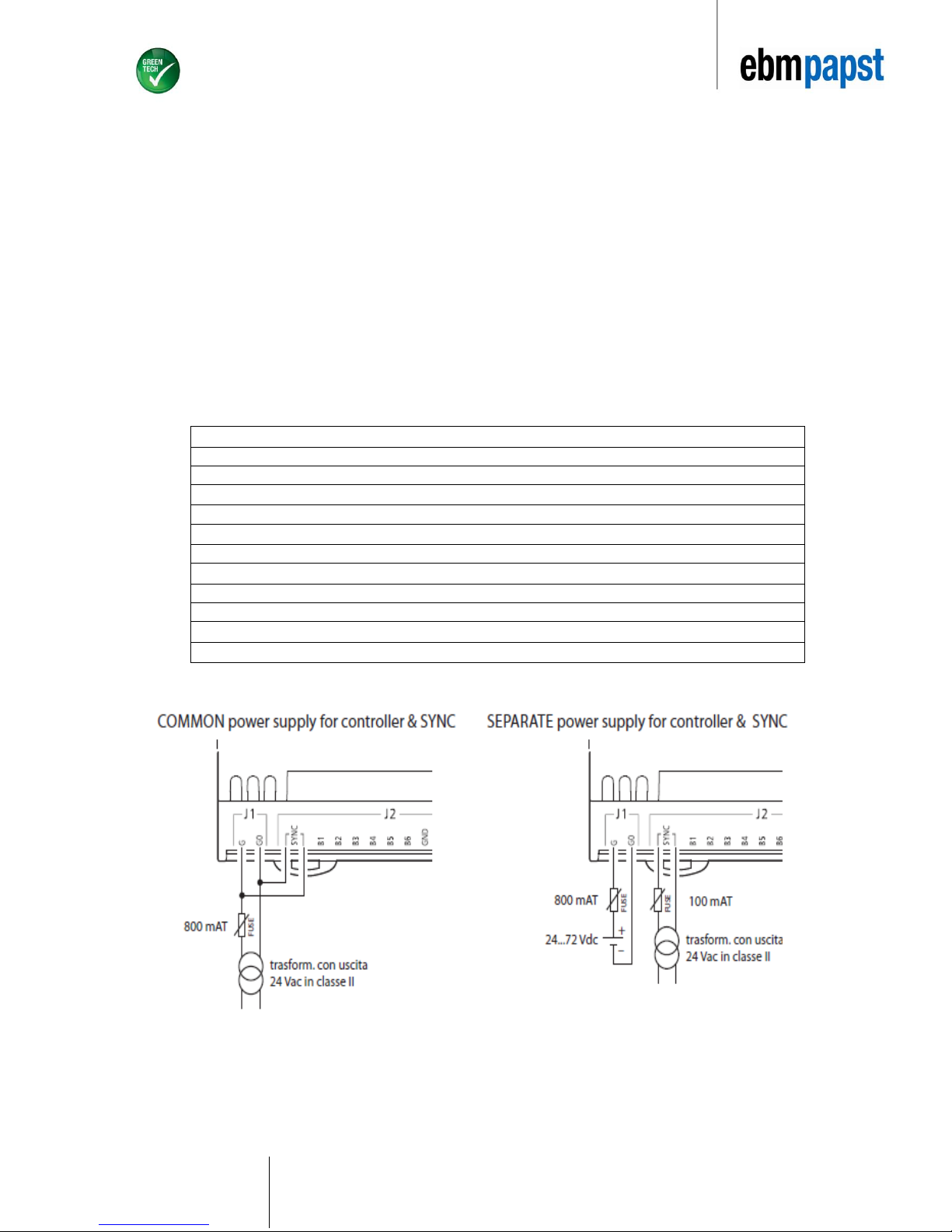
2.2 Power Supply
2.2.1 AC
The power supply is connected between G and G0 (Cf. Figure 1a). For AC installation, it is recommended to use a 30 VA class
2 safety transformer that provides an output voltage of 24 Vac. This is to supply a single EC-FAN GATEWAY only. When
supplying multiple EC-FAN GATEWAY controllers with the same transformer, the transformer’s rated power must be n x 30VA,
where “n” represents the number of EC-FAN GATEWAY controllers being supplied by this transformer.
2.2.2 DC
The power supply is connected between G and G0 (Cf. Figure 1b). The voltage supply required is 48 VDC (36V min to 72V
max).
2.2.3 Fuse
The power supply to the EC-FAN GATEWAY and terminal (or series of EC-FAN GATEWAYs and terminals) should be
separate from the power supply to the other electrical devices (contactors and other electromechanical components) inside the
electrical panel. A 250 V 800 mAT fuse must be installed in the power supply line. The power supply is functionally insulated
from the rest of the I/O circuit, including the serial connections.
2.3 Installation warnings
2.3.1 Operating Environment
Avoid assembling the EC-FAN GATEWAY controller in environments with the following characteristics:
• Relative humidity greater than 90%
• Strong vibrations or knocks
• Exposure to continuous water sprays
• Exposure to corrosive or pollutant gases (e.g. sulphur or ammonia fumes, saline mist, smoke). This is to avoid
corrosion
• and oxidation of the controller unit
• Strong magnetic and/or radio interference. Avoid installation of the EC-FAN GATEWAY close to transmitting
antennas
• Large and rapid ambient temperature fluctuations
• Environments where explosive mixes of flammable gases are present
• Exposure to dust
2.3.2 Connecting the EC-FAN GATEWAY
• Using an inappropriate power supply from the one specified could seriously damage the EC-FAN G ATEWAY.
• Use cable ends that are suitable for the terminals. Loosen each screw and insert the cable ends, then tighten the
screws once completed, lightly tug at the cables to ensure that they are appropriately fitted.
• Avoid touching or coming into close contact with the electronic components fittet on the boards. This is
recommended to avoid electrostatic discharges from the operator to the components. Electrostatic discharges can
have an extremely detrimental effect on the functionality of the EC-FAN GATEWAY.
• Disconnect the controller from the power supply before performing any maintenance or assembly
connections/operations.
• If and when the EC-FAN GATEWAY is not used in the manner specified by the manufacturer, the rated protection of
the device may be compromised.
Page 5
Pa
Page 3 of 15
ebm-papst A&NZ Pty Ltd 10 Oxford Road · Laverton North VIC 3026 · Phone +61 (03) 9360 6400 · Fax +61 (03) 9360 6464
ABN 33 115 927 556 NSW Phone +61 (02) 9827 6400 · NSW Fax +61 (02) 9827 6464 · NZ Phone +64 (09) 525 0245 · NZ Fax +64 (09) 525 0246
sales@ebmpapst.com.au · www.ebmpapst.com.au
3 TECHNICAL SPECIFICATIONS
3.1 Scope of delivery
• Supernode
• Removable screw connector kit for Supernode
• BACnet, Ethernet serial card
3.2 Mechanical specifictions
• Assembly DIN rail
3.3 Plastic Case
• Fitted on DIN rail as per DIN 43880 and IEC EN 50022
• Material: technopolymer
• Flame retardance: V0 (UL94) and 960 °C (IEC 695)
• Ball pressure test 125 °C
• Resistance to creeping current ≥ 250 V
3.4 Electrical specifications
Isolated power supply DC power supply: 48 VDC (36 V minimum to 72 V maximum)
AC power supply: 24 VAC +10% to -15 %, 50/60 Hz
Maximum power input: P= 6 W, S= 8 VA
CPU H8SX/1651 32-bit, 50 MHz
FLASH program memory 2+2 Mbytes
SRAM data memory 512 kBytes, 16-bit
Parameter data memory 13 kBytes + additional 32 kB EEPROM
NAND FLASH memory 32 Mbytes
Duration of working cycle 0.2 s typical (applications of average complexity)
Clock Available as standard and integrated on main board with CR2430 3 VDC lithium battery
Terminal block male/female plug-in connectors, max voltage 250 VAC;
Cable size: min 0.5 mm ² – max 2.5 mm ²
3.5 Electrical connection
Figure 1a Figure 1b
Page 6

Pa
Page 4 of 15
ebm-papst A&NZ Pty Ltd 10 Oxford Road · Laverton North VIC 3026 · Phone +61 (03) 9360 6400 · Fax +61 (03) 9360 6464
ABN 33 115 927 556 NSW Phone +61 (02) 9827 6400 · NSW Fax +61 (02) 9827 6464 · NZ Phone +64 (09) 525 0245 · NZ Fax +64 (09) 525 0246
sales@ebmpapst.com.au · www.ebmpapst.com.au
4 MECHANICAL DIMENSIONS
5 CONNECTORS
1. Power supply connector ( G=, G0-) 24 VAC or 48 VDC
2. Opto isolated “Field Bus” serial connector
Figure 2
Figure 3
Page 7

Pa
Page 5 of 15
ebm-papst A&NZ Pty Ltd 10 Oxford Road · Laverton North VIC 3026 · Phone +61 (03) 9360 6400 · Fax +61 (03) 9360 6464
ABN 33 115 927 556 NSW Phone +61 (02) 9827 6400 · NSW Fax +61 (02) 9827 6464 · NZ Phone +64 (09) 525 0245 · NZ Fax +64 (09) 525 0246
sales@ebmpapst.com.au · www.ebmpapst.com.au
6 INSTALLATION
6.1 User Interface and LED Buttons
pCOWeb (Figure 4) features a button (PUSHBUTTON) and
two indicator LEDs (STATUS LED and ETHERNET LED)
Functions of the button
When starting up the pCOWeb, the push button is used to select the network communication type - either factory parameters
or user parameters. In the case of the EC-FAN GATEWAY the parameters have already been pre-programmed for the
customer. There is no requirement for the customer to select network communication.
6.2 Push button & LEDs
When the Ethernet LED is in a solid green state, this indicates successful connectivity between the PC and the EC-FAN
GATEWAY. When the status LED is green, this indicateds successul communication between PC (pCOWeb software) and
the EC-FAN GATEWAY.
Immediately after reboot, as soon as the Status LED remains on steady GREEN, hold the button; after around 20 seconds
the Status LED will turn RED and flash slowly 3 times. The button must be released before the end of the 3 flashes. This
process has to be done only once at the point of programming the device.
In normal operation, the push button reboots pCOWeb without needing to disconnect the power supply. The customer is
not recommended to reboot the system via the push button as this is done by the pCOWeb webpage that is to be
set up in Section 7.5.
6.3 Connection
Connect pCOWeb to the Ethernet connector on the PC using a crossover cable (Figure 4). Please note that the crossover
cable is not part of the scope of delivery.
6.4 Adressing fans
• Before the set up of the EC-FAN GATEWAY the number of active ebm-papst fans that are to be connected to the
ECFAN GATEWAY will have to be pre-programmed via EC-Control. EC-Control is to be used to assign addresses for the
respective fans.
• The EC-FAN GATEWAY will not automatically assign addresses to the fans that are required on its network.
• ebm-papst recommends that the first fan be programmed at address 2 and the following fans thereafter to be programmed
at “n+1”.This is to avoid any confusion when a new fan unit is to be added to an existing network. Ebmpapst fans are by factory
default addressed 1.
• Ensure that the fans are not connected to the EC-FAN GATEWAY before the device has been appropriately
programmed. Power down the fans. Attach the communication cables to point 2 as per Figure 3 and power up the fans.
Figure 4 LED Indicators
Figure 5 pCOWeb to PC connection
Page 8

Pa
Page 6 of 15
ebm-papst A&NZ Pty Ltd 10 Oxford Road · Laverton North VIC 3026 · Phone +61 (03) 9360 6400 · Fax +61 (03) 9360 6464
ABN 33 115 927 556 NSW Phone +61 (02) 9827 6400 · NSW Fax +61 (02) 9827 6464 · NZ Phone +64 (09) 525 0245 · NZ Fax +64 (09) 525 0246
sales@ebmpapst.com.au · www.ebmpapst.com.au
6.5 Installing fans to be recognized by the EC-FAN GATEWAY
Once the EC-FAN GATEWAY device has locaded the following screen will appear:
6.5.1 Assigning the number of active devices
Select “d. Service Settings” by using arrows.
Press
6.5.2 Password Entry
The default password is “1234”.
Use arrows to scroll in order to obtain desired values for
Password entry.
Once desired values are obtained, press
Press once to access Main Menu
(At any point during the setup, pressing will return to user to
the main menu.)
Use arrows to locate “Service” command.
Press
Figure 7
Figure 8
Figure 6
Page 9

Pa
Page 7 of 15
ebm-papst A&NZ Pty Ltd 10 Oxford Road · Laverton North VIC 3026 · Phone +61 (03) 9360 6400 · Fax +61 (03) 9360 6464
ABN 33 115 927 556 NSW Phone +61 (02) 9827 6400 · NSW Fax +61 (02) 9827 6464 · NZ Phone +64 (09) 525 0245 · NZ Fax +64 (09) 525 0246
sales@ebmpapst.com.au · www.ebmpapst.com.au
6.5.3 Choosing the number of devices
Choose “a.Settings” by using to scroll and press to choose
option.
Press to edit the number of devices in use.
Select total number of devices that are to be connected by scrolling
. Press once desired value is obtained (as shown in Figure
9).
The Univeral Gateway device recognises a maximum of 30 fans.
Offline Delay and Offline Recall are set a default of 10s and 2s
respectively.
User to choose mode of fan control by scrolling .
Press once desired option is selected.
On the same screen scroll down and push for Enable Fan
option. Select “YES” for Enable Fan option by using and
press . Select “YES” for all fans that are to be active. All active
fans can be controlled by the administrator. If this option is selected
as “NO”, you will not be able to configure the respective fan nor will
the fan show as an active device.
Exit screen by pressing .
Choose value 12 for both “Ramp up time” and “Ramp down time” using
. Once desired value is selected press .
“Run Direction” will have to be checked against the respective fan
Datasheet. If in doubt, consult your ebm-papst representative.
Run direction: right = clockwise; left = counterclockwise.
Figure 9
Figure 10
Figure 11
Page 10

Pa
Page 8 of 15
ebm-papst A&NZ Pty Ltd 10 Oxford Road · Laverton North VIC 3026 · Phone +61 (03) 9360 6400 · Fax +61 (03) 9360 6464
ABN 33 115 927 556 NSW Phone +61 (02) 9827 6400 · NSW Fax +61 (02) 9827 6464 · NZ Phone +64 (09) 525 0245 · NZ Fax +64 (09) 525 0246
sales@ebmpapst.com.au · www.ebmpapst.com.au
6.5.4 Adressing the fans on the EC-FAN GATEWAY controller
Press 3 times to return to Main Menu.
Select “C. Manufacturer”, enter default password as described in
Selection 6.5.2 and then select “b.I/O Configuration“ by scrolling
via and pressing .
Here you will assign the appropriate address to the respective Fan.
The address entered will have match the address that has been
initially assigned to the fan via EC-Control. Repeat steps for multiple
fans.
ebm-papst recommends that the first fan be programmed at
address 2 and the following fans thereafter to be programmed at
„n+1“.
6.5.5 Manually setting speed
Choose the following option if you want to manually control the fan
speed:
Select “B”. Service, press .
Select “d.Service Settings”, press .
Select “b.Manual”.
Figure 12
Figure 13
Figure 14
Page 11

Pa
Page 9 of 15
ebm-papst A&NZ Pty Ltd 10 Oxford Road · Laverton North VIC 3026 · Phone +61 (03) 9360 6400 · Fax +61 (03) 9360 6464
ABN 33 115 927 556 NSW Phone +61 (02) 9827 6400 · NSW Fax +61 (02) 9827 6464 · NZ Phone +64 (09) 525 0245 · NZ Fax +64 (09) 525 0246
sales@ebmpapst.com.au · www.ebmpapst.com.au
Press to access edit mode. Here you can enter
the desired speed as described in the below steps.
Speed is displayed in rpm. Press or to aquire
desired speed value.
Press again once appropriate speed is selected. Fan
will operate at requested speed.
Repeat speed if there is more than one fan in the
application. Note: following recovery from a power failure
the device will revert to the rpm value that is entered in
“manual value”.
6.5.6 Viewing real-time fan data
Return to the main menu by pushing or .
Pressing or keys will allow the user to view data for the
specific fan that is desired.
6.5.7 Alarm
In case the fans have been disconnected from the device or if they are not addressed appropriately the EC-FAN GATEWAY
will give off an audible alarm.
To view the alarm, press . The description of the respective problem will be displayed in the alarm log.
Once you have viewed the alarm screen, press . The beeping sound will cease.
Unless the problem is rectified, the EC-FAN GATEWAY will continue to indicate an alarm warning. The beeping sound will persist and the
description of the respective problem will be displayed in the alarm log.
Figure 15
Figure 16
Page 12

Pa
Page 10 of 15
ebm-papst A&NZ Pty Ltd 10 Oxford Road · Laverton North VIC 3026 · Phone +61 (03) 9360 6400 · Fax +61 (03) 9360 6464
ABN 33 115 927 556 NSW Phone +61 (02) 9827 6400 · NSW Fax +61 (02) 9827 6464 · NZ Phone +64 (09) 525 0245 · NZ Fax +64 (09) 525 0246
sales@ebmpapst.com.au · www.ebmpapst.com.au
7 WEB BROWSER SET UP
7.1 LAN Connection
The EC-FAN GATEWAY offers the option of a web browser where the BACnet settings for the device will be accessible via
this browser. Speed settings can also be manually set via the browser. By default the EC-FAN GATEWAY has been set to IP
address of 172 .16.0.1, subnet mask 255.255.0.0.
Follow these steps to set up the web browser:
Turn “OFF” all wireless and Bluetooth networks on the computer/laptop
•Start à Control Panel à View Network Status à Connections à Properties à Internet Protocol Version
4 ( TCP/ IPv4)
After double clicking Internet Protocol Version 4 (TCP/IPv4), choose “Use the following IP address”
Enter IP address 172.16.0.10 and Subnet Mask 255.255.0.0 in the appropriate fields as shown in Figure 17.
Figure 17 Internet Protocol Version 4 (ECP/IPv4)
Follow through with the above steps and click “OK” to establish
a local area connection between your laptop and the EC FAN
GATEWAY.
Open a web browser (Internet Explorer version 7 or greater,
Google Chrome or Mozilla Firefox).
7.2 Entering desired rpm values
Type 172.16.0.1 into the address bar of the web browser. The below page will be accessed (Figure 18). The active fans will
be highlighted in green.
Figure 18 ebm-papst web front
Click on Fan 1 icon to open browser for speed settings.
Here you are provided with an extra option where you can enter the
desired rpm value. Note that all desired rpm values entered here
will have to be multiplied by 0.1. Therefore, if an rpm of 500 is
desired, the value to be entered is 50.
7.3 Accessing pCOWeb from a PC
To access the BACnet settings of the device, scroll down on the ebm-papst web front browser and locate “Admin Page”. Click
on “Admin Page”. You will be prompted to enter a username and password.
Username: admin, Password: fadmin
You will now have access to pCOWeb.
Page 13

Pa
Page 11 of 15
ebm-papst A&NZ Pty Ltd 10 Oxford Road · Laverton North VIC 3026 · Phone +61 (03) 9360 6400 · Fax +61 (03) 9360 6464
ABN 33 115 927 556 NSW Phone +61 (02) 9827 6400 · NSW Fax +61 (02) 9827 6464 · NZ Phone +64 (09) 525 0245 · NZ Fax +64 (09) 525 0246
sales@ebmpapst.com.au · www.ebmpapst.com.au
7.4 Configuration Settings
Figure 19 BACnet Settings
Click on the “Configuration” tab followed by BACnet
Choose BACnet Ethernet as your LAN type
The variable in the pCOWeb Device Instance shown
in Figure 19 is what the EC-FAN GATEWAY will be
described as in BACnet BMS network. By default this
description is 77000.
This can be changed accordingly if desired.
7.5 Changing IP addresses
Figure 20 IP Address Settings
Click Network tab. By default the product has an IP
address of 172.16.0.1. Here the user can allocate
their desired IP address.
Please note that if the IP address is changed here,
the next time the ebm-papst web front browser is to
be accessed, steps in Section 7.1 will have to be
repeated.
When an IP address is changed the EC-FAN
GATEWAY is required to undergo a “Reboot”. This
can be achieved by clicking on “Reboot” as shown in
Figure 20.
Enter appropriate IP address under IP address main
and an appropriate subnet mask under NetMask
main.
7.6 MODBUS
Figure 21 MODBUS Protocol
Select pCO Com tab followed by MODBUS
Extended as the protocol for all ebm-papst fans.
Also ensure that the settings are as per Figure
21.
When MODBUS Extended is selected as the
protocol, this allows the gateway to be able to
communicate with ebmpapst fans on the same
protocol platform.
Ensure that MODBUS Extended is selected
for ebm-papst fans.
Page 14

Pa
Page 12 of 15
ebm-papst A&NZ Pty Ltd 10 Oxford Road · Laverton North VIC 3026 · Phone +61 (03) 9360 6400 · Fax +61 (03) 9360 6464
ABN 33 115 927 556 NSW Phone +61 (02) 9827 6400 · NSW Fax +61 (02) 9827 6464 · NZ Phone +64 (09) 525 0245 · NZ Fax +64 (09) 525 0246
sales@ebmpapst.com.au · www.ebmpapst.com.au
7.7 READ / WRITE VARIABLES
Figure 20 describes the “Read and Write” type variables for the first MODBUS fan (Fan 1) in an installation. Take note that
each MODBUS fan has 30 registers assigned on the EC-Fan Gateway device.
Please apply the formula found under Register Number Fan (X) to determine the appropriate register number for the
different variables that represent Fan2,3 … 31. For example, if you were to change the “Ramp Up” time on Fan 2 then you
will be writing a value at register 43 (30(2-1)+13 = 43). Subsequently, the “Ramp Up” time for Fan 3 is assigned to register
73.
Take note that if the address is changed digitally via the building management system, this address change will also have
to be implemented on the EC-Fan Gateway device.
Once the above steps are completed your EC-FAN GATEWAY has been successfully set up.
If you have further questions please contact your ebm-papst representative or your nearest ebm-papst office.
Register Number Fan 1 Register Number Fan (X) Register Type Comments
Fan Address 1
Write Values
Speed Input 5
Write Values
Ramp Up 13
Write Values
Ramp Down 14
Write Values
(30(x-1)+ Register
Number Fan 1)
Take note all
variables are at a
Factor of 0.1
Maximum Speed 12
Read Only
Actual Speed 19
Read Only
DC Link Voltage 21
Read Only
DC Link Current 22
Read Only
Input Power 23
Table 1 Read and Write variale registers
Page 15

Pa
Page 13 of 15
ebm-papst A&NZ Pty Ltd 10 Oxford Road · Laverton North VIC 3026 · Phone +61 (03) 9360 6400 · Fax +61 (03) 9360 6464
ABN 33 115 927 556 NSW Phone +61 (02) 9827 6400 · NSW Fax +61 (02) 9827 6464 · NZ Phone +64 (09) 525 0245 · NZ Fax +64 (09) 525 0246
sales@ebmpapst.com.au · www.ebmpapst.com.au
2017/09 v9
 Loading...