

Page 1
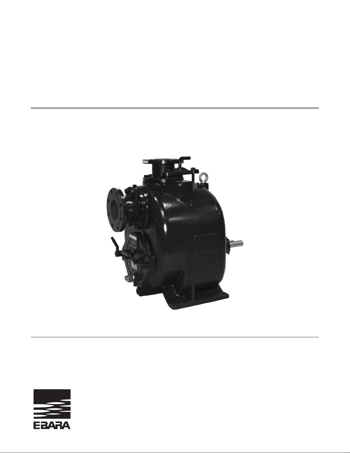
Self Priming Trash Pump
Model EFQT-12
+/0 )) 0',+-$. 0',+ +# '+0$+ +"$ +1 )
+0$.+ 0',+ ),.-,. 0',+
Page 2

TABLE OF CONTENTS
INTRODUCTION........................................................................................... Pg. 03
WARNING – SECTION A ............................................................................ Pg. 04
INSTALLATION – SECTION B.................................................................... Pg. 05
Pump Dimensions...................................................................... Pg. 05
PREINSTALLATION INSPECTION................................................. Pg. 06
POSITIONING PUMP...................................................................... Pg. 06
Lifting.......................................................................................... Pg. 06
Mounting..................................................................................... Pg. 06
Clearance................................................................................... Pg. 06
SUCTION AND DISCHARGE PIPING............................................. Pg. 06
Materials..................................................................................... Pg. 06
Line Configuration...................................................................... Pg. 07
Connections to Pump................................................................. Pg. 07
Gauges....................................................................................... Pg. 07
SUCTION LINES.............................................................................. Pg. 07
Fittings........................................................................................ Pg. 07
Strainers..................................................................................... Pg. 07
Sealing....................................................................................... Pg. 07
Suction Lines in Sumps.............................................................. Pg. 07
Suction Lines Positioning........................................................... Pg. 08
DISCHARGE LINES......................................................................... Pg. 08
Siphoning................................................................................... Pg. 08
Valves......................................................................................... Pg. 08
Bypass Lines.............................................................................. Pg. 09
AUTOMATIC AIR RELEASE VALVE............................................... Pg. 10
Theory of Operation................................................................... Pg. 10
Air Release Valve Installation..................................................... Pg. 10
ALIGNMENT.................................................................................... Pg. 11
Coupled Drivers.......................................................................... Pg. 12
V-Belt Drives.............................................................................. Pg. 12
OPERATION – SECTION C.........................................................................
Pg. 14
PRIMING.......................................................................................... Pg. 14
STARTING....................................................................................... Pg. 14
Rotation...................................................................................... Pg. 14
OPERATION.................................................................................... Pg. 15
Lines With a Bypass................................................................... Pg. 15
Lines Without a Bypass.............................................................. Pg. 15
Leakage...................................................................................... Pg. 15
Liquids Temperature and Overheating....................................... Pg. 15
Strainer Check............................................................................ Pg. 16
Pump Vacuum Check................................................................. Pg. 16
STOPPING....................................................................................... Pg. 16
Cold Weather Preservation........................................................ Pg. 16
BEARING TEMPERATURE CHECK............................................... Pg. 16
EBARA Fluid Handling 1
Page 3

PERFORMANCE CURVE……………………………………….......... Pg. 21
Pump Model and Repair Rotating Assembly ....………….......... Pg. 22
PARTS LISTS ................................................................................. Pg. 23
PUMP AND SEAL DISASSEMBLY AND REASSEMBLY…............ Pg. 25
Suction Check Valve Disassembly ………………………........... Pg. 25
Pump Disassembly …………………………………………......... Pg. 25
Seal Disassembly …………………………..………………......... Pg. 26
Impeller Shaft and Bearing Disassembly .......……………......... Pg. 27
Impeller Shaft and Bearing Reassembly ……….........….......... Pg. 27
Seal Reassembly …………..……….……………………............ Pg. 28
Pump Reassembly …………………………………………......... Pg. 29
Suction Check Valve Reassembly ………………………............ Pg. 30
Seal Assembly ......................................................................... Pg. 30
Bearings .................................................................................... Pg. 30
TROUBLESHOOTING – SECTION D ………………………............ Pg. 18
PUMP MAINTENANCE AND REPAIR – SECTION E……….......... Pg. 21
LUBRIFICATION ............................................................................ Pg. 30
TABLE OF CONTENTS
(Continued)
EBARA Fluid Handling 2
Page 4
INTRODUCTION
p
This Installation, Operation, and
Maintenance manual is designed to help
you get the best performance and
longest life from your EBARA pump.
This pump is a EFQT Series, semi-open
impeller, self- priming centrifugal model
with a suction check valve.
If there are any questions regarding the pump or its applications which are not covered in this manual or
in other literature accompanying this unit, please contact your EBARA distributor, or write:
The pump is designed for handling mild
industrial corrosives, mud or slurries
containing large entrained solids. The basic
material of construction is gray iron, with
ductile iron impeller and steel wearing parts.
EBARA Fluid Handling
1651 Cedar Line Drive
Rock Hill, SC 29730
For information or technical assistance on the power source, contact the power source manufacture’s
local dealer or representative.
The following are used to alert maintenance personnel to procedures which require special attention, to
those which could damage equipment, and to those which could be dangerous to personnel:
Immediate hazards which WILL result in
severe personal injury or death. These
instructions describe the procedure required
and the injury which will result from failure
to follow procedure.
DANGER!
Hazardous or unsafe practices could result in
minor personal injury, product or property
damage. These instructions describe the
requirements and the possible damage which
could result from failure to follow the
rocedure.
Instructions to aid in installation, operation,
and maintenance or which clarify a procedure.
CAUTION!
NOTE
EBARA Fluid Handling 3
Page 5
SAFETY – SECTION A
These warnings apply to EFQT series basic
pumps. EBARA has no control over or particular
knowledge of the power source which will be
used. Refer to the manual accompanying the
power source before attempting to begin
operation.
WARNING!
Before attempting to open or service the
pump
1. Familiarize yourself with this manual.
2. Disconnect or lock out the power source to
ensure that the pump will remain inoperative.
3. Allow the pump to cool if overheated.
4. Check the temperature before opening any
covers, plates, or plugs.
5. Close the suction and discharge valves.
6. Vent the pump slowly and cautiously.
7. Drain the pump
This pump is designed to handle mild
industrial corrosives, mud or slurries
containing large entrained solids. Do not
attempt to pump volatile, corrosive, or
flammable materials which may damage the
pump or endanger personnel as result of
pump failure.
:
WARNING!
WARNING!
After the pump has been positioned, make
certain that the pump and all piping
connections are tight, properly supported and
secure before operation.
WARNING!
Do not operate the pump without the guards in
place over the rotating parts.
Exposed rotating parts can catch clothing,
fingers, or tools, causing severe injury to
personnel.
WARNING!
Do not remove plates, covers, gauges, pipe
plugs, or fittings from an overheated pump.
Vapor pressure within the pump can cause parts
being disengaged to be ejected with great force.
Allow the pump to cool before servicing.
WARNING!
Do not operate the pump against a closed
discharge valve for long periods of time. If
operated against a closed discharge valve, pump
components will deteriorate, and the liquid could
come to a boil, pressure, and cause the pump
casing to rupture or explode .
WARNING!
Use lifting and moving equipment in good repair
and with adequate capacity to prevent injuries to
personnel or damage to equipment. Suction and
discharge hoses and piping must be removed
form the before lifting
EBARA Fluid Handling 4
Page 6
INSTALLATION – SECTION B
Review all SAFETY information in Section A.
Since pump installations are seldom identical, this
section offers only general recommendations and
practices required to inspect, position and arrange
the pump and piping.
Most of the information pertains to a standard
static lift application where the pump is
positioned above the level of liquid to be pumped.
If installed in a flooded suction application
where the liquid is supplied to the pump under
pressure, some of the information such as
mounting, line configuration, and priming must be
tailored to the specific application.
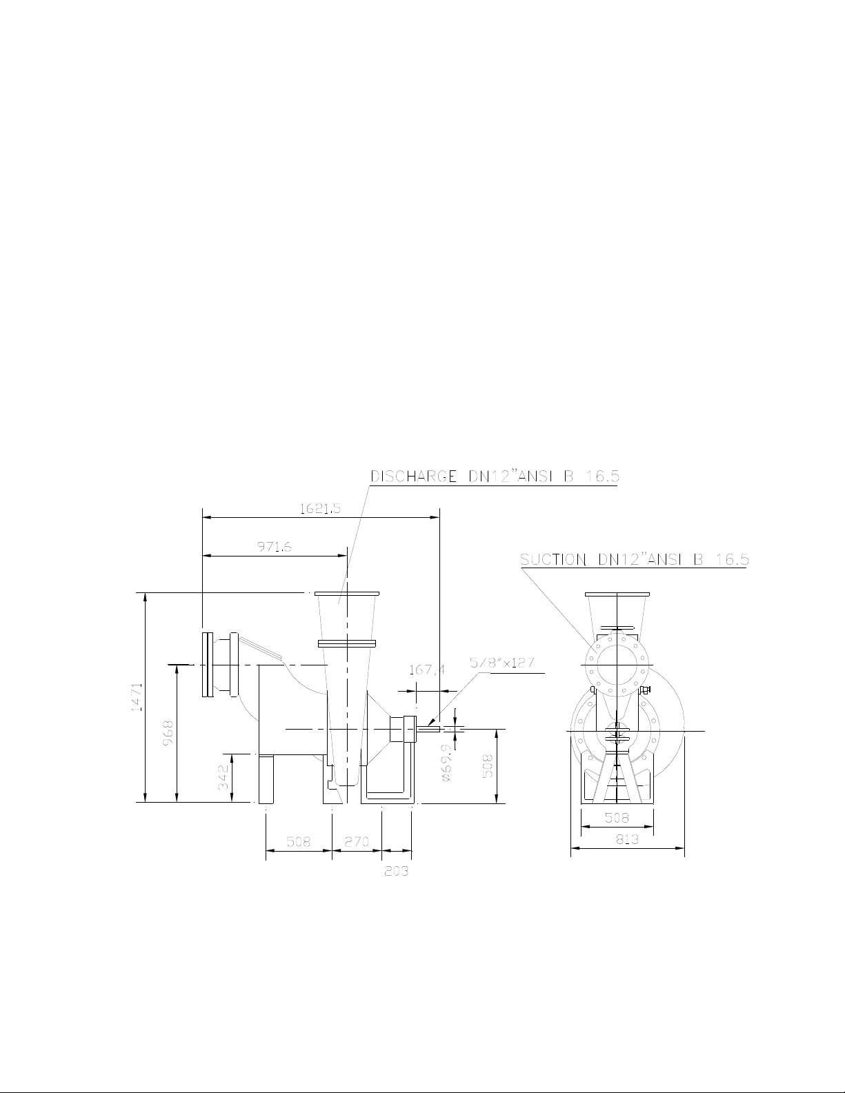
OUTLINE DRAWING
Figure 1 Pump Model EFQT-12
Since the pressure supplied to the pump is critical to
performance and safety, be sure to limit incoming
pressure to 50% of the maximum permissible
operating pressure as shown on the pump
performance curve.
For further assistance, contact your EBARA
distributor or EBARA Fluid Handling.
Pump Dimensions
See Figure 1 for the approximate physical
dimensions of this pump.
EBARA Fluid Handling 5
Page 7
PREINSTALLATION INSPECTION POSITIONING PUMP
The pump assembly was inspected and tested
before shipment from the factory. Before
installation, inspect the pump for damage which
may have occurred during shipment. Check as
follows:
Only operate this pump in the direction
indicate by the arrow on the pump body and
on the accompanying decal. Refer to
ROTATION
If the maximum shelf life has been exceeded,
or if anything appears to be abnormal, contact
your EBARA distributor or the factory to
determine the repair or updating policy. Do not
put the pump into service until appropriate
action has been taken.
a. Inspect the pump for cracks, dents,
damaged threads, and other obvious
damage.
b. Check for and tighten loose attaching
fasteners. Since gaskets tend to shrink
after drying, check for loose hardware at
mating surfaces.
c. Carefully read all warnings and cautions
contained in this manual or affixed to the
pump, and perform all duties indicated.
Note the direction of rotation indicated on
the pump. Check that the pump shaft
rotates counterclockwise when facing the
back cover plate assembly/impeller end of
the pump.
CAUTION!
in OPERATION, Section C.
d. Check levels and lubricate as
necessary. Refer to LUBRICATION
MAINTENANCE AND REPAIR
this manual and perform duties as
instructed.
e. If the pump and power source have
been stored for more than 12 months,
some of the components or lubricants may
have exceeded their maximum shelf life.
These must be inspected or replaced
ensure maximum pump service.
EBARA Fluid Handling 6
in the
section of
to
Lifting
Use lifting equipment with a capacity of at least
13.230 pounds (6000 Kg). This pump weighs
approximately 2350 pounds (1066 Kg), not
including the weight of accessories and base.
Customer installed equipment such as suction and
discharge piping must be removed before
attempting to lift.
The pump assembly can be seriously
damaged if the cables or chains used to lift
and move the unit is improperly wrapped
around the pump.
Mounting
Locate the pump in an accessible place as close as
practical to the liquid being pumped. Level mounting
is essential for proper operation.
The pump may have to be supported or shimmed to
provide for level operation or to eliminate vibration.
Clearance
When positioning the pump, allow a minimum
clearance of 40 inches (800 mm) in front of the back
cover to permit removal of the cover and easy
access to the pump interior.
SUCTION AND DISCHARGE PIPING
Pump performance is adversely affected by
increase suction lift, discharge elevation and friction
losses. See the performance curve and operating
range shown on Page 21 to be sure your overall
application allows pump to operate within the
safe operation range.
Materials
Either pipe or hose maybe used for suction and
discharge lines: however, the materials must be
compatible with liquid being pumped.
CAUTION!
Page 8

If hose is used in suction lines, it must be the
rigid-wall, reinforced type to prevent collapse
under suction. Using piping couplings in suction
lines is not recommended.
Line Configuration
Keep suction and discharge lines as straight as
possible to minimize friction losses. Make
minimum use of elbows and fittings, which
substantially increase friction loss. If elbows are
necessary, use the long radius type to minimize
friction loss.
Connections to Pump
Before tightening a connecting flange, align it
exactly with the pump port. Never pull a pipe line
into place by tightening the flange bolts and/or
couplings.
Lines near the pump must be independently
supported to avoid strain on the pump which
could cause excessive vibration, decrease
bearing life, and increased shaft and seal wear.
If hose-type lines are used, they should have
adequate support to secure them when filled
with liquid and under pressure.
Gauges
Most pumps are drilled and tapped for installing
discharge pressure and vacuum suction gauges.
If these gauges are desired for pumps that are
not tapped, drill and tap the suction and
discharge lines not less than 18 inches
(457,2mm) from the suction and discharge ports
and install the lines. Installation closer to the
pump may result in erratic readings.
SUCTION LINES
To avoid air pockets which could affect pump
priming, the suction line must be as short and
direct as possible. When operation involves a
suction lift, the line must always slope upward to
the pump from the source of the liquid being
pumped: if the line slopes down to the pump at
any point along the suction run, air pockets will
be created.
Fittings
Suction lines should be the same size as the pump
inlet. If reducers are used in suction lines, they should
be the eccentric type, and should be installed with the
flat part of the reducers uppermost to avoid creating
air pockets. Valves are not normally used in suction
lines, but if a valve is used, install it with the horizontal
to avoid air pockets.
Strainers
If a strainer is furnished with the pump, be certain to
use it; any spherical solids which pass through a
strainer furnished with the pump will also pass
through the pump itself.
If a strainer is not furnished with the pump, but is
installed by the pump user, make certain that the total
area of the openings in the strainer is at least three or
four times the cross section of the suction line, and
that the openings will not permit passage of solids
larger than the solids handling capability of the pump.
This pump is designed to handle up to 3 inch (76,2
mm) diameter spherical solids.
Sealing
Since even a slight leak will affect priming, head, and
capacity, especially when operating with a high
suction lift, all connections in the suction line should
be sealed with pipe dope to ensure an airtight seal.
Follow the sealant manufacturer’s recommendations
when selecting and applying the pipe dope. The pipe
dope should be compatible with the liquid being
pumped.
Suction Lines in Sumps
If a single suction line is installed in a sump, it should
be positioned away from the wall of the sump at a
distance equal to 1 ½ times the diameter of the
suction line.
If there is a liquid flow from an open pipe into the
sump, the flow should be kept away from the suction
inlet because the inflow will carry air down into the
sump, and air entering the suction line will reduce
pump efficiency.
EBARA Fluid Handling 7
Page 9
If it is necessary to position inflow close to
the suction inlet, install a baffle between the
inflow and the in suction lines, it must be the
rigid-wall, reinforced type to prevent collapse
under suction. Using piping couplings in
suction lines is not recommended. Suction
inlet at a distance 1 ½ times the diameter of
the suction pipe. The baffle will allow
entrained air to escape from the liquid before
it is drawn into the suction inlet.
If two suction lines are installed a single
sump, the flow paths may interact, reducing
the efficiency of one or both pumps. To avoid
this, position the suction inlets so that they
are separated by a distance equal to at least
3 times the diameter of the suction pipe.
Suction Line Positioning
The depth of submergence of the suction line is
critical to efficient pump operation. Figure 2 shows
Recommended minimum submergence vs. velocity.
NOTE
The pipe submergence required may be reduced
by installing a standard pipe increaser fitting at
the end of the suction line. The larger opening
size will reduce the inlet velocity. Calculate the
required submergence using the following
formula based on the increased opening size
(area or diameter).
VELOCITY (FT./SEC.)= QUANT. (G.P.M)x.321
AREA D²
VELOCITY (M./SEC.)= FLOW (M./MIN)x21.22
DIAMETER IN MM² AREA IN M²
Figure 2. Recommended Minimum Suction Line Submergence vs. Velocity
DISCHARGE LINES
Siphoning
Do not terminate the discharge line at a level lower
than of the liquid being pumped unless a siphon
breaker is used in the line. Otherwise, a siphoning
action causing damage to the pump could result.
EBARA Fluid Handling 8
OR G.P.M. x 4085
OR FLOW (M³/SEC.)
Valves
If a throttling valve is desired in the discharge line,
use a valve as large as the largest pipe to minimize
friction losses. Never install a throttling valve in a
suction line.
With high discharge heads, it is recommended that a
throttling valve and a system check valve be installed
in the discharge line to protect the pump from
excessive shock pressure and reverse rotation when
it is stopped.
Page 10
If the application involves a high discharge head,
gradually close the discharge throttling valve before
stopping the pump.
Bypass Lines
Self-priming pumps are not air compressors. During
the priming cycle, air from the suction line must be
vented to atmosphere on the discharge side. If the
discharge line is open and a check valve has been
installed in the discharge line, the discharge side of
the pump must be opened to atmospheric pressure
through a bypass line installed between the pump
discharge and the check valve. A self-priming
centrifugal pump will not prime if there is sufficient
static liquid head to hold the discharge check valve
closed.
NOTE
The bypass line should be sized so that it does
not affect pump discharge capacity; however,
the bypass line should be at least 1 inch in
diameter to minimize the chance of plugging.
In low discharge head applications (less than 30
feet or 9 meters), it is recommended that the bypass
line be run back to the wet well, and locate 6 inches
below the water level or cut-off point of the level
pump. In some installations, this bypass line may be
terminated with a six-to-eight foot length of 1 ¼ inch
ID. smooth-bore hose; air and liquid vented during
the priming process will then agitate the hose and
break up any solids, grease, or other substances
likely to cause clogging.
CAUTION!
CAUTION!
A bypass line that is returned to a wet well must
be secured against being drawn into the pump
suction inlet.
It is also recommended that pipe unions be installed
at each 90º elbow in a bypass line to ease
disassembly and maintenance.
EBARA Fluid Handling 9
In high discharge head applications (more than
30 feet), an excessive amount of liquid may be
bypassed and forced back to the wet well under
the full working pressure of the pump; this will
reduce overall pumping efficiency. Therefore, it is
recommended that a EBARA Automatic Air
Release Valve be installed in the bypass line.
EBARA Automatic Air Release Valves are reliable,
and require minimum maintenance. See
AUTOMATIC AIR RELEASE VALVE in this
section for installation and theory of operation of
the Automatic Air Release Valve. Contact EBARA
Fluid Handling for selection of an Automatic Air
Release Valve to fit your application.
If the installation involves a flooded suction such as
below-ground lift station, a pipe union and manual
shut-off valve may be installed in the bleed line to
allow service of the valve without shutting down the
station, and to eliminate the possibility of flooding.
If a manual shut-off valve is installed anywhere in
the air release piping, it must be a full-opening ball
type valve to prevent plugging by solids.
DANGER!
If a manual shut-off valve is installed in a
bypass line, it must not be left closed during
operation
cause a pump which has lost prime to continue
to operate without reaching prime, causing
dangerous overheating and possible explosive
rupture of the pump casing. Personnel could
be severely injured.
Allow an over-heated pump to cool before
servicing
gauges, or fittings from an overheated pump.
Liquid within the pump can reach boiling
temperatures, and vapor pressure within the
pump can cause parts being disengaged to be
ejected with great force. After the pump cools,
drain the liquid from the pump by removing the
casing drain plug. Use caution when removing
the plug to prevent injury to personnel from hot
liquid.
. A closed manual shut-off valve may
. Do not remove plates, covers,
Page 11

AUTOMATIC AIR RELEASE VALVE
When properly installed and correctly adjusted to the
specific hydraulic operating conditions of the
application, the EBARA Automatic Air Release Valve
will permit air to escape through the bypass line, and
then close automatically when the pump is fully primed
and pumping at full capacity.
Theory of Operation
Figures 3 and 4 show a cross-sectional view of the
Automatic Air Release Valve, and a corresponding
description of operation.
During the priming cycle, air from the pump casing
flows through the bypass line, and passes through the
Air Release valve to the wet well (Figure 3).
Figure 3 Valve in Open Position
Figure 4 Valve in Closed Position
When the pump is fully primed, pressure resulting from
flow against the valve diaphragm compresses the
spring and closes the valve (Figure 4).
The valve will remain closed, reducing the bypass
of liquid to 1 to 5 gallons (3.8 to 19 liters) per
minute, until the pump loses its prime or stops.
WARNING!
Some leakage (1 to 5 gallons [3.8 to 19 liters] per
minute) will occur when the valve is fully closed.
Be sure the bypass line is directed back to the
wet well or tank to prevent hazardous spills.
When the pump shuts down, the spring returns the
diaphragm to its original position. Any solids that
may have accumulated in the diaphragm chamber
settle to the bottom and are flushed out during the
next priming cycle.
NOTE
The valve will remain open if the pump does not
reach its designed capacity or head. Valve
closing pressure is dependent upon the
discharge head of the pump at full capacity. The
range of the valve closing pressure is
established by the tension rate of the spring as
ordered from the factory. Valve closing pressure
can be further adjusted to the exact system
requirements by moving the spring retaining pin
up or down the plunger rod to increase or
decrease tension on the spring. Contact your
EBARA distributor or EBARA Fluid Handling for
information about an Automatic Air Release
Valve for your specific application.
Air Release Valve installation
The Automatic Air Release Valve must be
independently mounted in a horizontal position and
connected to the discharge line of the self-priming
centrifugal pump (see Figure 5).
If the Air Release Valve is to be installed on a
staged pump application, contact the factory for
specific installation instructions.
NOTE
EBARA Fluid Handling 10
Page 12

CLEAN-OUT
INSTALL AIR RELEASE VALVE
IN HORIZONTAL POSITION
90 LONG
RADIUS
°
ELBOW
BLEED LINE 1"
(25,4MM) DIA. MIN.
(CUSTOMER
FURNISHED)
EXTEND 6"
(152,4MM)
BELOW LIQUID
LEVEL SURFACE
SUPPORT
BRACKET
COVER
SUCTION
LINE
Figure 5 Typical Automatic Air Release
The valve inlet must be installed between the pump
discharge port and the non-pressurized side of the
discharge check valve. The valve inlet is it at the
large end of the valve body, and is provided with
standard 1-inch NPT pipe threads.
The valve outlet is located at the opposite end of the
valve, and is also equipped with standard 1-inch NPT
pipe threads. The outlet should be connected to a
bleed line which slopes back to the wet well or sump.
The bleed line must be the same size as the inlet
piping, or larger. If piping is used for the bleed line,
avoid the use of elbows whenever possible.
NOTE
It is recommended that each Air Release Valve be
fitted with an independent bleeder line directed
back to the wet well. However, if multiple Air
Release Valves are installed in a system, the
bleeder lines may be directed to a common
manifold pipe. Contact your EBARA distributor or
EBARA Fluid Handling for information about
installation of an Automatic Air Release Valve for
your specific application.
DISCHARGE PIPE
DISCHARGE PIPE
SELF-PRINING
CENTRIFUGAL
PUMP
DRAIN LINE
WET WELL OR SUMP
Valve Installation
ALIGNMENT
The alignment of the pump and its power source is
critical for trouble-free mechanical operation. In
either a flexible coupling or V-belt driven system, the
driver and pump must be mounted so that their
shafts are aligned with and parallel to each other. It
is imperative that alignment be checked after the
pump and piping are installed, and before operation.
Check Rotation, Section C, before alignment of the
pump.
When mounted at the EBARA factory, driver and
pump are aligned before shipment. Misalignment
will occur in transit and handling. Pumps must be
checking alignment, tighten the foundation bolts.
The pump casing feet and/or pedestal feet, and the
driver mounting bolts should also be tightly secured.
NOTE
EBARA Fluid Handling 11
Page 13

When checking alignment, disconnect the power source
to ensure that the pump will remain inoperative.
Adjusting the alignment in one direction may alter the
alignment in another direction. Check each procedure
after altering alignment.
WARNING!
CAUTION!
Figure 6A. Aligning Spider – Type Couplings
F
Coupled Drives
When using couplings, the axis of the power source
must be aligned the axis of the pump shaft in both
the horizontal and vertical planes. Most couplings
require a specific gap or clearance between the
driving and the driven shafts. Refer to the coupling
manufacturer’s service literature.
Align spider insert type couplings by using calipers
to measure the dimensions on the circumference of
the outer ends of the coupling hub every 90
degrees. The coupling is in alignment when the hub
ends are the same distance apart at all points (see
Figure 6A).
Figure 6B. Aligning Non-Spider Type Couplings
Align non-spider type couplings by using a feeler
gauge or taper gauge between the coupling
halves every 90 degrees. The coupling is in
alignment when the hubs are the same distance
apart at all points (see Figure 6B).
Check parallel adjustment by laying a
straightedge across both coupling rims at the
top, bottom, and side. When the straightedge
rests evenly on both halves of the coupling, the
coupling is in horizontal parallel alignment. If the
coupling is misaligned use a feeler gauge
between the coupling and the straightedge to
measure the amount of misalignment.
EBARA Fluid Handling 12
V-Belt Drives
When using V-belt drives, the power source and the
pump must be parallel. Use a straightedge along the
sides of the pulleys to ensure that the pulleys are
properly aligned (see Figure 6C). In drive systems
using two pr more belts, make certain that the belts
are a matched set. Unmatched sets will cause
accelerated belt wear.
Page 14

MISALIGNED: SHAFTS MISALIGNED: SHAFTS ALIGNED: SHAFTS PARALLEL
NOT PARALLEL NOT IN LINE AND SHEAVES IN LINE
Figure 6C. Alignment of V-Belt Driven Pumps
Tighten the belts in accordance with the belt
manufacturer’s instructions. If the belts are too
loose, they will slip; if the belts are too tight, there
will be excessive power loss and possible bearing
failure. Select pulleys that will match the proper
speed ratio; over speeding the pump may damage
both pump and power source.
F
Do not operate the pump without the guard in
place over the rotating parts. Exposed rotating
parts can catch clothing, fingers, or tools,
causing severe injury to personnel.
DANGER!
EBARA Fluid Handling 13
Page 15

OPERATION – SECTION C
Review all SAFETY information in Section A.
Follow instructions on all tags, labels and decals
attached to the pump.
This pump is designed to handle mild
industrial corrosives, mud or slurries
containing large entrained solids. Do not
attempt to pump volatile; corrosive, or
flammable liquids which may damage the
pump or endanger personnel as a result of
pump failure.
Pump speed and operating conditions must be
within the performance range shown on page
21.
PRIMING
Install the pump and piping as describe in
INSTALLATION. Make sure that the piping
connections are tight, and that the pump is
securely mounted. Check that the pump is
properly lubricated (see LUBRICATION in
MAINTENANCE AND REPAIR).
This pump is self-priming, but the pump should
never be operated unless there is liquid in the
pump casing.
WARNING!
CAUTION!
CAUTION!
Never operate this pump unless there is liquid
in the pump casing. The pump will not prime
when dry. Extend operation of a dry pump will
destroy the seal assembly.
Add liquid to the pump casing when:
EBARA Fluid Handling 14
1. The pump is being put into service for the
first time.
2. The pump has not been used for a
considerable length of time.
3. The liquid in the pump casing has
evaporated.
Once the pump casing has been filled, the pump
will prime and reprime as necessary.
WARNING!
After filling the pump casing, reinstall and
tighten the fill plug. Do not attempt to operate
the pump unless all connecting piping is
securely installed. Otherwise, liquid in the
pump forced out under pressure could cause
injury to personnel.
To fill the pump, remove the pump casing fill cover
or fill plug in the top of the casing, and add clean
liquid until the casing is filled. Replace the fill cover
or fill plug before operating the pump.
STARTING
Consult the operations manual furnished with the
power source.
Rotation
The correct direction of pump rotation is
counterclockwise when facing the impeller. The
pump could be damaged and performance
adversely affected by incorrect rotation. If pump
performance is not within the specified limits (see
the curve on page 21), check the direction of
power source rotation before further
troubleshooting.
If an electric motor is used to drive the pump,
remove V-belts, couplings, or otherwise disconnect
the pump from the motor before checking motor
rotation. Operate the motor independently while
observing the direction of the motor shaft, or
cooling fan.
Page 16

If rotation is incorrect on a three-phase motor,
have a qualified electrician interchange any of the
Phase wires to change direction. If rotation is
incorrect on a single-phase motor, consult the
literature supplied with the motor for specific
instructions.
Lines with a Bypass
If an EBARA Automatic Air Release Valve has
been installed, the valve will automatically open to
allow the pump to prime, and automatically close
after priming is complete (see INSTALLATION for
Air Release Valve operation.
Lines without a Bypass
Open all valves in the discharge line and start the
power source. Priming is indicated by a positive
reading on the o the discharge pressure gauge or
by a quieter operation. The pump may not prime
immediately because the suction line must first fill
with liquid. If the pump fails to prime within five
minutes, stop it and check the suction line for
leaks.
After the pump has been primed, partially close
the discharge line throttling valve in order to fill the
line slowly and guard against excessive shock
pressure which could damage pipe ends, gaskets,
sprinkler heads, and any other fixtures connected
to the line. When the discharge line is completely
filled, adjust the throttling valve to the required
flow rate.
OPERATION
WARNING!
Do not operate the pump against a closed
discharge throttling valve for long periods of
time. If operated against a closed discharge
throttling valve, pump components will
deteriorate, and the liquid could come to a
boil, build pressure, and cause the pump
casing to rupture or explode.
EBARA Fluid Handling 15
Leakage
No leakage should be visible at pump mating
surfaces, or at pump connections or fittings. Keep
all line connections and fittings tight to maintain
maximum pump efficiency.
Liquid Temperature And Overheating
The maximum liquid temperature for this pump is
160º F (71º C). Do not apply it at a higher
operating temperature.
Overheating can occur if operated with the valves
in the suction or discharge lines closed. Operating
against closed valves could bring the liquid to a
boil, build pressure, and cause the pump to rupture
or explode. If overheating occurs, stop the pump
and allow it to cool before servicing it. Refill the
pump casing with cool liquid.
DANGER!
Allow an over-heated pump to cool before
servicing
gauges, or fittings from an overheated pump.
Liquid within the pump can reach boiling
temperatures, and vapor pressure within the
pump can cause parts being disengaged to be
ejected, with great force. After the pump cools
drain the liquid from the pump by removing the
casing drain plug. Use caution when removing
the plug to prevent injury to personnel from hot
liquid.
As safeguard against rupture or explosion due to
heat, this pump is equipped with a pressure relief
valve which will open if vapor pressure within the
pump casing reaches a critical point. If overheating
does occur, stop the pump immediately and allow it
to cool before servicing it. Approach any
overheated pump cautiously. It is recommended
that the pressure relief valve assembly be replaced
at each overhaul, or any time the pump casing
overheats and activates the valve. Never replace
this valve with a substitute which has not been
specified or provided by EBARA Fluid Handling.
. Do not remove plates, covers,
,
Page 17

Strainer Check
If s suction strainer has been shipped with the
pump or installed by the user, check the strainer
regularly, and clean it as necessary. The strainer
should also be checked if pump flow rate begins
to drop. If a vacuum suction gauge has been
installed, monitor and record the readings
regularly to detect strainer blockage.
Never introduce air or steam pressure into the
pump casing or piping to remove a blockage. This
could result in personal injury or damage to the
equipment. If back flushing is absolutely
necessary, liquid pressure must be limited to 50%
of the maximum permissible operating pressure
show on the pump performance curve.
Pump Vacuum Check
With the pump inoperative, install a vacuum
gauge in the system, using pipe dope on the
threads. Block the suction line and start the pump.
At operating speed the pump should pull a
vacuum of 20 inches (508,0mm) or more of
mercury. If it does not, check for air leaks in the
seal, gasket, or discharge valve.
Open the suction line, and read the vacuum
gauge with the pump primed and at operation
speed. Shut off the pump. The vacuum gauge
reading will immediately drop proportionate to
static suction lift, and should then stabilize. If the
vacuum reading falls off rapidly after stabilization,
an air leak exists. Before checking for the source
of the leak, check the point of installation of the
vacuum gauge.
STOPPING
Never halt the flow of liquid suddenly. If the liquid
being pumped is stopped abruptly, damaging
shock waves can be transmitted to the pump and
piping system. Close all connecting valves slowly.
On engine driven pumps, reduce the throttle
speed slowly and allow the engine to idle briefly
before stopping.
EBARA Fluid Handling 16
CAUTION!
If the application involves a high discharge head,
gradually close the discharge throttling valve
before stopping the pump.
After stopping the pump, lock out or disconnect the
power source to ensure that the pump will remain
inoperative.
WARNING!
Do not operate the pump against a closed
discharge throttling valve for long periods of
time. If operated against a closed discharge
throttling valve, pump components will
deteriorate, and the liquid could come to a boil,
build pressure, and cause the pump casing to
rupture or explode.
Cold Weather Preservation
In below freezing conditions, drain the pump to
prevent damage from freezing. Also, clean out any
solids by flushing with a hose. Operate the pump
for approximately one minute; this will remove any
remaining liquid that could freeze the pump
rotating parts. If the pump will be idle for more than
a few hours, or if it has been pumping liquids
containing a large amount of solids, drain the
pump, and flush it thoroughly with clean water. To
prevent large solids from clogging the drain port
and preventing the pump from completely draining,
insert a rod or stiff wire in the drain port, and
agitate the liquid during the draining process.
Clean out any remaining solids by flushing with a
hose.
BEARING TEMPERATURE CHECK
Bearings normally run at higher than ambient
temperatures because of heat generated by
friction. Temperatures up to 160º F(71º C) are
considered normal for bearings, and they can
operate safely to at least 180º F(82º C).
Page 18

Checking bearing temperatures by hand is
inaccurate. Bearing temperatures can be
measured accurately by placing a contact-type
Thermometer against the housing. Record this
temperature for future reference.
A sudden increase in bearing temperature is a
warning that the bearings are at the point of failing
to operate properly. Make certain that the bearing
lubricant is of the proper viscosity and at the
correct level (see LUBRICATION in
MAINTENANCE AND REPAIR).
Bearing overheating can also be caused by shaft
misalignment and/or excessive vibration.
When pumps are first started, the bearings may
seem to run at temperatures above normal.
Continued operation should bring the temperatures
down to normal levels.
EBARA Fluid Handling 17
Page 19

TROUBLE POSSIBLE CAUSE PROBABLE REMEDY
PUMP FAILS
TO PRIME
TROUBLESHOOTING - SECTION D
Review all SAFETY information in Section A.
WARNING!
Before attempting to open or service the
pump:
1. Familiarize yourself with this manual.
2. Lock out or disconnect the power
source to ensure that the pump will
remain inoperative.
3. Allow the pump to cool if overheated.
4. Check the temperature before opening
any covers, plates, or plugs.
5. Close the suction and discharge valves.
6. Vent the pump slowly and cautiously.
7. Drain the pump.
Not enough liquid in casing.
Suction check valve contaminated or
damaged.
Air leak in suction line.
Lining of suction hose collapsed.
Leaking or worn seal or pump gasket.
Suction lift or discharge head too high.
Strainer clogged.
Add liquid to casing. See PRIMING.
Clean or replace check valve.
Correct leak.
Replace suction Hose.
Check pump vacuum. Replace leaking
Or worn seal or gasket.
Check piping installation and install bypass line if
needed. See INSTALLATION.
Check strainer and clean if necessary.
EBARA Fluid Handling 18
Page 20

TROUBLE POSSIBLE CAUSE PROBABLE REMEDY
PUMP STOPS OR
FAILS TO DELIVER
RATED FLOW OR
PRESSURE
PUMP REQUIRES
TOO MUCH POWER
PUMP CLOGS
FREQUENTLY
Air leak in suction line.
Lining of suction hose collapsed.
Leaking or worn seal or pump gasket.
Strainer clogged.
Suction intake not submerged at
proper level or sump too small.
Impeller or other wearing parts worn or
damaged.
Impeller clogged.
Pump speed too slow.
Discharge head too high.
Suction lift too high.
Pump speed too high
Discharge head too low.
Liquid solution too thick.
Bearing(s) frozen.
Liquid solution too thick.
Discharge flow too slow.
Suction check valve or foot valve
Clogged or binding.
Correct leak.
Replace suction hose.
Check pump vacuum. Replace leaking or
worn seal or gasket.
Check strainer and clean if necessary.
Check installation and correct submergence
as needed.
Replace worn or damaged parts. Check
that impeller is properly centered and
rotates freely.
Free impeller of debris.
Check driver output; check belts or couplings
for slippage.
Install bypass line.
Measure lift w/vacuum gauge. Reduce lift
and/or friction losses in suction line.
Check driver output; check that sheaves or
motor rpm are correctly sized.
Adjust discharge valve.
Dilute if possible.
Disassemble pump and check bearing(s).
Dilute if possible.
Open discharge valve fully to increase flow
rate, and run power source at maximum
governed speed.
Clean valve.
EBARA Fluid Handling 19
Page 21

TROUBLE POSSIBLE CAUSE PROBABLE REMEDY
EXCESSIVE NOISE Cavitation in pump.
Pumping entrained air.
Pump or drive not securely mounted.
Impeller clogged or damaged.
BEARINGS RUN
TOO HOT
Bearing temperature is high, but within
limits.
Low or incorrect lubricant.
Suction and discharge lines not properly
Supported.
Drive misaligned.
Reduce suction lift and/or friction losses in
suction line. Record vacuum and pressure
gauge readings and consult local
representative or factory.
Locate and eliminate source of air bubble.
Secure mounting hardware.
Clean out debris; replace damaged parts.
Check bearing temperature regularly to
Monitor any increase.
Check for proper type and level of lubricant.
Check piping installation for proper support.
Align drive properly.
EBARA Fluid Handling 20
Page 22

PUMP MAINTENANCE AND REPAIR – SECTION E
MAINTENANCE AND REPAIR OF THE WEARING PARTS OF THE PUMP WILL MAINTAIN PEAK
OPERATING PERFORMANCE.
STANDARD PERFORMANCE FOR PUMP MODEL EFQT-12
Based on 70º F (21º C) clear water at sea
level with minimum suction lift. Since pump
installations are seldom identical, your
performance may be difference due to such
factors as viscosity, specific gravity, elevation,
temperature, and impeller trim.
EBARA Fluid Handling 21
Pump speed and operating condition points must
be within the continuous performance range shown
on the curve.
CAUTION!
Page 23

SECTION DRAWING
Figure 1. Pump Model and Repair Rotating Assembly
SEAL AREA DETAIL
DRIVE END VIEW
EBARA Fluid Handling 22
Page 24

PARTS LIST
Pump Model EFQT-12
ITEM NO. PART NAME QTY PART NUMBER
01 PUMP CASING 01
02 * IMPELLER 01
03 * SEAL ASSY 01
04 * VICTAULIC CPLG 01
05 ACCESS COVER ASSY 01
06 * COVER GSTK 01
07 COVER CLAMP 02
08 MACHINE BOLT 04
09 CLAMP BAR SCREW 02
10 * WEAR PLT ADJ SCREW 04
11 * WEAR PLT JAM NUT 04
12 PIPE PLUG 01
13 HEX HD CAPSCREW 12
14 LOCKWASHER 12
15 HEX NUT 12
16 DISCH ADAPTOR 01
17 ACCESSORY PLUG 01
18 * OIL SEAL 01
19 * DISCH FLANGE GSKT 01
20 PIPE PLUG 01
21 * WEAR PLT O-RING 01
22 * CASING O-RING 01
23 HEX HD CAPSCREW 02
24 LOCKWASHER 02
25 * SEAL CAVITY VENT 01
26 * PEDESTAL VENT 01
27 * WAVE WASHER 02
28 * OIL SEAL 01
29 * SHAFT KEY 01
30 * IMP SHAFT 01
31 BEARING CAP 01
32 * BALL BEARING 01
33 * BRG CAP O-RING 01
34 HEX HD CAPSCREW 06
35 LOCKWASHER 06
36 OIL SIGHT GAUGE 01
37 PIPE PLUG 01
38 PED DRAIN PLUG 01
39 BEARING HOUSE 01
40 * BALL BEARING 01
41 HEX HD CAPSCREW 20
42 LOCKWASHER 20
43 * PEDESTAL O-RING 01
44 SEAL PLATE 01
45 CASING DRAIN PLUG 01
46 PEDESTAL FOOT 01
47 STUD 04
48 LOCKWASHER 04
49 HEX NUT 04
50 STUD 04
* INDICATES PARTS RECOMMENDED FOR STOCK
EBARA Fluid Handling 23
Page 25

ITEM NO. PART NAME QTY PART NUMBER
51 LOCKWASHER 04
52 HEX NUT 04
53 * WEAR PL O-RING 01
54 * SCKT HD CAPSCREW 01
55 * IMPELLER WASHER 01
56 * IMP ROLL PIN 01
57 * IMPELLER KEY 01
58 HEX HD CAPSCREW 02
59 * WEAR PLATE 01
60 SUCTION ELBOW 01
61 HEX HD CAPSCREW 02
62 LOCKWASHER 02
63 * SEAL PLT O-RING 01
64 * SHAFT SLEEVE 01
65 * IMP SCREW SET 01
66 COVER PLT CLAMP 02
67 MACHINE BOLT 04
68 CLEANOUT CVR ASSY 01
69 CLAMP BAR SCREW 02
70 * COVER GSKT 01
71 SUCTION ELBOW 01
72 * PRES RELIEF VLV 01
73 PIPE PLUG 01
74 CHECK VALVE ASSY 01
75 HEX HD CAPSCREW 02
76 PIPE PLUG 02
77 FLAT WASHER 04
78 PIVOT CAP 02
79 CHECK VLV BODY 01
80 LOCKWASHER 02
81 * CHECK VALVE 01
82 AIR VENT 01
83 OIL LEVEL DECAL 01
84 SIGHT GAUGE ASSY 01
85 FLAT WASHER 02
86 BARBED ELBOW 01
87 BARBED ADAPTOR 01
88 PLASTIC TUBING 01
89 TUBING CLAMP 02
90 SEAL DRAING PLUG 03
* INDICATES PARTS RECOMMENDED FOR STOCK
EBARA Fluid Handling 24
Page 26

PUMP AND SEAL DISASSEMBLY AND
REASSEMBLY
Review all SAFETY Information in Section A.
Follow the instructions on all tags, label and decals
attached to the pump.
This pump requires little service due to its rugged,
minimum-maintenance design. However, if it
becomes necessary to inspect or replace the
wearing parts, follow these instructions which are
keyed to the sectional views (see Figure 1) and the
accompanying parts lists.
Many service functions may be performed by
draining the pump and removing the back cover
assembly. If major repair is required, the piping
and/or power source must be disconnected. The
following instructions assume complete disassembly
is required.
Before attempting to service the pump, disconnect
or lock out the power source and take precautions to
ensure that it will remain inoperative. Close all
valves in the suction and discharge lines.
For power source disassembly and repair, consult
the literature supplied with the power source, or
contact your local power source representative.
WARNING!
Before attempting to open or service the pump:
1. Familiarize yourself with this manual.
2. Disconnect or lock out the power source
to ensure that the pump will remain
inoperative.
3. Allow the pump to cool if overheated.
4. Check the temperature before opening
any covers, plates, or plugs.
5. Close the suction and discharge valves.
6. Vent the pump slowly and cautiously.
7. Drain the pump.
EBARA Fluid Handling 25
WARNING!
Use lifting and moving equipment in good
repair and with adequate capacity to prevent
injuries to personnel or damage to equipment.
Suction Check Valve Disassembly
(Figure 1)
Remove the pump casing drain plug (45) and drain
the pump. Clean and reinstall the drain plug.
For access to the flap valve, loosen the cover
clamp screws (9) and remove the cover clamps
(7). Remove the clean out cover (5) and gasket (6).
Reach through the access opening and remove the
cap screws (75), lock washer (80) and pivot caps
(78) which secure the flap valve assembly (81).
Remove the flap valve thorough the access
opening.
Inspect the flap valve for wear or damage. Remove
the four stainless steel flat washers (77) from the
pivot arm. Tie and tag the washers for future
reference.
If the check valve body (79) must be removed,
disconnect the suction flange hardware and loosen
the “Victaulic” coupling clamp (4). Separate the
valve body from the suction elbow. Inspect the
rubber “Victaulic” gasket for damage.
Pump Disassembly
(Figure 1)
Service to the wear plate (59), impeller (2), or seal
assembly (3) may be accomplished from either
side of the pump casing (1). The following
instructions are based on service from the suction
side.
Install a lifting eye bolt in the 5/8-11 UNC tapped
located in the suction elbow. Tighten the eye bolt
completely until the threads bottom out.
Page 27

Remove the suction piping. Remove the suction
check valve assembly (74) if additional clearance is
required.
Remove the foundation hardware from the elbow
support (60) and pedestal support (46). Tie and tag
any shims used under the supports.
Support the suction elbow using a suitable hoist.
Separate the elbow the pump casing (1) by
removing the cap screws (58), hex nut (52), and lock
washers (51).
Do not attempt to lift the complete pump unit
using the lifting eye. It is designed to
WARNING!
facilitate removal or installation of individual
components only. Additional weight may
result in damage to the pump or failure of
the eye bolt.
NOTE!
To ease removal of the suction elbow the pump
casing, it may be necessary to loosen the wear
plate retaining hardware (10, 11, 51 and 52). If the
wear plate is loosened, the impeller face
clearance will require adjustment. See Pump
Reassembly.
Inspect the wear plate (59) and O-ring (21) for
damage or wear. If the wear plate must be replaced,
remove the rex nuts (49) and lock washers (48) from
the wear plate studs (47). Loosen the jam nuts (11)
and the adjusting screws (10) out until the wear plate
is free. Inspect the O-ring (53) for damage.
To loosen the impeller (2), remove the socket head
cap screw (54), the impeller washer (55), and roll pin
(56).
Install two cap screws in the 3/8-16 UNC tapped
holes located in the impeller hub, and use a gear
puller to slide the impeller from the shaft (30). Retain
the shaft key (57). Replace the impeller if cracked or
badly worn.
Remove the impeller adjusting shims (65). For
ease of reassembly tie and tag the shims, or
measure and record their thickness.
Seal Disassembly
NOTE!
There is an air filled cavity with an open drain
hole located directly behind the seal plate
(44). If oil escapes from the drain, the seal
plate would be required. The drain hole is
tapped, but installation of a pipe plug is not
recommended.
Before removing the seal, disconnect the feed
tube (88) from the barbed elbow (86) and plug
the tube to stop the flow of oil. Remove the seal
cavity drain plug (90) and drain the cavity. Clean
and reinstall the drain plug.
Carefully remove the spring, retainer, rotating
and stationary seal elements, and the shaft
sleeve (64), using a stiff wire with a hooked end if
necessary. Be sure to remove the two O-rings
located under the shaft sleeve.
Clean the seal cavity and shaft with a soft cloth
soaked in cleaning solvent.
Most cleaning solvents are toxic and
flammable. Use them only in a well-ventilated
area free from excessive heat, sparks, and
flame. Read and follow all precautions printed
on solvent containers.
If no further disassembly is required, refer to
Seal Reassembly.
CAUTION!
WARNING!
EBARA Fluid Handling 26
Page 28

Impeller Shaft and Bearing Disassembly
Disconnect the discharge adaptor (16) from the
piping system by removing the attaching hardware.
If additional clearance in required, remove the cap
screws (13), lock washers (14), and hex nuts (15)
securing the discharge adaptor and gasket (19) to
the pump casing (1).
Remove the cap screws (41), lock washers (42),
and flat washers (85) securing the sight gauge
brackets to the pedestal. Inspect the sight gauge
(84) and attaching parts for leaks or cracks.
Support the pump casing using a suitable hoist
and remove the remaining cap screws (41) ant
lock washer (42). Separate the casing from the
pedestal assembly (39).
Remove the pump casing O-ring (22) and inspect
for damage.
Install a lifting eye bolt in the 5/8-11 UNC tapped
hole located on top of the pedestal. Tighten the
eye bolt completely until the threads bottom out.
Remove the foundation mounting hardware from
the pedestal feet. Tie and tag any shims used
under the pedestal.
Separate the pedestal assembly from the power
source. Retain the shaft key (29).
WARNING!
Do not attempt to lift the complete pump
unit using the lifting eye. It is designed to
facilitate removal or installation of
individual components only. Additional
weight may result in damage to the pump
or failure of the eye bolt.
Separate the seal plate from the pedestal by
removing cap screws (23) and lock washers (24).
Remove the pedestal O-ring (43) and seal plate
O-ring (63).
Before opening the pedestal cavity, drain the oil
by removing the pedestal drain plug (38). Clean
and reinstall the plug.
EBARA Fluid Handling 27
Remove the bearing cap (31) and wave washer (27)
and inspect the bearing cap O-ring (33) for damage.
Press the oil seal (28) out of the cap, if required.
Place a block of wood against the impeller end of
the shaft and drive the shaft and bearings from the
pedestal bore.
Use a bearing puller to remove the inboard bearing
(40) and outboard bearing (32) from the impeller
shaft.
Press the inboard oil seal (18) from the pedestal
bore if badly worn.
Impeller Shaft and Bearing Reassembly
Clean the bore of the pedestal and seal plate, as
well as the shaft and component parts with a cloth
soaked in cleaning solvent. Inspect the parts for
wear and replace as necessary.
WARNING!
Most cleaning solvents are toxic and flammable.
Use them only in a well-ventilated area free from
excessive heat, sparks, and flame. Read and
follow all precautions printed on solvent
containers.
Be sure the oil return grooves provided under
the bearings are clean and free of dirt.
Soak the bearings in cleaning solvent free of grit or
metallic particles. Inspect the bearings and replace
as necessary.
Position the inboard bearings (40) onto the shaft so
that the largest shoulder of the outer race faces
toward the impeller. Press the bearing on until it
seats squarely against the shaft shoulder.
Press the outboard bearings (32) onto the shaft until
it is fully seated.
Press the shaft and assembled bearings into
pedestal bore until the inboard bearing seats
squarely against the pedestal shoulder.
NOTE!
Page 29

Replace the bearing cap O-ring (33) and oil seal
(28). Position the lip of the oil seal away form the
oil cavity, as shown in Figure 1. Position the wave
washer (27) into the bearing cap undercut and
secure the bearing cap to the pedestal.
Before securing the bearing cap, make certain
that the word “TOP” is properly positioned.
The oil groove in the bearing cap must be
aligned with the oil return groove under the
bearing.
Press the front oil seal (18) into the pedestal bore
with the lip positioned toward the impeller end of
the shaft, as shown in Figure 1.
Replace the O-rings (43 and 63) and secure the
seal plate to the pedestal.
Apply a light coating of petroleum jelly or oil to
O-rings to ease reassembly.
Lubricate the bearing, pedestal as indicated in the
LUBRICATION section.
NOTE!
NOTE!
RATAINER
SPRING
IMPELLER
IMPELLER
SHIMS
IMPELLER
SH AF T
BELLOWS
ROTATING
ELEMENT
SPRING
CENTERING
WASHER
DRIVE BAND
Figure 2. Seal Assembly
NOTE!
It is recommended that the seal assembly and
impeller be reassembled at this point. Refer
to the Seal Reassembly and Pump
Reassembly sections.
Connect the pedestal assembly to the power
source and secure it with the foundation
mounting hardware. Be certain the pump and
power source are properly aligned. See
ALIGNMENT IN INSTALLATION section.
Replace the pump casing O-ring (22) and secure
the casing to the pedestal assembly.
Replace the discharge flange gasket (19) and
reinstall the discharge adaptor (16).
Seal Reassembly
(Figure 02)
The seal is nor normally reused because of the
high polish on its lapped faces, but if it is
necessary to reuse the old seal, wash all metallic
parts in cleaning solvent and dry thoroughly.
SEAL PLATE
O-RINGS
SLEEVE
O-RING
STATIONARY
ELEMENT
INTEG R AL
SH AF T
SLEEVE
SHEAR
RIN G
(SHEARED )
STATIONARY
SE AT
EBARA Fluid Handling 28
Page 30

Inspect the seal components for wear, scoring,
grooves, and other damage that might cause
leakage. If any components are worn, replace
the complete seal; never mix old and new seal
parts. Clean and polish the shaft sleeve, or
replace it if there nicks or cuts on the end.
This seal is not designed for operation at
temperatures above 160 F. Do not use at
higher operating temperatures. Lubricate the
O-rings and reinstall the shaft sleeve. Be sure
the O-rings are properly positioned and no
damaged during installation.
Lubricate the O-rings and bellows with
petroleum jelly or oil when installing the seal,
and place a drop of light lubricating oil on the
lapped faces. Assemble the seal as shown in
figure 2.
Pump Reassembly
Reinstall the impeller adjusting shims (65).
Reinstall the impeller key (57), and press the
impeller onto the shaft. A clearance of .010 to
.020 inch between the impeller and the seal
plate (44) is necessary for maximum pump
efficiency. If the pump casing has already been
installed, this clearance must be reached by
removing impeller shims until the impeller
binds against the seal plate when the shaft is
turned. After the impeller binds, ass .010 inch
of shims.
If the pump casing has not been secured to
the pedestal assembly, this clearance may
be measured with a feeler gauge and
adjusted accordingly.
After the proper clearance has been attained,
remove the impeller locking devices and clean
the threads tapped in the impeller shaft with
fresh cleaning solvent. Reinstall the impeller
washer (55) and roll pin (56).
EBARA Fluid Handling 29
CAUTION!
NOTE!
Prime the threads of the socket head cap screw
(54) with “Loctite Primer-T” (G-R P/N 18718-
104) and apply four drops of “Loctite 24231”adhesive sealant (G-R P/N 18771-040)
around the circumference of the threads, one
inch from the end. Reinstall the socket head cap
screws and torque to 300 ft. lbs.. Recheck the
impeller back clearance.
NOTE!
Secure the pump casing and O-ring (22) to
the seal plate and pedestal assembly if not
already done.
Secure the seal oil sight gauge brackets and
assembled sight gauge components. Reinstall
the oil feed tube (88) to the barbed elbow (86)
and tighten the tubing clamp (89).
If the wear plate (59) was removed, lubricate the
O-ring (53) with petroleum jelly and press the
assembly into the suction elbow and secure.
Replace the wear plate O-ring (21), and
lubricate it with petroleum jelly. Reinstall the
suction elbow and pedestal support (46) to the
pump casing. Secure the elbow supports with
the foundation mounting hardware.
A clearance of .010 to .020 inch between the
impeller and the wear plate is necessary for
maximum pump efficiency. This clearance can
be reached by adjusting the wear plate. Back off
the jam nuts (11) until they contact the heads of
the wear plate adjusting screws (10). Tighten the
adjusting screws evenly, no more than a half
turn at a time, while rotating the impeller shaft
until the wear plate makes contact with the
impeller. Back off each of the adjusting screws a
half turn, and tighten the jam nuts until they are
snug against the suction head. The clearance
should now be correct.
Lubricate the seal as indicated in the
LUBRICATION section.
Page 31

Suction Check Valve Reassembly
Install the stainless steel flat washers (77) onto
the pivot arm; two on each side of the flap valve
(81).
Secure the flap valve and pivot caps (78) to the
check valve body using the attaching hardware
(75 and 80).
The flap valve must be positioned so that
½”diameter core holes face toward the
interior of the pump.
Secure the check valve assembly (74) to the
suction elbow with the “Victaulic” coupling. Be
sure the rubber gasket is properly seated and
not damaged.
Reach through the access opening and check
the operation of the check valve to insure proper
seating and free movement.
Replace the access cover gasket (6) and secure
the cover using the clamps (7) and cover screws
(9).
Reinstall the suction and discharge piping.
Before starting the pump, make certain the
pump and power source are properly aligned,
the piping is secure, the casing filled with liquid,
and all connecting valves are open.
LUBRICATION
Seal Assembly
Before starting the pump, remove the air vent
fitting from the top of the sight gauge assembly
(84) and fill the reservoir with S.A.E. #30, nondetergent oil. The oil level must be maintained
above the oil level indicated, or at least 2 inches
of oil from the bottom of the glass. Clean and
reinstall the air vent fitting.
NOTE!
EBARA Fluid Handling 30
Periodically, clean and reinstall the seal cavity
air vent (25).
Bearings
The bearing housing oil level must be
maintained at the midpoint of the oil level sight
gauge (36).
When oil is required, remove the pedestal air
vent (26), and fill the bearing housing with a
good grade of non-detergent SAE n° 30, nondetergent motor oil to the midpoint of the oil
level sight gauge. Clean and reinstall the
pedestal air vent. Do not overfill. Overfilling
will cause excessive heat resulting in
shortened bearing life.
Under normal conditions, change the oil each
5000 hours of operation, or at 12 month
intervals, which ever occurs first. In dirty or
humid conditions change more frequently.
For cold weather operation, consult factory or
lubricant supplier for recommended grade of
oil.
Page 32

,+0 "04,1.#$ )$.,./1--)'$.
%,.*,.$'+%,.* 0',+ !,10,0&$.! . -.,#1"0/
Ebara Fluid Handling
$# .'+$.'2$6,"('))
6
'+%,-1*-/$! . ",*6www.pumpsebara.com
5+0$.+ 0',+ ),.-,. 0',+
% 3
 Loading...