

Page 1
Drawing : - TPC304
Issue : - 8
Date : - 10/12/13
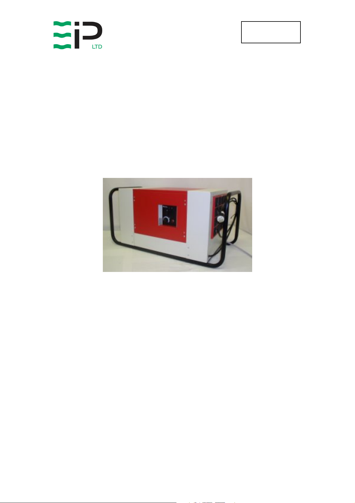
K100P
DEHUMIDIFIER
OWNER’S MANUAL
www.eipl.co.uk
Page 1 of 16
Page 2

Drawing : - TPC304
Issue : - 8
Date : - 10/12/13
K100P
PACKAGE CONTENTS
Item Description Quantity
10241HZ-US Dehumidifier 1 off
3086144 Quick release hose coupling 1 off
3944110 PVC Tube – 3/8” I/D 7.8M
TPC304 Manual 1 off
Page 2 of 16
Page 3

Drawing : - TPC304
Issue : - 8
Date : - 10/12/13
INTRODUCTION
Dehumidifiers remove moisture from the air that is circulating through the unit.
The resulting reduction of relative humidity helps prevent rust, rot, mold,
mildew and condensation within the room, or other enclosed spaces where
the dehumidifier is used.
A dehumidifier consists of a motor-compressor unit, a refrigerant condenser,
an air circulating fan, a refrigerated surface, a means of collecting and
disposing the condensed moisture and a cabinet to house these components.
The fan draws air through the refrigerated surface and cools it below its dew
point, removing moisture which is collected and led away. The cool air then
passes the hot condenser, where it is reheated. With the addition of other
radiated heat the air is discharged into the room at a higher temperature but
lower relative humidity than when the air entered the unit. Continuous
circulation of the room air through the dehumidifier unit gradually reduces the
relative humidity in the room.
The K100PPPP dehumidifier is a rugged reliable drying unit designed to
operate effectively over a broad range of temperature and humidity
conditions. A powerful and reliable active hot gas defrost system, controlled
by an electronic timer, guarantees positive de-icing and thereby optimizing
operation at low temperatures.
The unit incorporates a welded steel chassis and is finished in vinyl coated
steel covers for resilience to damage caused by rough handling.
Page 3 of 16
Page 4

Drawing : - TPC304
Issue : - 8
Date : - 10/12/13
SPECIFICATIONS
M
ODEL
:
10241HZ-US
H
EIGHT
: 17” (431mm)
W
IDTH
: 28” (711mm)
D
EPTH
: 18” (457mm)
W
EIGHT
: 138 Lbs (62Kg)
A
IRFLOW
P
OWER SUPPLY
P
F
R
EFRIGERANT TYPE/QTY
O
PTIONAL EXTRAS
: 700 CFM (1190 M3/Hr)
: 110V 1Ph 60Hz
OWER
INISH
1090 W (max)
: Epoxy coated steel
10241HZ-US – R407C (540g)
:
10241HC-US - R407C (540g)
:
• Trolley
• Wall Mount Bracket
"This product contains fluorinated greenhouse gases covered by the Kyoto Protocol. The
refrigeration system is hermetically sealed.
The Global Warming Potential (GWP) of refrigerants used in products manufactured by Ebac
Industrial Products Ltd is as follows
R134a – 1300
R407c – 1610
For type and weight of refrigerant contained in this unit, please refer to the product data label"
Page 4 of 16
Page 5

Drawing : - TPC304
Issue : - 8
Date : - 10/12/13
INSTALLATION
POSITIONING:
Position the dehumidifier unit in the center of the room to be conditioned if at
all possible. However if a damp patch is particularly apparent the outlet grille
should be pointed towards it.
NOTE: Both inlet grille and outlet grille of the dehumidifier unit must have
clear space around them and not be obstructed in anyway.
WIRING:
Connect the power mains cable to a designated 30 Amp breaker. As follows:-
For Models without plugs:-
Brown Live
Blue Neutral
Green/Yellow Earth (ground)
DRAINAGE:
Connect a 3/8” inside diameter hose to the water outlet pipe. Secure the hose
using a worm drive clip. The hose should at no point be raised higher than the
outlet pipe. Failure to observe this requirement will result in flooding of the
dehumidifier unit.
The K100P has a water pump fitted as standard which is capable of
discharging the condensate water 20ft vertical lift away from the unit & 100ft
horizontal. The water can, therefore, be discharged into a drain some distance
away.
Page 5 of 16
Page 6

Drawing : - TPC304
WARNING:
Issue : - 8
Date : - 10/12/13
OPERATION
The operation of the dehumidifier is to remove moisture from the air by having
it condense on the cold tubes of the evaporator coil. The air then passes over
the hot condenser coil and returns to the conditioned space slightly warmer
and dryer than when it entered the dehumidifier unit. To concentrate drying all
doors and windows should be kept closed.
Test for Correct Operation
Remove the cover by releasing the retaining bolts and follow the test
procedure laid out below:-
DO NOT RUN THE MACHINE WITHOUT THE COVERS IN
PLACE FOR ANY LONGER THAN NECESSARY. DO NOT
REMOVE / REPLACE THE COVERS WITH THE POWER ON
1. Set the adjustable humidistat to maximum.
2. Switch the machine to the on position, this will result in the compressor
starting to run and the fan blade starting to rotate.
3. When the compressor has been running for 20 minutes the coils located
above the drain tray will be evenly coated in frost. (If the ambient
temperature is above 77ºF the coils will be covered in water.)
4. After the machine has been running for approximately 50 minutes the unit
will automatically enter into defrost. The defrost cycle lasts for
approximately 3 minutes, this will result in the frost on the coils melting and
dripping into the drainage tray.
5. After the defrost has finished the machine will return to normal operation.
6. Ensure the condensate drains away from the machine.
Setting the Adjustable Humidistat
The position of the humidistat depends on the application the K100PPP is
being used for and the conditions within the area to be dried. The worse the
conditions within the area then the higher the humidistat should be set (i.e. the
machine will run for a longer period of time to ensure all the moisture is
reduced sufficiently). As a rough guide the humidistat wants to be set at
approximately 50% for factories and warehouses, and for basements or deflooding then the humidistat should be set to approximately 100%.
Page 6 of 16
Page 7

Drawing : - TPC304
Issue : - 8
Date : - 10/12/13
Discharge Pump
The pump works automatically and periodically pumps away collected
moisture to a drain or container. The pump is capable of discharging water to
a vertical height of 20ft.
Indicator Panel
The K100P is fitted with an indicator lamp to show when power is available
and the unit is switched on, if this does not appear to be functioning correctly
then refer to the repairs section.
Warnings.
• Due to the high pressures within the refrigeration circuit, under no
circumstances must direct heat be applied to the evaporator coil in an
attempt to remove the build up of ice.
• No attempt should be made to cut open any part of the refrigeration circuit
due to high pressures and gas involved.
• If the unit is switched off at the mains power supply for any reason, the unit
must be allowed to stand at rest for at least three minutes before
restarting.
Page 7 of 16
Page 8

Drawing : - TPC304
WARNING:
WARNING:
Issue : - 8
Date : - 10/12/13
ROUTINE MAINTENANCE
To ensure continued full efficiency of the dehumidifier, maintenance
procedures should be performed as follows:
Removal of the cover is achieved by means of four screws at the sides of the
unit at base level. With the cover removed all maintenance can be carried out.
1. Clean the surface of the evaporator and condenser coils by blowing the
dirt out from behind the fins with compressed air. Hold the nozzle of the air
hose away from the coil (approx 6”) to avoid damaging the fins.
Alternatively, vacuum clean the coils.
ENSURE THAT THE POWER CORD TO THE MACHINE HAS BEEN
DISCONNECTED BEFORE CARRYING OUT ROUTINE MAINTENACE ON
ITEMS 1, 2, 3, AND 4.
DO NOT STEAM CLEAN REFRIGERATION COILS
2. Check that the fan is firmly secured to the motor shaft and that the
fan rotates freely.
THE FAN IS SEALED FOR LIFE AND DOES NOT NEED LUBRICATING.
3. To check the refrigerant charge, run the unit for 20 minutes (with
humidistat set to maximum) and briefly remove the cover. The
evaporator coil should be evenly frost coated across its surface. At
temperatures above 77°f, the coil may be covered with droplets of
water rather than frost. Partial frosting accompanied by frosting of
the thin capillary tubes, indicates loss of refrigerant gas or low
charge.
4. Check all wiring connections.
I
F ANY OF THE PRECEDING PROBLEMS OCCUR, CONTACT THE EBAC
S
ERVICE CENTER PRIOR TO CONTINUED OPERATION OF THE UNIT TO
PREVENT PERMANENT DAMAGE
.
Page 8 of 16
Page 9

Drawing : - TPC304
Issue : - 8
Date : - 10/12/13
REPAIRS
1. Should an electrical component fail, consult the Factory Service
Center to obtain the correct replacement part.
2. If refrigerant gas is lost from the machine, it will be necessary to use
a refrigeration technician to correct the fault. Contact the Factory
Service Center prior to initiating this action.
Any licensed refrigeration technician will be able to service the
equipment. The following procedure must be used:
a. The source of the leak must be determined and corrected.
b. The machine should be thoroughly evacuated before
recharging.
c. The unit must be recharged with refrigerant measured
accurately by weight.
d. For evacuation and recharging of the machine, use the crimped
and brazed charging stub attached to the side of the refrigerant
compressor.
The charging stub should be crimped and rebrazed after
servicing. N
any part of the circuit. Service valves may leak causing further
loss of refrigerant gas.
3. The refrigerant compressor fitted to the dehumidifier is a durable
unit that should give many years of service. Compressor failure can
result from the machine losing its refrigerant gas. The compressor
can be replaced by a licensed refrigeration technician.
Failure of the compressor can be confirmed by the following
procedure:
a. Establish that power is present at the compressor terminals
using a voltmeter.
b. With the power disconnected, check the continuity of the internal
winding by using meter across the compressor terminals. An
open circuit indicates that the compressor should be replaced.
c. Check that the compressor is not grounded by establishing that
a circuit does not exist between the compressor terminals and
the shell of the compressor.
EVER
allow permanent service valves to be fitted to
Page 9 of 16
Page 10

Drawing : - TPC304
S
C
R
Issue : - 8
Date : - 10/12/13
TROUBLESHOOTING
YMPTOM
Little or no airflow
Little or no water
extraction
Little or no defrost
when required
1. Loose fan on shaft
2. Fan motor burnt out
3. Dirty refrigeration coils
4. Loose electrical wiring
1. Insufficient air flow
2. Compressor fault
3. Loss of refrigerant gas
1. Faulty Timer
2. Faulty bypass timer
AUSE
EMEDY
1. Tighten fan
2. Replace the fan motor
3. See Routine Maintenance
Section
4. Check the wiring diagram
to find fault and repair
1. Check all of the above
2. Contact the Factory
Service Center
3. Contact the Factory
Service Center
1. Contact the Factory
Service Center
2. Contact the Factory
Service Center
Unit vibrates
excessively
Water flooding inside
machine
1. Loose compressor
mounts
2. Damaged fan
1. Faulty water pump
2. Sticking float switch
3. Drain tray blocked
1. Tighten nuts on
compressor mounts
2. Replace with a new fan
1. Replace water pump
2. Remove obstruction
3. Remove obstruction
Spare parts available online
www.EIPLDIRECT.com
Page 10 of 16
Page 11

Drawing : - TPC304
Issue : - 8
Date : - 10/12/13
K100P
SPARE PARTS LIST
P
ART
Q
N
UMBER
D
ESCRIPTION
N
UMBER
UANTITY
1 DEFROST TIMER 1600500
2 CAPILLIARY TUBE .047 2pcs. 3014251
3 *COMPRESSOR (R22) 3020116
3 *COMPRESSOR (R407c) 3944915
4 CONDENSER COIL 3020727
5 EVAPORATOR COIL 3020732
6 DEFROST VALVE 3020810
7 FILTER DRYER 3020904
8 CONTACTOR 3030373
9 SOLENOID COIL 3030420
10 ROTARY SWITCH 3030512
11 INDICATOR LAMP 3032203
12 HUMIDISTAT 3035145
13 MOTOR 3035774
1
48” x2
1
1
1
1
1
1
1
1
1
1
1
1
14 CAPACITOR 3036337
15 CLAW LATCH 3083508
16 USA PLUG 3934515
17 AXIAL FAN 3940002
18 FILTER MEDIA 2027114
19 GFI PLUG 3934517
20 PUMP 3160145
*COMPRESSOR – Please check the serial Number plate in order to confirm correct model
(10241HZ-US = R22, 10241HC-US = R407c
1
2
1
1
1
1
1
Page 11 of 16
Page 12

Drawing : - TPC304
PLEASE NOTE
WARRANTY REGISTRATION
Issue : - 8
Date : - 10/12/13
LIMITED WARRANTY
Our products carry a one-year unconditional warranty against any defects in
workmanship or material. This warranty will cover all parts and labor required
to repair your Ebac product. This warranty is invalid if the unit has been
abused, damaged, whether intentional or accidental, or if any modifications
have been made to the unit.
THE FOREGOING WARRANTY IS EXCLUSIVE AND IS ISSUED IN LIEU OF
ALL OTHER WARRANTIES (WHETHER WRITTEN, ORAL, OR IMPLIED)
INCLUDING THE WARRANTY OF MERCHANTABILITY AND THE
WARRANTY OF FITNESS FOR A PARTICULAR PURPOSE. EBAC
INDUSTRIAL PRODUCTS, INC. DISCLAIMS ANY LIABILITY FOR
CONSEQUENTIAL DAMAGES, LOST PROFITS, OR INCIDENTAL
DAMAGES FOR BREACH OF ANY WRITTEN OR IMPLIED WARRANTY
WITH RESPECT TO THE FOREGOING DESCRIBED MERCHANDISE.
For Your Records: Model:____________________
S/N:______________________
Date Received:______________
SAVE THIS SECTION FOR YOUR RECORDS
CLIP AND RETURN THIS CARD
To ensure that your
Ebac Dehumidifier is
accorded the full
coverage provided by
this warranty, please
complete and mail this
card at your earliest
convenience.
DATE
MODEL ___________ S/N ________________ RECEIVED ________________
OWNER __________________________________________________________
ADDRESS ________________________________________________________
CITY __________________________ STATE ________ ZIP _______________
COMMENTS ______________________________________________________
_________________________________________________________________
Thank You
Page 12 of 16
700 Thimble Shoals Boulevard, Suite 109, Newport News, Virginia. 23606-2575
Ebac Industrial Products.
Page 13

Drawing : - TPC304
Issue : - 8
Date : - 10/12/13
Page 13 of 16
Page 14

Drawing : - TPC304
Issue : - 8
Date : - 10/12/13
Page 14 of 16
Page 15

Drawing : - TPC304
Issue : - 8
Date : - 10/12/13
Page 15 of 16
Page 16

Drawing : - TPC304
UK Head Office
American Sales Office
German Sales Office
Issue : - 8
Date : - 10/12/13
Ebac Industrial Products Ltd
St Helens Trading Estate
Bishop Auckland
County Durham
DL14 9AD
Tel: +44 (0) 1388 664400
Fax: +44 (0) 1388 662590
www.eipl.co.uk
sales@eipl.co.uk
Page 16 of 16
Ebac Industrial Products Inc
700 Thimble Shoals Blvd.
Suite 109, Newport News
Virginia, 23606-2575
Tel: +01 757 873 6800
Fax: +01 757 873 3632
www.ebacusa.com
sales@ebacusa.com
USA
Ebac Industrial Products Ltd.
Gartenfelder Str. 29-37
Gebäude 35
D-13599, Berlin
Germany
Tel: +49 3043 557241
Fax: +49 3043 557240
www.eip-ltd.de
sales@eip-ltd.de
 Loading...