

Page 1

Drawing : - TPC 393
Issue : - 5
Date : - 28/04/14
DD1200
10541GR-US – 460V / 3PH / 60HZ
INDUSTRIAL DEHUMIDIFIER
OWNER’S MANUAL
www.eipl.co.uk
Page 2

Drawing : - TPC 393
Issue : - 5
Date : - 28/04/14
DD1200
PACKAGE CONTENTS
Item Description Quantity
10541GR-US Dehumidifier 1
TPC393 Manual 1
Page 3

Drawing : - TPC 393
Issue : - 5
Date : - 28/04/14
UNPACKING
Carefully remove the DD1200 dehumidifier unit from its transit box and
visually check for signs of transit damage. If there is evidence of damage DO
NOT attempt to operate the unit, call your supplier for advice. Do not discard
the packing, it will be useful when transporting the dehumidifier unit in the
future.
INTRODUCTION
Dehumidifiers remove moisture from the air that is circulating through the unit.
The resulting reduction of relative humidity helps prevent rust, rot, mould,
mildew and condensation within the room, or other enclosed spaces where
the dehumidifier is used.
The DD1200 is of the desiccant wheel type designed to dry air by passing a
large volume of air, the “process” air through a slowly rotating Silica gel rotor.
Silica gel is a hygroscopic material that absorbs moisture direct from the air.
As the air passes through the rotor the humidity of the air is reduced, whilst
the moisture content of the rotor is increased. A smaller volume of air, the
reactivation air, is heated by an internal heater and passes through a portion
of the rotor in the opposite direction. As this heated air passes through the
rotor it will “reactivate” it by removing the moisture content from the silica gel
material. The reactivation air will leave the humidifier as warm, moist air and
must be vented to outside of the building.
Continuous circulation of the room air through the dehumidifier unit gradually
reduces the relative humidity in the room.
The DD1200 dehumidifier is a robust, compact unit designed to control the
humidity in the enclosed space in which it is placed. The casing is fabricated
from Steel then painted and has been designed for the exacting conditions
which can prevail in offices, shops, houses, restaurants, public houses etc. It
combines compactness with high reliability and strength
The unit is thermally protected and will automatically switch off in excessive or
abnormal conditions.
The dehumidifier has two separate filters. One in the “process” air inlet and
one in the “reactivation” air inlet, used to clean the air entering the
dehumidifier.
Page 4

SPECIFICATIONS
MODEL: DD1200
HEIGHT: 1420mm (56”)
WIDTH: 711mm (28”)
DEPTH: 584mm (23”)
WEIGHT: 105Kg (231.5lbs)
POWER SUPPLY: 460V, 3 ph, 60Hz
POWER 11.8 kW (max)
F1 CONTROLS FUSE 2A 250V 5x20 Cartridge fuse
PROCESS AIRFLOW MAXIMUM: 1500m3/hr (883 cfm)
PROCESS AIRFLOW NOMINAL: 1200m3/hr (705cfm)
Drawing : - TPC 393
Issue : - 5
Date : - 28/04/14
REGENERATION AIRFLOW NOMINAL: 330m3/hr (195 cfm)
PROCESS AIR OUTLET DIA: 200mm (8”)
REGENERATION AIR OUTLET DIA: 150mm (6”)
ROTOR WHEEL SPEED: 13.6 (RPH)
ROTOR SIZE DIA X DEPTH: 450mm (17.7”) x 200mm (7.9”)
HIGH EXTRACTION SETTING
266 l/day (562 ppd)
@ 27°C 60% RH:
HIGH EFFICIENCY SETTING
190 l/day (402 ppd)
@ 27°C 60% RH:
DEEP DRYING SETTING
241 l/day (508 ppd)
@ 27°C 60% RH:
TYPICAL DRY AIR OFF
9
HIGH EXTRACTION SETTING (%RH)
TYPICAL DRY AIR OFF
12
HIGH EFFICIENCY SETTING (%RH)
TYPICAL DRY AIR OFF
5
DEEP DRYING SETTING (%RH)
MINIMUM OPERATING TEMPERATURE: -20°C (-4°F)
MAXIMUM OPERATING TEMPERATURE 40°C (104°F)
Page 5
Drawing : - TPC 393
Issue : - 5
Date : - 28/04/14
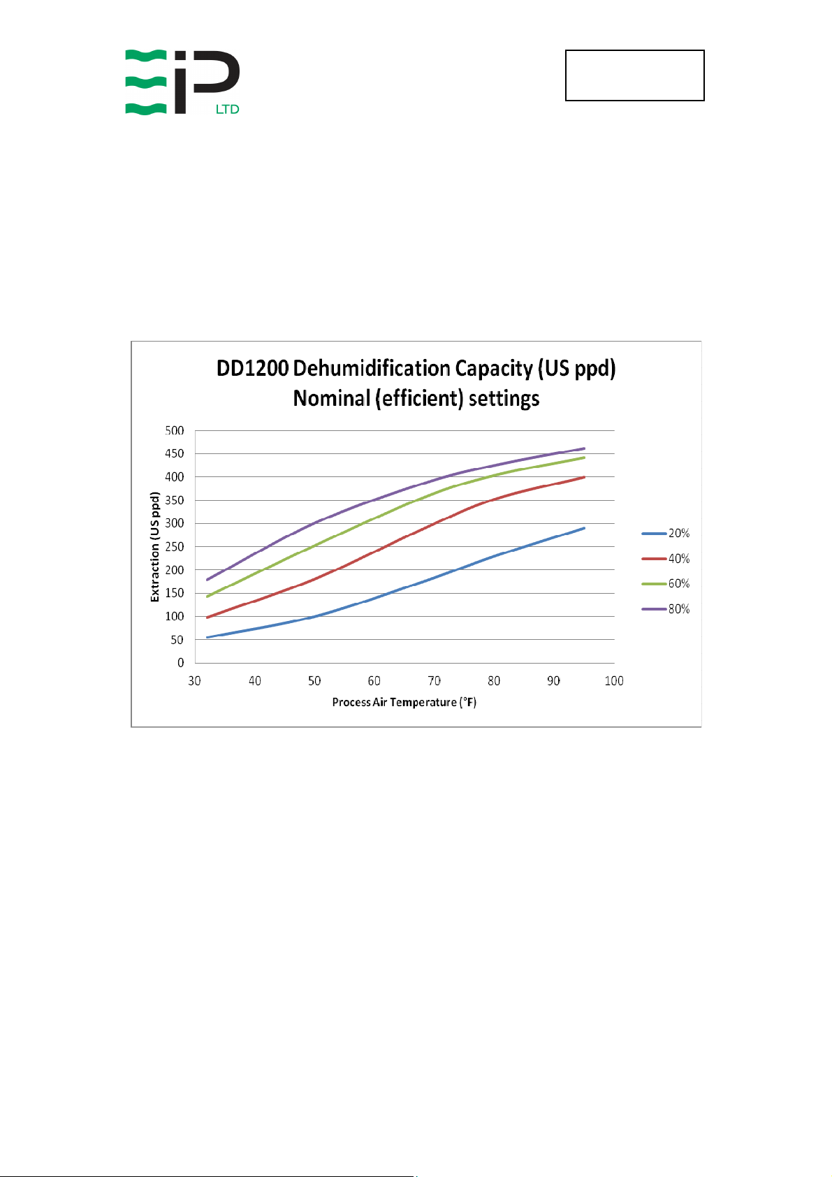
UNIT CAPACITY
The ambient conditions of the area to be dehumidified will determine the
amount of water extraction the unit is capable of.
Measure the ambient conditions of the area to be determined and then use
that information with the following capacity diagram to determine the unit
capacity.
Page 6
Drawing : - TPC 393
-
WARNING
Issue : - 5
Date : - 28/04/14
INSTALLATION
The DD1200 is designed for indoor use. The unit should be placed on a level
surface and a space of 1 meter free around all faces to allow access for any
duct work and servicing.
Connecting duct work:
The regeneration outlet must be ducted to outside the area being
dehumidified. The outlet duct spigot is 6” diameter and only 6” ducting or
greater should be attached.
The process outlet can be ducted to a specific area or another room. The
outlet duct spigot is 8” diameter and only 8” ducting or greater should be
attached.
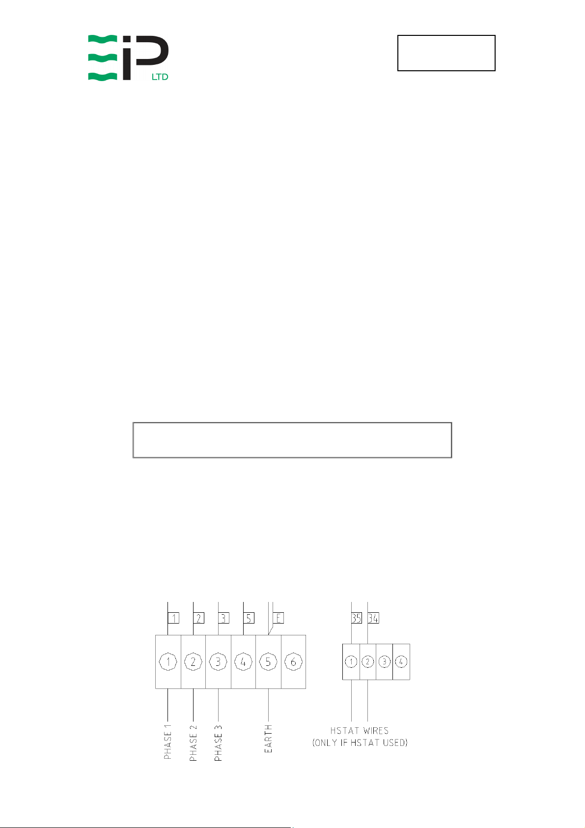
Power Supply & Humidistat Control:
The unit must be connected to a suitable 460V, 3 phase, 60Hz supply.
THIS APPLIANCE MUST BE EARTHED
Feed power cables through the gland provided and then wire the unit as
shown below.
An external humidistat can also be used to control the relative humidity in the
dehumidified area. If a humidistat is used then the wires should pass through
the gland provided and then wired as below.
-
Page 7

Drawing : - TPC 393
PROCESS AIR
REGEN AIR
TEMPERATURE
STANDARD
HIGH
DEEP DRYING
Issue : - 5
Date : - 28/04/14
Control Settings
Once the unit is positioned correctly, required duct work attached and the
power supply connected, the fan speeds and temperature control need to be
set correctly.
The fan speed controls are located behind a removable cover, to the right of
the main controls. The controls are numbered 1 to 10, with 10 being the
maximum speed.
The temperature control regulates the temperature of the reactivation airflow
onto the desiccant wheel. The control can be set up to a maximum of 145°C
To adjust the temperature control simply press and hold the UP or DOWN
arrows until the required temperature is selected. Once the required set point
is reached release the buttons and the value is stored.
For normal (efficient) operation the process airflow should be set to 705cfm,
and the regeneration airflow set to 195cfm. Measurements should be taken at
the duct outlets using a suitable instrument.
The temperature setting should be set to 90°C above the ambient
temperature of the area being dehumidified
If high moisture extraction is required it will be necessary to increase both the
process and regeneration airflows. The temperature control setting should
also be increased.
If very low humidity levels are required then the process airflow should be
reduced.
The following table should be used as a guide:
FLOW
(CFM)
FLOW
(CFM)
RISE
(K)
(EFFICIENT)
EXTRACTION
(LOW RH)
705 195 90
824 235 110
589 235 110
Page 8

Drawing : - TPC 393
Issue : - 5
Date : - 28/04/14
FAN PERFORMANCE CURVES
For example:
If the total system resistance is 600pa then the process fan selector would
have to be set to No 10 to achieve the required airflow of 705cfm
For example:
If the total system resistance is 400pa then the regen fan selector would have
to be set to No 8 to achieve the required airflow of 195cfm
Page 9

Drawing : - TPC 393
M
0
Issue : - 5
Date : - 28/04/14
OPERATION
The electrical controls are located on the front of the unit. They are:
• On / Off Switch
Dehumidifier in continuous operation
A
Dehumidifier operation by means of an external
humidistat
Dehumidifier OFF
• An hour counter is provided to display the total time the unit has been
in operation
• DRYING lamp – unit is in drying mode.
• HEATING lamp – indicates heating elements are on. Cycle on/off when
in drying mode.
• FAULT lamp – unit has a fault
To start the dehumidifier, turn the On / Off switch to position M.
After a slight delay the fans will operate – air can be felt blowing from the air
outlets and the heater will come on.
The unit will operate continuously at this setting.
If an external humidistat control is fitted, turn the unit to switch to position A.
Depending on the setting of the humidistat, the dehumidifier may switch off as
the relative humidity in the room decreases. As the humidity increase the unit
will automatically switch back on.
High Temperature Cut-Out:
The DD1200 dehumidifier has been designed to work in ambient conditions of
-4ºF to +104ºF. Should the temperature in the room become excessive an
overheat protector will operate, switching off the heaters. The fans and drive
motor will continue to operate but the fault lamp will illuminate. Prior to
resetting the protector, check that the dehumidifier is installed correctly and
the ambient temperature does not exceed 104°F.
See repairs section for details on resetting device.
Page 10

Drawing : - TPC 393
Issue : - 5
Date : - 28/04/14
SAFETY
-WARNING-
♦ DO NOT ALLOW CHILDREN TO PLAY WITH OR AROUND THE
UNIT. ENSURE THE UNIT IS INACCESIBLE TO CHILDREN
WHEN NOT ATTENDED.
♦ DO NOT USE THIS UNIT IN AN ENVIRONMENT CONTAINING
FLAMMABLE FUMES
♦ DO NOT USE THIS UNIT IF THE CABINET OR POWER CORD IS
DAMAGED
♦ DO NOT INSERT OBJECTS INTO ANY OF THE GRILLES ON
THE MACHINE
♦ DO NOT COVER OR OBSTRUCT AIRFLOW FROM THE
GRILLES
♦ DO NOT OPERATE THE UNIT WITH THE COVERS REMOVED
♦ DO NOT ATTEMPT ANY REPAIRS SHOULD THE UNIT FAIL TO
OPERATE
♦ DO NOT STAND ON THE UNIT
♦ DO NOT LIFT THE UNIT WHEN SWITCHED ON
♦ DO CHECK THE PLUG ON THE EQUIPMENT MATCHES THE
SUPPLY
♦ DO USE THE UNIT FOR THE PURPOSE FOR WHICH IT WAS
DESIGNED
♦ DO ENSURE THE POWER CORD AND SUPPLY IS EARTHED
CORRECTLY
♦ DO USE A RESIDUAL CURRENT DEVICE “RCD” WHERE
POSSIBLE
♦ DO KEEP THE UNIT DRY. NEVER USE A HOSE OR PRESSURE
WASHER TO CLEAN THE UNIT.
Page 11

Drawing : - TPC 393
WARNING:
Issue : - 5
Date : - 28/04/14
ROUTINE MAINTENANCE & REPAIR
To ensure continued full efficiency of the dehumidifier, maintenance
procedures should be performed as follows:
ENSURE THAT THE POWER CORD TO THE MACHINE HAS
BEEN DISCONNECTED BEFORE CARRYING OUT ROUTINE
MAINTENACE.
SWITCH OFF THE DEHUMIDIFIER APPROXIMATELY 15
MINUTES PRIOR TO REMOVING ANY PANELS, ALLOWING
THE HEATER TO COOL DOWN
• We recommend that the filters are checked at least once a month.
Intervals for cleaning or replacement of filters will depend on the
installation
• Never operate the dehumidifier without the filters, as the rotor can be
damaged by dust.
To carryout the following, it is necessary to remove the side panels.
This machine should be serviced by qualified Ebac Industrial Products Ltd
personnel or other persons having technical competence in servicing
electrical equipment following the instructions in this Service Manual.
• The rotor is maintenance free. However, should it be necessary to
clean the rotor, compressed air should be used to carefully blow dirt
from the rotor.
• The heaters are maintenance free. However should it be necessary to
clean the heaters, compressed air should be used to carefully blow dirt
from the heaters.
• Check that the fans are firmly secured and that the fan rotates freely.
• Check all wiring connections.
• Check the belt tensioning at regular intervals.
• The overheat protector is located inside the unit, below the desiccant
wheel. To reset this device press the red button.
• Should an electrical component fail, consult the Factory Service Center
to obtain the proper replacement part.
Page 12

Drawing : - TPC 393
Issue : - 5
Date : - 28/04/14
IF ANY OF THE PRECEDING PROBLEMS OCCUR, CONTACT THE EBAC
INDUSTRIAL PRODUCTS LTD SERVICE CENTER PRIOR TO CONTINUED
OPERATION OF THE UNIT TO PREVENT PERMANENT DAMAGE
TROUBLESHOOTING
SYMPTOM
CAUSE
REMEDY
.
Little or no
dehumidification
capacity
Dehumidifier does
not start
Rotor does not
rotate
No Dry or Wet Air
Airflow
Filter clogged
No regeneration heat Check Heaters / OHP
Reduced airflow Check fans / duct
No rotation of Rotor Check belt tension / drive motor
Air leakage Check sealing
No power Check fuse
Correct switch setting Check Auto / Manual switch
Loose electrical wiring
Drive belt slipping Check belt tension
Drive belt broken Replace drive belt
Rotor jammed Check centre shaft, rim of rotor
Drive motor faulty Check supply /Replace motor
Filter clogged Clean or replace filters
Fan faulty Check supply / fan
Ducts blocked Check duct for obstruction
Clean or replace filters
Check wiring diagram - fault
find & repair
Fan loose Check fans secured firmly
Noisy
Loose fastenings Tighten all fastenings
Page 13

Drawing : - TPC 393
Issue : - 5
Date : - 28/04/14
Page 14

1
3
OF
SHEET
1/10
1
W DAGLISH
1
DD1200
DRG.NO.
DRAWN :
CAD SCALE :
N/A
N/A
DD1200 - GENERAL ASSEMBLY / OVERV IEW
2
AIR INLET
PROCESS
1 12/02/13 ORIGINAL
ISS. DATE COMMENTS
450
3
65
450
4
1
0
3
AIR INLET
REGENERATION
314
133
2
6
8
3
2
3
5
6
TITLE
MATERIAL
DD
D
NN
ND
AA
AN
LL
LA
KK
KL
CC
CK
MM
M
UU
UC
AA
AM
AA
AU
HH
HA
DD
D
A
RR
RH
NN
ND
PP
P
UU
UR
AA
AN
OO
OP
DD
DU
LL
LA
HH
HO
D
..
.
GG
GL
SS
SH
II
IS
oo
o.
NN
NG
B
C
E
BB
BI
CC
Co
EE
EN
DIMENSIONS IN m.m.
OTHERWISE STATED
TOLERANCES UNLESS
77
7
99
97
3RD ANGLE PROJECTION
99
99
1
11
19
4
2
FINISH
1
0.25
0.5 DEGREE
0.05
ANGULAR
0.0
0.00
0.
DO NOT SCALE
IF IN DOUBT ASK
3
4
CONTROLS
40
5
150
n
AIR OUTLET
6
REGENERATION
40
5
ELECTRICAL
CONNECTIONS
POWER
ISOLATOR
200
n
OUTLET
PROCESS AIR
PANEL
MAINS INLET GLAND
WIRING GLAND
HUMIDISTAT SENSOR
580
290
6
7
4
0
1
7
1
126
.
.
1
7
D D
C C
B B
A A
Page 15

2
3
OF
SHEET
1/14
1
W DAGLISH
1
DD1200
DRG.NO.
DRAWN :
CAD SCALE :
N/A
N/A
DD1200 - GENERAL ASSEBLY / OVERVIEW
2
1 12/02/13 ORIGINAL
ISS. DATE COMMENTS
3
TITLE
MATERIAL
DD
D
NN
ND
AA
AN
LL
LA
KK
KL
CC
CK
MM
M
UU
UC
AA
AM
AA
AU
HH
HA
DD
D
A
RR
RH
NN
ND
PP
P
UU
UR
AA
AN
OO
OP
DD
DU
LL
LA
HH
HO
D
..
.
GG
GL
SS
SH
II
IS
oo
o.
NN
NG
B
C
E
BB
BI
CC
Co
EE
EN
DIMENSIONS IN m.m.
OTHERWISE STATED
TOLERANCES UNLESS
77
7
99
97
3RD ANGLE PROJECTION
99
99
1
11
19
4
2
FINISH
1
0.25
0.5 DEGREE
0.05
ANGULAR
0.0
0.00
0.
DO NOT SCALE
IF IN DOUBT ASK
3
4
5
6
D D
C C
B B
A A
5
6
Page 16

3
3
OF
SHEET
1/10
1
W DAGLISH
1
DD1200
DRG.NO.
DRAWN :
CAD SCALE :
N/A
N/A
DD1200 - GENERAL ASSEMBLY / OVERV IEW
2
1 12/02/13 ORIGINAL
ISS. DATE COMMENTS
DETAIL A
SCALE 1/3
3
TITLE
MATERIAL
DD
D
NN
ND
AA
AN
LL
LA
KK
KL
CC
CK
MM
M
UU
UC
AA
AM
AA
AU
HH
HA
DD
D
A
RR
RH
NN
ND
PP
P
UU
UR
AA
AN
OO
OP
DD
DU
LL
LA
HH
HO
D
..
.
GG
GL
SS
SH
II
IS
oo
o.
NN
NG
B
C
E
BB
BI
CC
Co
EE
EN
DIMENSIONS IN m.m.
OTHERWISE STATED
TOLERANCES UNLESS
77
7
99
97
3RD ANGLE PROJECTION
99
99
1
11
19
4
2
FINISH
1
0.25
0.5 DEGREE
0.05
ANGULAR
0.0
0.00
0.
DO NOT SCALE
IF IN DOUBT ASK
3
4
5
A
6
D D
C C
B B
A A
5
6
Page 17

Page 18

Page 19

Page 20

Drawing : - TPC 393
UK Head Office
America
n Sales Office
German Sales Office
Issue : - 5
Date : - 28/04/14
Ebac Industrial Products Ltd
St Helens Trading Estate
Bishop Auckland
County Durham
DL14 9AD
Tel: +44 (0) 1388 664400
Fax: +44 (0) 1388 662590
www.eipl.co.uk
sales@eipl.co.uk
Ebac Industrial Products Inc
700 Thimble Shoals Blvd.
Suite 109, Newport News
Virginia, 23606-2575
Ebac Industrial Products Ltd.
Gartenfelder Str. 29-37
Gebäude 35
D-13599, Berlin
USA
Tel: +01 757 873 6800
Fax: +01 757 873 3632
www.ebacusa.com
sales@ebacusa.com
Tel: +49 3043 557241
Fax: +49 3043 557240
www.eip-ltd.de
sales@eip-ltd.de
Germany
 Loading...