

Page 1
CD200
OWNERS MANUAL
Date :-
10/12/13
Drawing No. :- TPC364
Issue :- 7
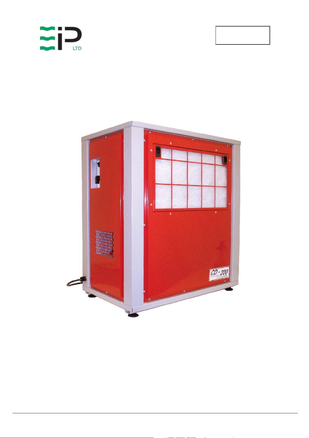
EBAC MODEL CD200
INDUSTRIAL DEHUMIDIFIER
OWNER’S MANUAL
Ebac Industrial Products, Inc.
700 Thimble Shoals Blvd, Suite 109
Newport News, VA. 23606-2575
Tel: (757) 873 6800 Fax: (757) 873 3632
Website www.ebacusa.com
Page 2

CD200
OWNERS MANUAL
Date :-
10/12/13
UNIT
UNIT
UNITUNIT
PACKAGE CONTENTS
PACKAGE CONTENTS
PACKAGE CONTENTSPACKAGE CONTENTS
Item Description Quantity
10182GR-US Dehumidifier 1
3086144 Quick release hose coupling 1
3944110 PVC Tube – 3/8” I/D 1
Drawing No. :- TPC364
Issue :- 7
3035832 Free issue socket 1
TPC364 Manual 1
Page 3

CD200
OWNERS MANUAL
Date :-
10/12/13
Drawing No. :- TPC364
Issue :- 7
UNPACKING
Carefully remove the CD200 dehumidifier unit from its transit packaging and visually check for
signs of transit damage. If there is evidence of damage DO NOT attempt to operate the unit, call
your supplier for advice. Do not discard the packing, it will be useful when transporting the
dehumidifier unit in the future.
INTRODUCTION
The Ebac CD200 industrial dehumidifier removes moisture from the air through the refrigeration
process.
The Ebac CD200 is basically comprised of:
1) A compressor
2) A refrigerant evaporator coil
3) A refrigerant condenser coil
4) One circulation fan
5) A humidistat
6) A condensate pump
7) A cabinet to house the above components
The fan draws the moist air through the cold evaporator coil which cools the air below its dew
point. Moisture forms on the evaporator coil and is collected in the condensate tray which is
equipped with a permanent drain. The cooled air then passes through the hot condenser coil
where it is reheated using the same energy removed during the cooling phase, plus the additional
heat generated by the compressor. The air is therefore discharged from the dehumidifier at a
slightly higher temperature with a lower absolute humidity than with which it entered.
Continuous circulation of air through the dehumidifier gradually reduces the relative humidity
within the area.
The CD200 dehumidifier is a rugged, reliable drying unit designed to operate effectively over a
broad range of temperature and humidity conditions.
The CD200 dehumidifier uses an adjustable humidistat to enable you to select the level of
dryness.
Page 4

CD200
OWNERS MANUAL
Date :-
10/12/13
SPECIFICATIONS
MMMM
ODEL
ODEL
::::
ODELODEL
HHHH
EIGHT
EIGHT
::::
EIGHTEIGHT
WWWW
IDTH
IDTH
::::
IDTHIDTH
DDDD
EPTH
EPTH
::::
EPTHEPTH
Drawing No. :- TPC364
Issue :- 7
Ebac CD200
32.75” (832mm)
29.5” (745mm)
17.5” (445mm)
WWWW
AAAA
IRFLOW
IRFLOW
IRFLOWIRFLOW
POWER
POWER
POWERPOWER
PPPP
OWER
OWER
OWER OWER
FFFF
RRRR
EFRIGERANT
EFRIGERANT
EFRIGERANT EFRIGERANT
EIGHT
EIGHT
EIGHTEIGHT
SSSS
UPPLY
UPPLY
UPPLYUPPLY
INISH
INISH
INISHINISH
TTTT
::::
::::
::::
::::
YPE
YPE
YPEYPE
::::
/Q
/Q
/Q/Q
TY
TY
TYTY
176 lbs
Low 585 CFM
High 664 CFM
2250 W
220V/60Hz/1ph
Powder-coated Epoxy
::::
R407c
Page 5
CD200
OWNERS MANUAL
Date :-
10/12/13
Drawing No. :- TPC364
Issue :- 7
INSTALLATION
POSITIONING:
Position the dehumidifier unit in the center of the room to be conditioned if at all possible.
However if a damp patch is particularly apparent the outlet grille should be pointed towards it if
possible.
This unit can also be used in a duct system where applicable, please see the diagrams on the
following pages which identify the overall sizes of the unit and also the mounting points.
NOTE: Both inlet grille and outlet grille of the dehumidifier unit must have clear space around
them and not be obstructed in anyway.
This unit should be connected to a single outlet circuit fused spur with a 20A rating.
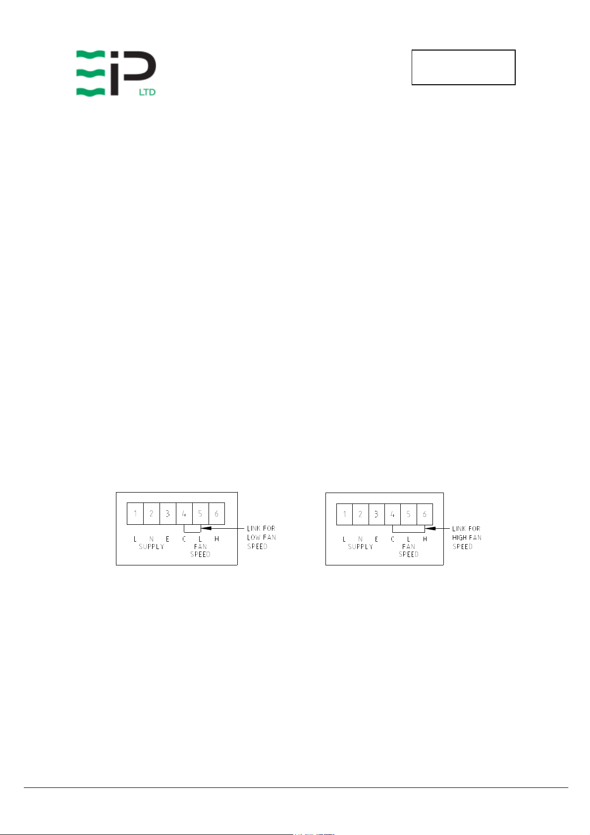
Selecting the correct fan speed – The CD200 has a low fan speed and a high fan speed and the
required speed must be chosen before installation. To select the correct fan speed firstly remove
the filter cover via the 9off screws, then remove the electrical box cover via the 4off M4 hex
head bolts. Once the electrical box cover is removed the supplied link wire must be wired
between either the ‘C’ and ‘L’ or the ‘C’ and ‘H’ terminals on the terminal block. This is shown
below. The default setting of the unit is high speed.
Page 6

CD200
OWNERS MANUAL
Date :-
10/12/13
Drawing No. :- TPC364
Issue :- 7
OPERATION
The following procedures should be followed to test the CD200 for correct operation:
1) After unpacking, examine all external features to confirm damage-free shipment. Report all
defects and damage at once. Connect the power cable to a grounded power source.
2) Install drain tubing as required (detailed in step F).
Caution: Do not operate the machine without the covers for any longer than necessary. Do
not remove/ replace the covers when the unit is in operation.
Check dehumidification process as follows:
A. Place unit on a level surface.
B. Start up unit as follows:
i.Ensure fan speed selection has been chosen as mentioned in previous pages.
ii.Rotate humidistat control knob to fully counter clockwise, minimum setting.
iii.Plug unit into power supply, switch unit on via on/off switch and rotate humidistat
knob clockwise to desired setting.
C. Check that the compressor is running.
D. Leave the machine running for 15 minutes.
E. Observe the evaporator coils behind the filter on the air inlet end of the unit to confirm
frost formation.
i.If the air temperature is below 70ºF, an even coating of frost should cover the entire
evaporator coil, except for the last one or two coils.
ii.If the air temperature is about 70ºF, frost and/or droplets of condensed water should
cover the entire evaporator coil.
F. As the drain tray fills, the condensate will automatically drain by gravity into the
condensate pump. Using the supplied hose fit one end to the drainage outlet and secure
and the other end of the hose must be located to a permanent drain. The pump has a lift
capacity of 5 meters therefore ensure the attached hose is no more than 5 meters above
the unit outlet point.
If after carrying out the above procedures, the unit does not appear to function properly, refer to
the Trouble Shooting section or contact the Factory Service Center.
WARNING:
• Due to the high pressures within the refrigeration circuit, under no circumstances must direct
heat be applied to the evaporator coil in an attempt to remove the build up of ice.
• No attempt should be made to cut open any part of the refrigeration circuit due to high
pressures and gas involved. If the unit is switched off at the mains power supply for any
reason, the unit must be allowed to stand at rest for at least five minutes before restarting.
Failure to do so may cause the unit to blow the fuses owing to the compressor due to there
being a refrigerant imbalance.
Page 7

CD200
OWNERS MANUAL
Date :-
10/12/13
Drawing No. :- TPC364
Issue :- 7
External Humidistat Option
The CD200 has the option of using an external humidistat remotely mounted within a room,
where available.
In the control box there is a connector that can be wired to, which will enable the use of an
external humidistat. The following steps should be carried out to enable correct operation of
the external humidistat.
• Locate the control box and remove the cover, keeping screws for re-attachment
• Locate the connector within the control box and remove the plug from the socket
• Dismantle the plug and remove the link wire from terminals 2 & 3
• Wire remote humidistat to terminals 1 & 3, ensuring wires pass through the plug back shell
• Re-assemble the plug and refit to the socket on the control box
• The CD200 internal humidistat will now be by-passed and the external humidistat will
control the unit.
Page 8

CD200
OWNERS MANUAL
Date :-
10/12/13
Drawing No. :- TPC364
Issue :- 7
ROUTINE MAINTENANCE
WARNING: ENSURE THAT THE POWER CORD TO THE MACHINE
HAS BEEN DISCONNECTED BEFORE CARRYING OUT
ROUTINE MAINTENANCE ON ITEMS 1, 2, 4, 5, AND 6.
To ensure continued full efficiency of the dehumidifier, maintenance procedures should be
performed as follows:
1. Clean the surface of the evaporator and condenser coils by blowing the dirt out from
behind the fins with compressed air. Hold the nozzle of the air hose away from the
coil (approx 6”) to avoid damaging the fins. Alternatively, vacuum clean the coils.
WARNING: DO NOT STEAM CLEAN REFRIGERATION COILS.
2. Check that the fan is firmly secured to the motor shaft and that the fan rotates freely.
The fan motor is sealed for life and therefore does not need oiling.
3. To check the refrigerant charge, run the unit for 15 minutes and briefly remove the
cover. The evaporator coil should be evenly frost coated across its surface. At
temperatures above 70°F, the coil may be covered with droplets of water rather than
frost. Partial frosting accompanied by frosting of the thin capillary tubes, indicates
loss of refrigerant gas or low charge.
4. Check all wiring connections.
I
F ANY OF THE PRECEDING PROBLEMS OCCUR, CONTACT THE EBAC SERVICE CENTER PRIOR TO
CONTINUED OPERATION OF THE UNIT TO PREVENT PERMANENT DAMAGE
.
Page 9

CD200
OWNERS MANUAL
Date :-
10/12/13
Drawing No. :- TPC364
Issue :- 7
REPAIRS
1. Should an electrical component fail, consult the Factory Service Center to obtain the
proper replacement part.
2. If refrigerant gas is lost from the machine, it will be necessary to use a refrigeration
technician to correct the fault. Contact the Factory Service Center prior to initiating
this action.
Any competent refrigeration technician will be able to service the equipment. The
following procedure must be used:
a. The source of the leak must be determined and corrected.
b. The machine should be thoroughly evacuated before recharging.
c. The unit must be recharged with refrigerant measured accurately by weight.
d. For evacuation and recharging of the machine, use the crimped and brazed
charging stub attached to the side of the refrigerant compressor.
The charging stub should be crimped and rebrazed after servicing. N
permanent service valves to be fitted to any part of the circuit. Service valves may
leak causing further loss of refrigerant gas.
3. The refrigerant compressor fitted to the dehumidifier is a durable unit that should give
many years of service. Compressor failure can result from the machine losing its
refrigerant gas. The compressor can be replaced by a competent refrigeration
technician.
Failure of the compressor can be confirmed by the following procedure:
a. Establish that power is present at the compressor terminals using a voltmeter.
b. With the power disconnected, check the continuity of the internal winding by
using meter across the compressor terminals. An open circuit indicates that the
compressor should be replaced.
c. Check that the compressor is not grounded by establishing that a circuit does not
exist between the compressor terminals and the shell of the compressor.
EVER
allow
Page 10

CD200
OWNERS MANUAL
Date :-
10/12/13
fault and repair
3. Loss of refrigerant gas
3. Contact t
he Factory Service Center
2. Replace fan
S
YMPTOM
Unit inoperative
Little or no airflow
C
TROUBLESHOOTING
AUSE
1. no power to unit
1. Loose fan on shaft
2. Fan motor burnt out
3. Dirty refrigeration coils
4. Loose electrical wiring
Drawing No. :- TPC364
Issue :- 7
R
EMEDY
1. Check the power from the power
supply panel
1. Tighten fan
2. Replace the fan motor
3. See Routine Maintenance Section
4. Check the wiring diagram to find
Little or no water extraction
Unit vibrates excessively
Water flooding inside the
machine
1. Insufficient air flow
2. Compressor fault
1. Loose compressor mounts
2. Damaged fan
1. Drain pipe blocked/frozen
2. Drain pipe too high
1. Check all of the above
2. Contact the Factory Service Center
1. Tighten the nuts on the compressor
mounts
1. Clear the obstruction
2. Ensure that no section of the drain
hose is above the level of the water
outlet
Ebac Industrial Products, Inc.
700 Thimble Shoals Blvd, Suite 109
Newport News, VA. 23606-2575
Tel: (757) 873 6800 Fax: (757) 873 3632
Website www.ebacusa.com
Page 11

CD200
OWNERS MANUAL
Date :-
10/12/13
MMMM
RRRR
@@@@
80F
80F80F
80F
////
60%
60%60%
60%
RH
RHRH
RH
::::
VVVV
::::
PPPP
::::
Drawing No. :- TPC364
Issue :- 7
RATING PLATE INFORMATION
CCCCDDDD222200000000
OISTURE
OISTURE
OISTURE OISTURE
(P
(P
INTS PER
INTS PER
(P(P
INTS PER INTS PER
RRRR
EFRIGERANT
EFRIGERANT
EFRIGERANTEFRIGERANT
OLTAGE
OLTAGE
OLTAGEOLTAGE
OWER
OWER
OWEROWER
PPPP
HASE
HASE
HASEHASE
HHHH
ZZZZ
::::
CCCC
URRENT
URRENT
URRENTURRENT
::::
::::
EMOVAL
EMOVAL
EMOVALEMOVAL
24
24
HOURS
HOURS
2424
HOURSHOURS
::::
))))
130
1250 Grams
220 Volts
3.1 KW
Single
60 Hz
14 A
Page 12

CD200
OWNERS MANUAL
Date :-
10/12/13
PLEASE NOTE
WARRANTY REGISTRATION
Drawing No. :- TPC364
Issue :- 7
LIMITED WARRANTY
Our products carry a one-year unconditional warranty against any defects in workmanship or
material. This warranty will cover all parts and labor required to repair your Ebac product. This
warranty is invalid if the unit has been abused, damaged, whether intentional or accidental, or if
any modifications have been made to the unit.
THE FOREGOING WARRANTY IS EXCLUSIVE AND IS ISSUED IN LIEU OF ALL
OTHER WARRANTIES (WHETHER WRITTEN, ORAL, OR IMPLIED) INCLUDING THE
WARRANTY OF MERCHANTABILITY AND THE WARRANTY OF FITNESS FOR A
PARTICULAR PURPOSE. EBAC INDUSTRIAL PRODUCTS, INC. DISCLAIMS ANY
LIABILITY FOR CONSEQUENTIAL DAMAGES, LOST PROFITS, OR INCIDENTAL
DAMAGES FOR BREACH OF ANY WRITTEN OR IMPLIED WARRANTY WITH
RESPECT TO THE FOREGOING DESCRIBED MERCHANDISE.
For Your Records: Model: ____________________
S/N: ______________________
Date Received: ______________
SAVE THIS SECTION FOR YOUR RECORDS
CLIP AND RETURN THIS CARD
To ensure that your Ebac
Dehumidifier is accorded
the full coverage
provided by this
warranty, please complete
and mail this card at your
earliest convenience.
Thank You
Thank You
Thank YouThank You
DATE
MODEL ___________ S/N ________________ RECEIVED ________________
OWNER __________________________________________________________
ADDRESS ________________________________________________________
CITY __________________________ STATE ________ ZIP _______________
COMMENTS ______________________________________________________
_________________________________________________________________
Ebac Industrial Products.
700 Thimble Shoals Boulevard, Suite 109, Newport News, Virginia. 23606-2575
Page 13

CD200
OWNERS MANUAL
Date :-
10/12/13
Drawing No. :- TPC364
Issue :- 7
Page 14

1
1
OF
SHEET
1/5
1
W DAGLISH
1
1018211
DRG.NO.
DRAWN :
CAD SCALE :
N/A
CD200 DUCT FLANGE LOCATIONS
N/A
2
745445
1 06/07/11 ORIGINAL
2 09/09/11 AIR DIRECTION ADDED - WDA
ISS. DATE COMMENTS
3
107.5 530
50
305
4
AIR IN
417.1
TITLE
MATERIAL
DD
D
NN
ND
AA
AN
LL
LA
KK
KL
CC
CK
MM
M
UU
UC
AA
AM
AA
AU
HH
HA
DD
D
A
RR
RH
NN
ND
PP
P
UU
UR
AA
AN
OO
OP
DD
DU
LL
LA
HH
HO
D
GG
GL
..
.
SS
SH
NN
NG
II
IS
oo
o.
E
B
C
EE
EN
BB
BI
CC
Co
DIMENSIONS IN m.m.
OTHERWISE STATED
TOLERANCES UNLESS
77
7
99
97
3RD ANGLE PROJECTION
99
99
1
11
19
2
FINISH
1
0.25
0.5 DEGREE
0.05
ANGULAR
0.0
0.00
0.
DO NOT SCALE
IF IN DOUBT ASK
3
4
AIR OUT
5
6
50
5
112.5 220
157
800
192.3
6
D D
C C
B B
A A
Page 15

1
1
OF
SHEET
NTS
1
W DAGLISH
1
1018210
DRG.NO.
DRAWN :
CAD SCALE :
CD200 DUCT INSTALLATION
N/A
N/A
2
OUTLET DUCT
1 21/12/10 ORIGINAL
ISS. DATE COMMENTS
DUCT FLANGE
220mm WIDE X 157mm H IGH X 50mm DEEP
3
POWER CORD
INLET DUCT FILTER INSERTED
THIS SIDE AS REQUIRED
TITLE
MATERIAL
DD
D
NN
ND
AA
AN
LL
LA
KK
KL
CC
CK
MM
M
UU
UC
AA
AM
AA
AU
HH
HA
DD
D
A
RR
RH
NN
ND
PP
P
UU
UR
AA
AN
OO
OP
DD
DU
LL
LA
HH
HO
D
GG
GL
..
.
SS
SH
NN
NG
II
IS
oo
o.
E
B
C
EE
EN
BB
BI
CC
Co
DIMENSIONS IN m.m.
OTHERWISE STATED
TOLERANCES UNLESS
77
7
99
97
3RD ANGLE PROJECTION
99
99
1
11
19
4
2
FINISH
1
0.25
0.5 DEGREE
0.05
ANGULAR
0.0
0.00
0.
DO NOT SCALE
IF IN DOUBT ASK
3
4
AIRFLOW AIRFLOW
TOP VIEW OF CD200
5
DUCT FLANGE
CONDENSATE OUTLET
530mm WIDE X 305mm H IGH X 50mm DEEP
6
5
6
D D
C C
B B
A A
Page 16

CD200
OWNERS MANUAL
Date :-
10/12/13
UK Head Office
Ebac Industrial Products Ltd
St Helens Trading Estate
Bishop Auckland
County Durham
DL14 9AD
Tel: +44 (0) 1388 664400
Fax: +44 (0) 1388 662590
www.eipl.co.uk
sales@eipl.co.uk
USA
American Sales Office
Ebac Industrial Products Inc
700 Thimble Shoals Blvd.
Suite 109, Newport News
Virginia, 23606-2575
Tel: +01 757 873 6800
Fax: +01 757 873 3632
www.ebacusa.com
sales@ebacusa.com
Drawing No. :- TPC364
Issue :- 7
German Sales Office
Ebac Industrial Products Ltd.
Gartenfelder Str. 29-37
Gebäude 35
D-13599, Berlin
Germany
Tel: +49 3043 557241
Fax: +49 3043 557240
www.eip-ltd.de
sales@eip-ltd.de
 Loading...