

KF760 SERIES
RIGGING GUIDE
KF760 Series Rigging Procedures PRELIMINARY DRAFT -- 21 Aug 01
KF760 SERIES RIGGING GUIDE
1 RIGGING INFORMATION
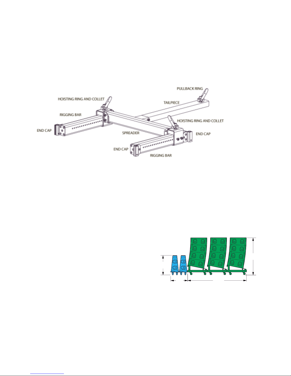
1.1 FLY-BAR PHYSICAL FEATURES
1.2 PALLETS
1.2.1 KF760 Pallet:
This pallet holds four KF760s tight-packed. This provides a flat top surface for a double deck truck pack.
The caster positions are adjustable to fit different truck ramp widths. Position the casters so they are the
same distances from the outside edges of the pallet.
The casters are secured to the pallet by a removable long connecting pin (see section 1.3). Remove the
pin and repositioning the casters as needed. Ensure that the connecting pins extend fully through the
holes and are fully locked.
The casters are replaceable allowing use of different
types of casters or wheel materials or wheel sizes as
needed for the particular conditions of use.
1.2.2 KF761 Pallet:
37"
This pallet holds one KF761 face down for transport
The caster positions are adjustable to fit different truck
ramp widths. Position the casters so they are the same distances from the outside edges of the pallet.
The casters are secured to the pallet by a removable long connecting pin (see section 1.3). Remove the
pin and repositioning the casters as needed. Ensure that the connecting pins extend fully through the
holes and are fully locked.
32"
112"
71"
The casters are replaceable allowing use of different types of casters or wheel materials or wheel sizes
as needed for the particular conditions of use.
KF760 Series Rigging Procedures PRELIMINARY DRAFT -- 21 Aug 01 Page 1 of 29
KF760 Series Rigging Procedures PRELIMINARY DRAFT -- 21 Aug 01
1.3 CONNECTING PINS
Two types of connecting pins are used with a KF760 array. The 1-1/4 inch or short connecting pins are
used for all enclosure to enclosure and enclosure to Fly-Bar connections. The 4 inch or long connecting
pins are used to connect Fly-Bar components together and secure the casters to the caster pallets. Both
types are single acting, double ball pins with a minimum double shear strength of 20,000 lb / 9,000 kg.
Shaft Diameter Length * Designation
3/8 in 4 in Short
3/8 in 1-1/4 in Long
* Measured from shoulder to the balls
CAUTION: Insert all enclosure connecting pins from the inside of the Hinge Tubes. Inserting the
connecting pins from the outside of the enclosure into the Hinge Tubes can and will result in
jammed pins. This is because the hole dimensions and clearances are not designed for inserting
the pins in this direction.
1.4 RIGGING PREPARATION
It is very important to properly prepare the Fly-Bar, enclosures, and Tail Bar or Pull-Back Bar for rigging.
If incorrectly configured beforehand, it will be more difficult and less efficient to rig an array and required
parts may get lost. In the following checklist, the locations of the connecting pins are where the pins
should normally be locked in for storage or transportation in anticipation of rigging an array. Following
this scenario, connecting pins will always be available where they are needed for the purposes listed.
The only exceptions are the two extra short connecting pins shipped with each enclosure used for locking
the hinges when the Pull-Back Bar is used. These are normally stored loose .
1.4.1 KF760 and KF761 Enclosures:
1. Leave a short connecting pin in the bottom hole of each Hinge Tube on each enclosure.
Use these to:
Attach an under hung KF760 or KF761 by engaging its four hinges.
Attach a KF760 on a pallet to the one below it by engaging its four hinges.
2. There are two additional connecting pins intended for locking the hinges provided with the KF760s and
KF761s. Do not store these in their rigging because the only places to put them will be in the way when
rigging. Store these pins loose where you will not lose them.
3. Do not leave connecting pins in any other holes other than as in #1.
1.4.2 Fly-Bar:
1. Leave a short connecting pin in the bottom hole of each Hinge Tube on the Fly-Bar. Use these to:
Attach the top KF760 or KF761 enclosure of the array to the Fly-Bar.
2. Leave four long connecting pins in each Hoisting Ring Collet. Note: these pins normally would be in
use if the Fly-Bar were left assembled. Use these to:
Attach the Hoisting Ring Collet to the Rigging Bars.
Attach the Hoisting Ring Collet to the Spreader.
1.4.3 Assembled Fly-Bar Left Connected to Top of a KF760 for Transportation and Storage
1. Lock the top enclosure s four hinges in their extended (up) position using the top hole in each Hinge
Tube and the bottom hole in each hinge. Use four short connecting pins for this. This will keep the hinges
from dropping into the Hinge Tube and thus keep the Fly-Bar from contacting the top enclosure.
KF760 Series Rigging Procedures PRELIMINARY DRAFT -- 21 Aug 01 Page 2 of 29

KF760 Series Rigging Procedures PRELIMINARY DRAFT -- 21 Aug 01
2. Secure the Fly-Bar to the top enclosure with four short connecting pins, one in each of the Fly-Bar s
four Hinge Tubes, attaching it through the hinges of the top enclosure.
1.4.4 Tail Bar:
Leave two long connecting pins in the Tail Bar for attaching it to the Spreader.
1.4.5 Pull-Back Bar:
No connecting pins stay with this part. If properly prepared for use (see section 1.4.1), there should be
two short connecting pins available in the bottom of any enclosure s Hinge Tubes for attaching the PullBack Bar to the bottom enclosure of the array.
1.5 TO PULL-BACK OR NOT TO PULL-BACK
The KF760 Wizard will show where the Spreader Bar must be positioned for the correct down tilt angle for
the entire array. If this angle is beyond what is possible by positioning the Spreader Bar, the Wizard will
indicated a pull-back is needed. This requires an additional pick point and chain motor.
1.5.1 Two pull-back methods:
1. Tail-Bar — This will pull the top rear of the array up to achieve the correct hang angle.
Advantages: The chain motors are all at essentially the same height. When running all three
motors, the lift distances will be about the same.
Disadvantages: The pull-back motor will have a much greater load on it than when using the Pull-
Back Bar. The number of degrees of pull-back is limited to ±15 degrees.
2. Pull-Back Bar — This will pull up on the bottom rear of the array to achieve the correct hang angle
Advantages: The pull-back motor will have a much less load on it than when using the Tail-piece.
The number of degrees of pull-back is not limited.
Disadvantage: The pull-back motor rides near the bottom of the array. When running all three
motors, the pull-back motor will lag behind in lift distance.
2 RIGGING PROCEDURES
The following rigging procedure is the recommended method for assembling and disassembling a KF760
array. While it is possible to use other techniques than the ones shown, EAW recommends you use the
procedures detailed below.
While these rigging procedures may seem complex, in reality they are quite easy to perform. During the
photography session for the pictures contained herein, the array depicted in the procedures was loaded in
and loaded out several times. Each time, the complete load-in or load-out procedure took approximately
six minutes as performed by two, non-professional personnel.
The rigging sequences show the steps for load in and load out of an eight over two array. This means
eight KF760s are under hung with two KF761s. Depending on the number and types of enclosures in a
KF760 array, the sequence you need may differ. However, the specific details of the steps for rigging
KF760s or KF761s will be the same.
WARNING: During the rigging procedure, there will be considerable weight being moved and lifted
overhead. Depending on the array configuration, the array may tend to swing forward or
backwards as additional enclosures are added and as the array s weight is taken by the chain
motors. Personnel near the array must be aware that this can and will happen and should
position themselves appropriately to prevent injury or death.
KF760 Series Rigging Procedures PRELIMINARY DRAFT -- 21 Aug 01 Page 3 of 29

KF760 Series Rigging Procedures PRELIMINARY DRAFT -- 21 Aug 01
WARNING: The array should always be level side-to-side. This should be monitored and adjusted
as needed throughout the rigging procedure to prevent the array from swinging sideways as the
array s weight is being taken by the chain motors. Personnel near the array must be aware that
this can and will happen and should position themselves appropriately to prevent injury or death.
CAUTION: During the following procedures, insert all short connecting pins from the inside of the
Hinge Tubes. Inserting the pins from the outside of the enclosure into the Hinge Tubes can and
will result in jammed pins. This is because the hole dimensions and clearances are not designed
for inserting the pins in this direction.
IMPORTANT NOTE: With the exception of connecting pins used to lock the hinges, connecting pins
should be inserted into one of the bottom holes of each enclosure s four hinge tubes. This is true whether
the enclosure has anything attached beneath it (another enclosure or a pallet) or not. Failure to follow
this rule will result in either lost connecting pins or connecting pins not available when and where they are
needed during load-in and load out procedures.
IMPORTANT NOTE FOR SPLAYED ENCLOSURES: Two of the six short connecting pins supplied with
each KF760 and KF761 are intended as hinge locking pins when the rear of the enclosures are splayed
and the Pull-Back Bar is used. Normally gravity keeps the rears of splayed enclosures apart, thus
maintaining the splay. When a Pull-Back Bar is used, it creates an upward force on the rear of the
enclosures, tending to push the rears of splayed enclosures together, thus collapsing the splay.
The solution is to lock the hinge in the top of the bottom enclosure between any two splayed enclosures.
To do this, insert a connecting pin into the top hole of the each rear Hinge Tube and through the bottom
of the hinge. This prevents the hinge from moving back down into its own Hinge Tube when an upward
force is applied to the rear of the enclosure. When enclosures are tight-packed using the Pull-Back bar,
the hinge locking pin is not needed.
2.1 PICK POINTS
Establish and rig the two pick points for the array with chain motors rated for the load.
If a pull back is used, establish and rig three pick points with chain motors rated for the load.
2.2 FLY-BAR ASSEMBLY
1. The Fly-Bar is assembled by attaching the Spreader to the Rigging Bars. Use two long connecting
pins at each end of the Spreader to attach it to the Hoisting Ring collets. If the pull-back Tail Bar is to be
used, insert the Tail Bar arm into the sleeve in the center of the Spreader and secure with two long
connecting pins.
2. The front-to-back Spreader position is determined by using the KF760 Wizard software. Position the
Spreader Bar as indicated by the Wizard.
3. Attach the Fly-bar to the chain motors using the two hoisting rings on the Rigging Bar.
Ensure the Hoisting Ring Collets are attached to the Rigging Bar with two long connecting pins each.
Ensure the Spreader is attached to the Hoisting Ring Collets with two long connecting pins at each end.
2.3 LOAD IN
2.3.1 First KF760 Pallet
KF760 Series Rigging Procedures PRELIMINARY DRAFT -- 21 Aug 01 Page 4 of 29
KF760 Series Rigging Procedures PRELIMINARY DRAFT -- 21 Aug 01
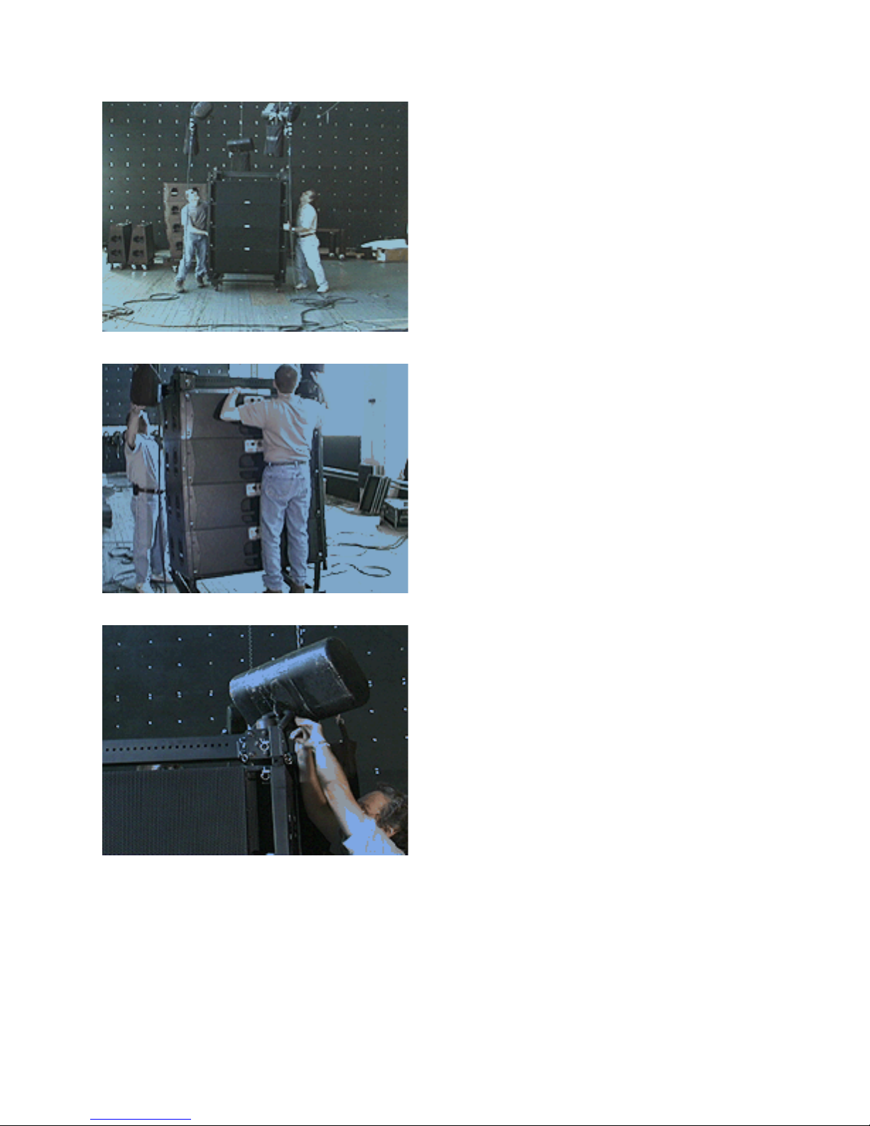
1. Bring in the first pallet of four KF760s and position it under the chain motors.
2. Lower the chain motors for attachment ot the Fly-Bar Hoist Rings.
3. If the Fly-Bar was transported attached to palleted KF760s then attach the chain motors to the Fly-Bar
and skip the next steps.
4. If the Fly-Bar was transported un-attached from a KF760 pallet then attach the chain motors to the
assembled Fly-Bar and perform the next two steps (not shown):
1. Land the Fly-Bar on top enclosures so the weight is off the chain motors.
KF760 Series Rigging Procedures PRELIMINARY DRAFT -- 21 Aug 01 Page 5 of 29
KF760 Series Rigging Procedures PRELIMINARY DRAFT -- 21 Aug 01
2. Push up each of four hinges on top enclosure into fly-bar Hinge Tubes and pin to the Fly-Bar
Hinge Tube with the short connecting pins. Ensure that pins extend fully through the hinges and
Hinge Tubes and are fully locked.
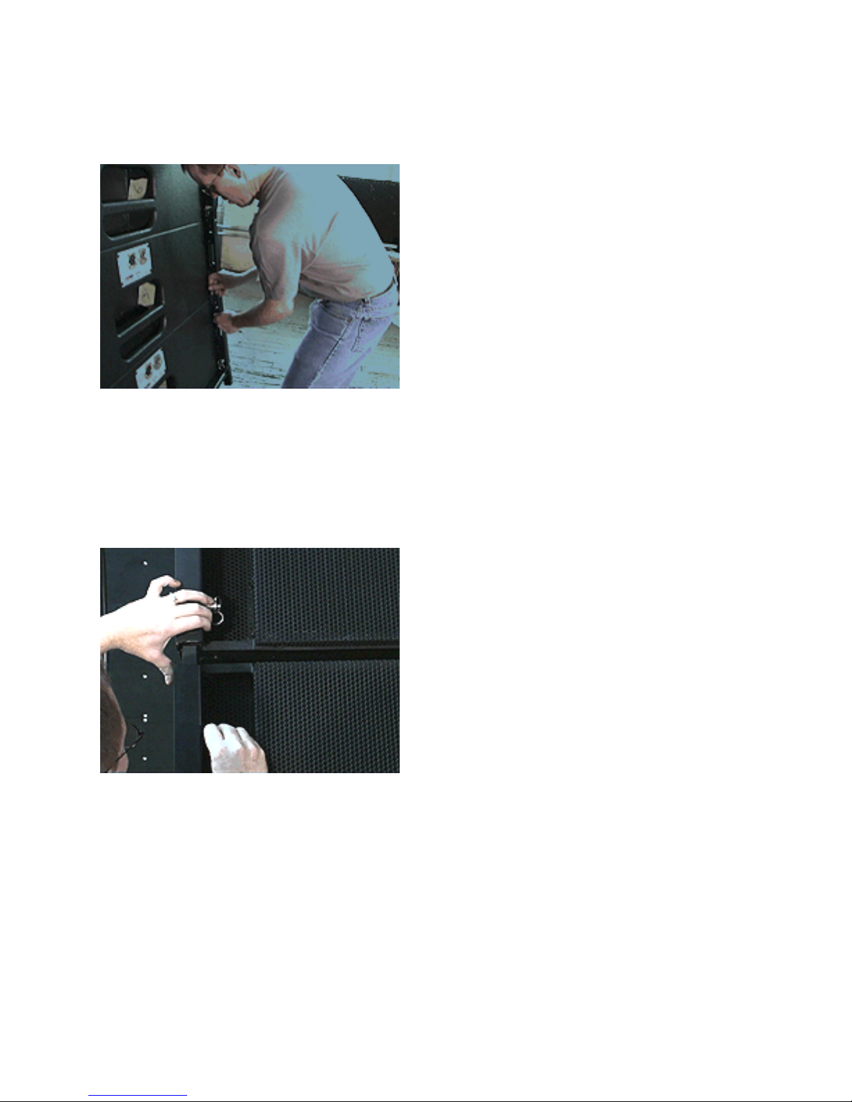
5. Adjust the rear hinges between each two enclosures for the desired rear splay angle by positioning
each of the two hinges into the Hinge Tubes of the enclosure above. Use the short connecting pin to
engage the hinge using the appropriate one of the three holes provided in the each upper enclosure
Hinge Tube.
Top hole = tight packed
Center Hole = 1-1/2¡ splay
Bottom hole = 3¡ splay
Ensure that the connecting pins extend fully through the hinges and Hinge Tubes and are fully locked.
5. Ensure that all hinges on the front of the enclosures are positioned and pinned so that enclosure fronts
will be tight-packed when flown.
6. Pull-Back Bar (not shown):
If the Pull-Back Bar is to be used, the rear hinges on any splayed enclosures must be locked in position to
prevent the hinges from moving down into their own Hinge Tubes when the pull-back force is applied. To
lock the hinges, insert a connecting pin into the top hole of the each rear Hinge Tube and through the
bottom of the hinge. This prevents the hinge from moving back down into its own Hinge Tube when an
upward force is applied to the rear of the enclosure. When enclosures are tight-packed, the hinge locking
pin is not needed.
KF760 Series Rigging Procedures PRELIMINARY DRAFT -- 21 Aug 01 Page 6 of 29
KF760 Series Rigging Procedures PRELIMINARY DRAFT -- 21 Aug 01
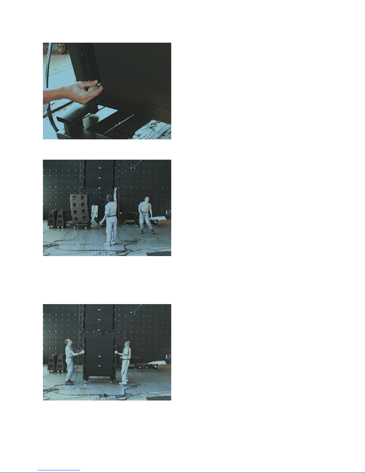
7. Disconnect pallet from the bottom enclosure by removing the four short connecting pins. Insert the
four connecting pins in the bottom enclosure Hinge Tubes.
8. Fly the first four enclosures to an appropriate working height for the next step and push the KF760
pallet aside. Later this will be used as a KF761 rigging aid.
NOTE: When array is flown, the rear enclosure splays will automatically open up to the desired angle.
2.3.2 Second And Subsequent KF760 Pallets
1. Bring in the second pallet of KF760s and position it under the flown array.
KF760 Series Rigging Procedures PRELIMINARY DRAFT -- 21 Aug 01 Page 7 of 29
KF760 Series Rigging Procedures PRELIMINARY DRAFT -- 21 Aug 01
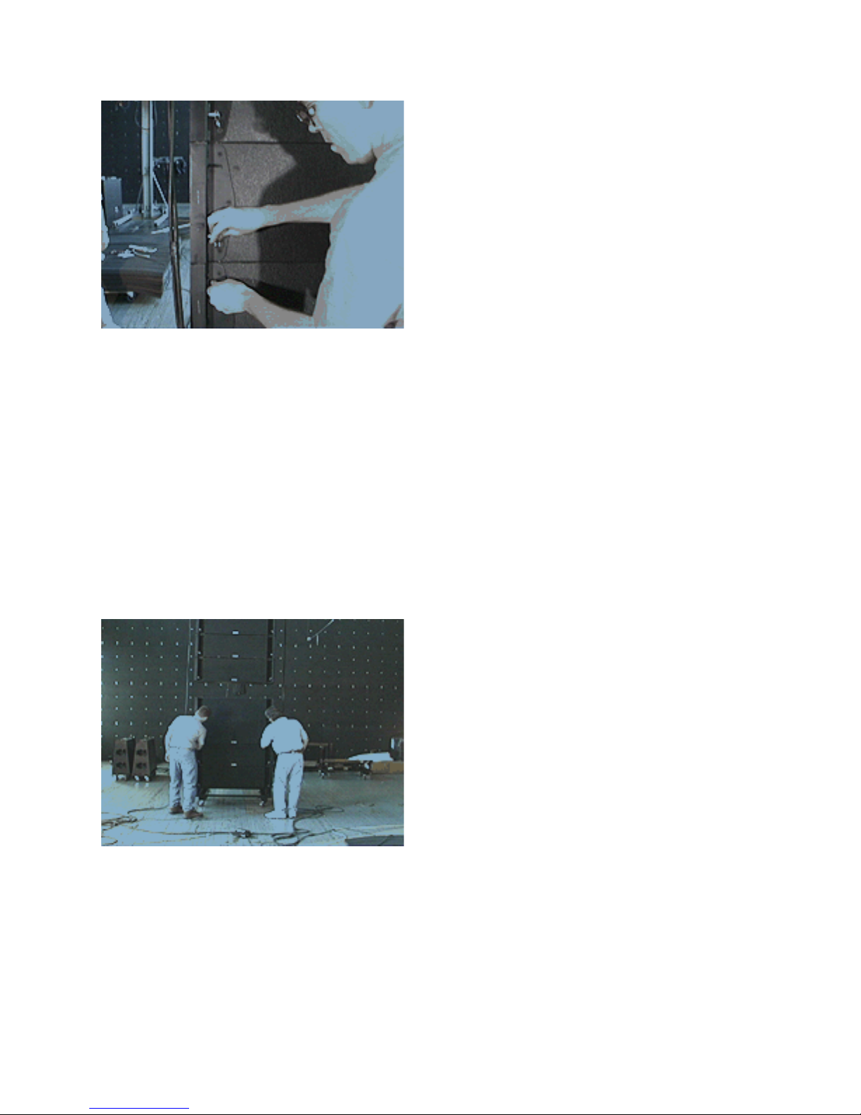
2. Adjust the rear hinges between each enclosure for the desired rear splay angle by sliding the each of
the four hinges into the Hinge Tubes of the upper enclosure. Use the short connecting pin to engage the
hinge using the appropriate one of the three holes provided in the each upper enclosure Hinge Tube.
Top hole = tight packed
Center Hole = 1-1/2¡ splay
Bottom hole = 3¡ splay
Ensure that pins extend fully through the hinges and Hinge Tubes and are fully locked.
3. If Using the Pull-Back Bar (not shown):
If the Pull-Back Bar is to be used, the rear hinges on any splayed enclosures must be locked in position to
prevent the hinges from moving down into their own Hinge Tubes when the pull-back force is applied.
To lock the hinges, insert a connecting pin into the top hole of the each rear Hinge Tube and through the
bottom of the hinge. This prevents the hinge from moving back down into its own Hinge Tube when an
upward force is applied to the rear of the enclosure. When enclosures are tight-packed, the hinge locking
pin is not needed.
4. Ensure that all hinges on the front of the enclosures are positioned and locked so that enclosure fronts
will be tight-packed when flown.
KF760 Series Rigging Procedures PRELIMINARY DRAFT -- 21 Aug 01 Page 8 of 29

KF760 Series Rigging Procedures PRELIMINARY DRAFT -- 21 Aug 01
5. Disconnect pallet from the front of the bottom enclosure by removing the four short connecting pins.
Insert the four connecting pins in the bottom enclosure Hinge Tubes.
6. Bring in flown enclosures to within about 1in / 25 cm of the front top of palleted enclosures.
7. Slide up the two front hinges of the topmost palleted enclosure into bottommost flown enclosure and
temporarily pin the hinge to the topmost palleted enclosure s Hinge Tubes.
NOTE: This aligns the KF760 with the flown enclosure above it for the next step.
KF760 Series Rigging Procedures PRELIMINARY DRAFT -- 21 Aug 01 Page 9 of 29
 Loading...