

EAW KF755F User Manual
SPECIFICATIONS KF755F
DESCRIPTION
PERFORMANCE
APPLICATION
One Main Street, Whitinsville, MA 01588 508 234 6158 Toll Free 800 992 5013 FAX 508 234 8251 info@eaw.com www.eaw.com
EAW products are continually improved. All specifications are therefore subject to change without notice. KF755F/2 pp October 2001 Printed in USA
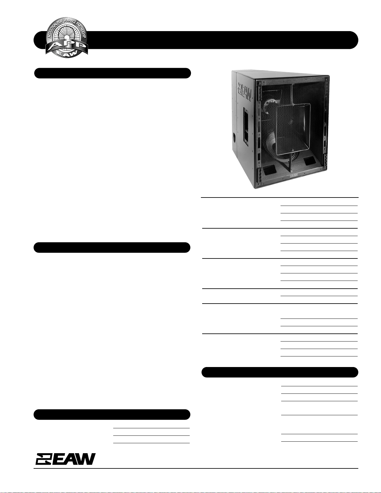
The KF755F 3-way tri-amplified full ran g e system is the d ownfill companion to the KF750F array module.
Since the larg e mid frequen cy horn con tains both the hi gh
and
low frequency subsystems, the overall package is just 31-in
high. Still, the KF755F provides consistent wideband pattern
control in both the vertical and horizontal planes.
The large MF horn loads a specially designed 10-in midrange
cone whose geometry exactly matches the rear of its phase
plug assembly. By developing the driver and phase plug as a
single unit, pathlength discontinuities within the MF passband have been eliminated without compromising the directional qualities of the source as all previous phase plug
designs have.
The 2-in exit/4-in voice coil HF compression driver is mounted
on an asymmetrical 35° x 35° constant directivity horn
mounted coaxially within the MF horn flare. Vertical coverage
is 0° to -35°.
The KF755F’s 15°-per-side trapezoidal enclosure features
eight 4-position flytracks (four each front and rear) that
accept industry-standard flyclips.
The KF755F provid es optimized d ownfill coverage below flown
arrays or, when inverted, provides upfill balcony coverage
from ground-stacked arrays when flying arrays are either not
allowed or not desired.
At just 31-in tall and under 200 pounds per module, KF700
Series arrays are sm aller, ligh ter, mor e effici ent an d, th er efor e ,
more powerful than those built with other systems. These
smaller , li ghter arr ays ar e easier to fly, r equire less tru ck space
and permit more open sight lines to cover any given venue.
The KF750F works with a companion downfill module, the
KF755F to provide full range nearfield coverage below the
array. The KF755F’s smooth power response produces remarkably even SPL levels throughout the coverage area, allowing
it to be used as a stand-alone system when necessary in
applications demanding that coverage pattern.
Applications include:
Concert Tours Performing Arts Centers
Houses or Worship Theaters
Axial Sensitivity (dB SPL, 1 Watt @ 1m)
LF 99
MF 108
HF 115
Impedance (Ohms)
LF 8
MF 8
HF 8
Power Handling, (Watts Continuous)
LF 600
MF 400
HF 200
Recommended High-Pass Filter
24 dB/Octave 30 Hz
Calculated Maximum Output (dB SPL @ 1m)
LF Peak/Long Term 132/126
MF Peak/Long Term 140/134
HF Peak/Long Term 144/138
Nominal Coverage Angles, -6 dB points (degrees)
Horizontal 35
Vertical 35 (0 to -35)
PHYSICAL
Configuration 3-way, full range
Powering Tri-amplified
LF Subsystem 12-in cone, vented
MF Subsystem 10-in cone, Radial Phase Plug™
asymmetrically horn-loaded
HF Subsystem 2-in Exit/4-in voice coil
compression driver on
asymmetrical high Q horn
Coverage Angles 35° (h) x 35° (v, 0° to -35°)
Frequency Response (Hz)
±3 dB 48 Hz to 18 kHz
-10 dB 30 Hz
SPECIFICATIONS KF755F
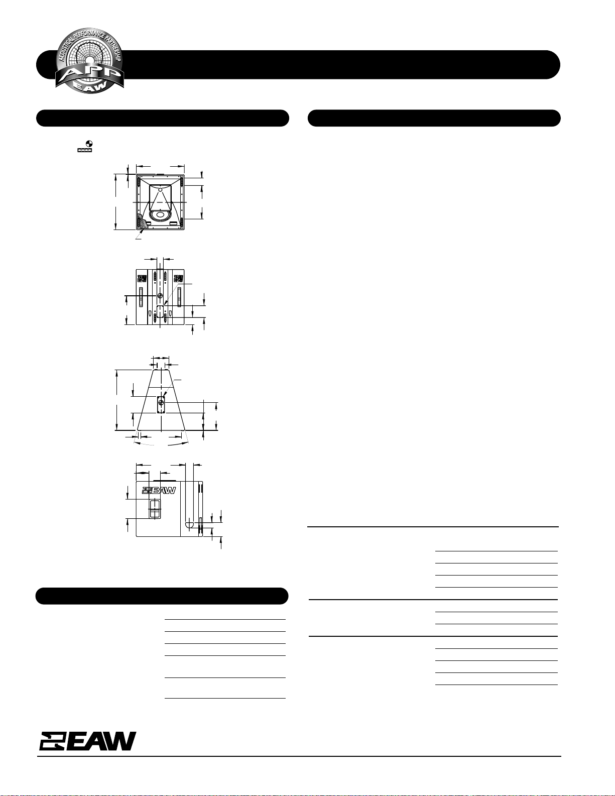
DIMENSIONAL DRAWING
A & E SPECIFICATIONS
One Main Street, Whitinsville, MA 01588 508 234 6158 Toll Free 800 992 5013 FAX 508 234 8251 info@eaw.com www.eaw.com
EAW products are continually improved. All specifications are therefore subject to change without notice. KF755F/2 pp October 2001 Printed in USA
Cabinet Type (shape) Trapezoid
Enclosure Materials Baltic birch plywood
Finish Black catalyzed polyurethane
Connectors 2x Neutrik NL8 Speakon
Suspension Hardware 8x 4-position flytracks
(4 each front and rear)
Grille Powder coated perforated steel,
foam backed
Dimensions inches millimeters
Height 31.4 797
Width (Front) 27.0 686
Width (Rear) 8.8 233
Depth 34.0 864
Trapezoid Angle 15 degrees per side
Weights pounds kilograms
Net Weight 168 76.4
Shipping Weight 178 81.0
Companion Systems
Sub Bass SB750F/SB1000e/KF940
Full Range KF750F
Accessories KF700 Series caster pallet
The three-way full range downfill loudspeaker system shall
incorporate a 12-in LF transducer, a 10-in MF cone transducer and a 2-in exit/4-in voice coil compr ession d river HF tran sducer.
The LF driver shall be mounted in a vented enclosure tuned
for optimum low frequency response. The MF driver shall be
mounted on an asymmetrical, large-format horn and shall be
coupled to a phase plug whose geometry exactly matches
that of the driver. The HF driver shall be loaded on an asymmetrical constant directivity horn with a nominal coverage
pattern of 35° (h) x 35° (v, 0° to -35°).
System frequency response shall vary no more than ±3 dB
from 48 Hz to 18 kHz measured on axis. The loudspeaker’s
subsystems (LF/MF/HF) shall produce a Sound Pressure Level
(SPL) of 103/109/115 dB SPL on axis at 1 meter with a power
input of 1 Watt, and shall be capable of producing a peak
output of 132/140/144 dB SPL on axis at 1 meter. The subsystems (LF/MF/HF) shall handle 600/400/200 Watts of
amplifier power (continuous) and shall have nominal impedances of 8/8/8 Ohms.
The loudspeaker enclosure shall be trapezoidal in shape. It
shall be constructed of multi-ply void-free cross-grain-laminated Baltic birch plywood and shall employ extensive internal bracing. It shall be finished in black catalyzed
polyurethane. Input connectors shall be 2x Neutrik NL8
Speakon. A total of eight 4-position flytracks (4 each front
and rear) shall be provi ded . Th e fron t o f the lou dspeak er shall
be covered with a powder coated perforated steel grille.
The three-way full ran g e d ownfill lou dspeak er system shall be
the EAW model KF755F.
CABINET TO BE SYMMETRICAL ABOUT CENTERLINE DESIGNATIONS.
INDICATES CENTER OF BALANCE.
INDICATES FLY TRACK MOUNTING POINTS.
FRONT
18.88
L
C
27.00
GRILL PARTIALLY SHOWN
4.13
31.38
.38
TOP/BOTTOM
1
7
4.44
(.25)
STACK PAD
L
C
22.90(1.37)
(8.78)
9.25
34.00
9.81
15.62
30°
SIDES
3.00
7.75
4.50
6.44
27.80
BACK
INPUT
L
C
6.63
4.00
16.25
3.63
510776 (0)
7/26/99
Manufacturing tolerances are +/- 0.13 and +/- 1°
PHYSICAL continued
 Loading...