

EAW KF755 Series, SB750 Series, KF750 Series Owner's Manual
KF700 SERIES
OWNER’S MANUAL
KF750 | KF755 | SB750


i
KF700 Series Owner’s Manual
TABLE OF CONTENTS
Section 1 Read This First.................................................................................................................................................ii
1.1 Safety Precautions ..............................................................................................................................ii
1.2 General Precautions...........................................................................................................................ii
1.3 Important Information for Professional Riggers ......................................................................ii
Section 2 Unpacking .......................................................................................................................................................iii
2.1 Shipping Damage..............................................................................................................................iii
2.2 Returning Products to EAW ............................................................................................................iii
Section 3 Quick Start .......................................................................................................................................................iv
3.1 Important Safety and Rigging Information ..............................................................................iv
3.2 Audio Signal Connections ..............................................................................................................iv
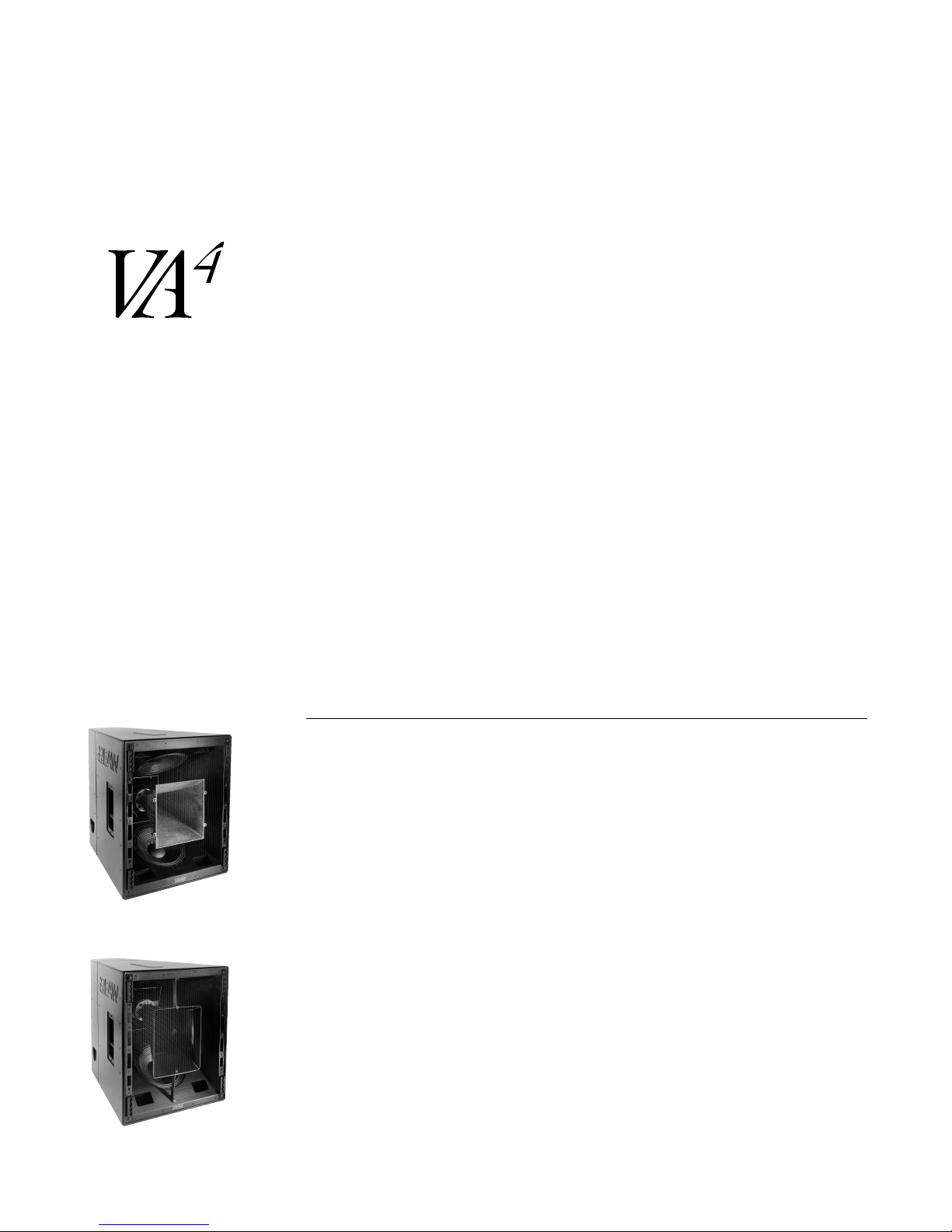
Section 4 Description ......................................................................................................................................................1
4.1 Overview................................................................................................................................................1
Section 5 Operation..........................................................................................................................................................2
5.1 KF700 Series Products.......................................................................................................................2
5.2 Input Connections..............................................................................................................................3
5.3 Mechanical Characteristics and Accessories .............................................................................3
5.4 Electrical Characteristics and Accessories..................................................................................5
5.5 Array Design .........................................................................................................................................6
5.6 System Truck-Pack..............................................................................................................................7
Section 6 Maintenance and Service ......................................................................................................................8
6.1 Warranty ................................................................................................................................................8
6.2 How to Contact EAW..........................................................................................................................8
6.3 System Maintenance and Repair Tips..........................................................................................9
6.3.1 KF750F..................................................................................................................................9
6.3.2 KF750P...............................................................................................................................12
6.3.3 KF750P-WP.......................................................................................................................14
6.3.4 KF755F...............................................................................................................................16
6.3.5 KF755P...............................................................................................................................19
6.3.6 KF755P-WP.......................................................................................................................21
6.3.7 SB750F...............................................................................................................................22
6.3.8 SB750P...............................................................................................................................23
6.3.9 SB750P-WP.......................................................................................................................24
Section 7 Specifications ..............................................................................................................................................25
Congratulations on purchasing the latest sound reinforcement innovation from Eastern Acoustic Works. The KF700
Series is built upon the same fundamental design principles that EAW has upheld since the introduction of the
KF850 Series of loudspeakers in the 1980’s. This new product line draws elements from Virtual Array Technology™
and PhasedPoint Source Technology™, combining these with new patented advances in transducer design and system
integration. The KF700 Series centers on a design approach that optimizes building arrays in the three dimensions of
physical space while also addressing the key acoustical issues that reside in the fourth dimension of time.

ii
Section 1 Read this first
The terms “Caution,” “Warning” and “Danger” are used throughout this manual to alert
the reader to important safety considerations. If you have any questions about any
aspects of these cautions, contact your local dealer, distributor or EAW.
CAUTION: describes an operating condition or user action that may expose the equipment
or user to potential damage or danger.
WARNING: describes an operating condition or user action that will cause damage to the
equipment or injure the user.
DANGER: describes an operating condition or user action that will immediately damage
the equipment or be extremely dangerous or possibly life-threatening to the user.
1.1 Safety Precautions
Rigging (flying) must be performed only by a professional rigger. See Section 1.3 for
information for professional riggers.
1.2 General Precautions
WARNING: Some aspects of rigging and other related fields for which EAW manufactures,
sells or distributes equipment are potentially hazardous. Any person using this equipment
is personally responsible for his own safety. EAW transactions are made with the assumption
that the purchaser is a qualified individual or will have only qualified individuals perform
work with the equipment. EAW will not be liable for any damages arising from the use of
equipment sold to purchaser.
1.3 Important Information about Rigging
Prior to suspending any EAW loudspeaker enclosures overhead, it is essential that the
user
be familiar with the load ratings, rigging techniques and special safety considera
tions
appropriate to suspending loudspeakers overhead. The user must determine the load
requirements, dynamic loading and any other contributing factors affecting the flown
loudspeakers. The user must determine the proper safety factor for specific applications
and the required load rating of the connection points. EAW strongly recommends that all
rigging be done in accordance with and in compliance with all federal, state and local
regulations, relative to properly securing suspended loads prior to usage. The user
assumes liability for proper design, installation and use of rigging systems.
EAW strongly recommends the following rigging system practices:
1.
Documentation: Thoroughly document the rigging design with detailed drawings
and parts lists.
2.
Analysis: Have a licensed structural engineer, registered architect or other qualified
professional review and approve the rigging design before its implementation.
3. Installation: Have a qualified professional rigger install and inspect the rigging
system.

iii
DANGER: Loudspeakers should be suspended overhead only by persons with a knowledge of the proper hardware and rigging techniques. When stacking or pole-mounting
loudspeakers, be sure they are stabilized and secured from falling over or being accidentally
pushed over. Failure to follow these precautions may result in damage to the equipment,
personal injury, or death.
EAW strongly recommends the following rigging system practices:
1. DOCUMENTATION:
Thoroughly document the rigging system design with
drawings and detailed parts lists.
2. PROFESSIONAL REVIEW:
Have a licensed structural engineer, registered
architect or other qualified professional review and officially approve the
rigging design before its implementation.
3. PROFESSIONAL INSTALLATION:
Have the rigging system installed and
inspected by a qualified professional rigger.
Section 2 Unpacking
2.1 Shipping Damage
You should have already visually inspected the outside of the shipping carton and noted
any damage on the shipping bill you signed. After unpacking, if you find concealed damage
to the loudspeaker, save the packing materials for the carrier’s inspection, notify the carrier
immediately and file a shipping damage claim.
Although EAW will help in any way possible,
it is always the responsibility of the receiving
party to file any shipping damage claim.
The carrier will help prepare and file this claim.
2.2 Returning Products to EAW
If this loudspeaker must be returned to EAW, contact EAW for a Return Authorization. Use
the original shipping carton and packing materials. If the shipping carton is damaged,
contact EAW for a new carton. EAW will not be responsible for damage caused by
inadequate packing.

iv
Section 3 Quick Start
NOTE: This section is intended only for qualified professional installers.
3.1 Important Safety and Rigging Information
CAUTION: Read all of Section 1, "Read This First", for important general, safety and
rigging precautions.
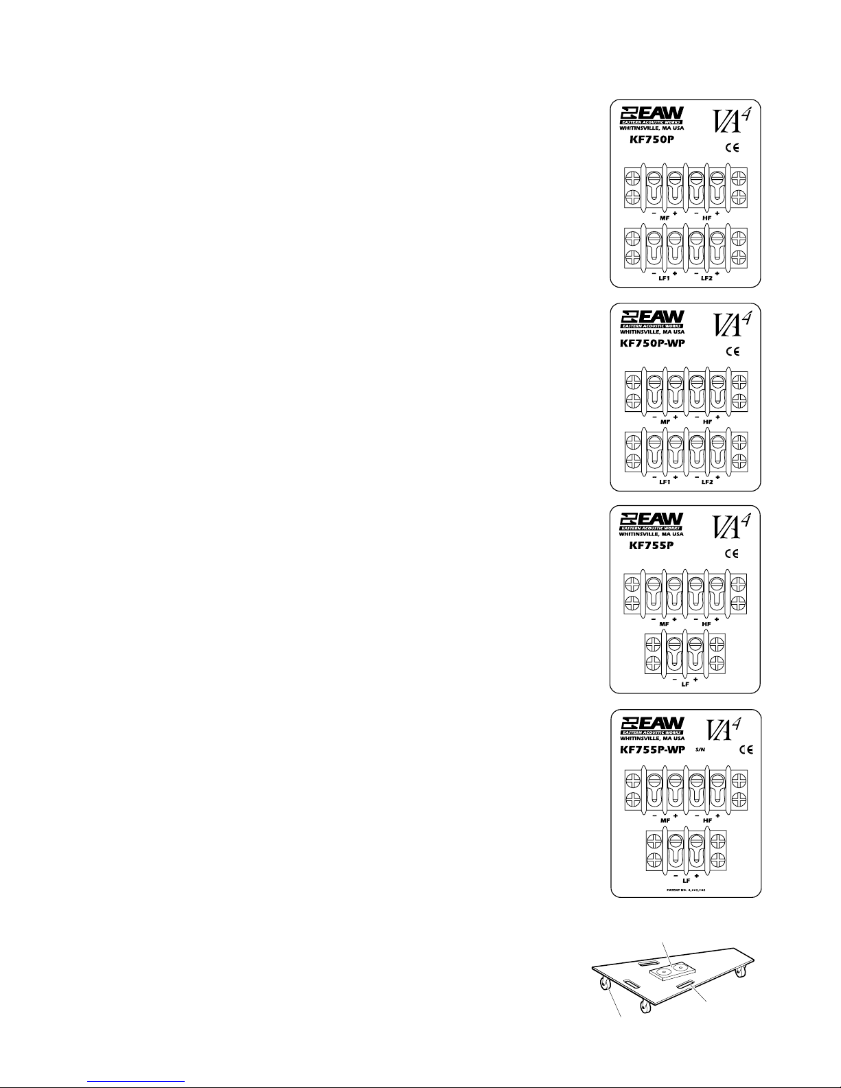
3.2 Audio Signal Connections
The audio signal connections are via Neutrik NL8 connectors or barrier strips. The two
NL8s are wired in parallel.
KF750F - 2 x NL8
LF1: pins 1 (+/-)
LF2: pins 2 (+/-)
MF: pins 3 (+/-)
HF: pins 4 (+/-)
KF750P and KF750P-WP - 2 x 4-terminal Barrier Strips
LF1: bottom strip terminals 1 (-) and 2 (+)
LF2: bottom strip terminals 3 (-) and 4 (+)
MF: top strip terminals 1 (-) and 2 (+)
HF: top strip terminals 3 (-) and 4 (+)
KF755F - 2 x NL8
Pins 1 (+/-) not used
LF: pins 2 (+/-)
MF: pins 3 (+/-)
HF: pins 4 (+/-)
KF755P and KF755P-WP - 1 x 2-terminal + 1 x 4-terminal Barrier Strips:
LF: bottom strip terminals 1 (-) and 2 (+)
MF: top strip terminals 1 (-) and 2 (+)
HF top strip terminals 3 (-) and 4 (+)
SB750 - 2 x NL8
Left driver*: pins 1 (+/1)
Right driver*: pins 2 (+/-)
Not used: pins 3 (+/-)
Not used: pins 4 (+/-)
*Note: Driver position is looking from front.

1
Section 4 Description
4.1 Overview
Professional loudspeaker systems are designed to optimize spectral, spatial, temporal and
usability performance attributes. Quite often optimization in one area compromises
performance in another. Thus, loudspeaker design is the art of balancing these goals while
minimizing compromise. In order to achieve these goals for the KF700 Series, key developments allowed for performance enhancement in each area without compromise in others.
4.1.1 SPECTRAL
The KF700 Series are true three-way designs. The goal was to develop
systems with greater
low frequency extension and greater overall mid frequency bandwidth. Traditionally these
goals required increased physical size. This was not an option. The
KF700 Series loudspeak-
ers were designed as uni-axial enclosures in which all the transducers
(woofer, mid-range,
and high frequency) share a common acoustic axis. This
permitted using larger horns for a
more consistent coverage pattern over a wider frequency
range and provided more available
enclosure volume for deeper bass response while
actually reducing physical size. A new,
patented mid frequency phase plug was also
developed that allows for improved upper
mid frequency response from a cone transducer
through a large format horn.
4.1.2 SPATIAL
The KF700 Series have 35° x 35° coverage patterns. This enhances building arrays and
increases overall system output capability. Conventional phase plugs create beam-width
narrowing in the upper portion of the mid-range. The patented KF700 Series mid
frequency phase plug provides upper mid-range extension without creating this narrowing.
The uni-axial approach minimizes the impact of “apparent apex error”. This occurs when
the separation between physically misaligned transducers changes as the listening point
changes. The KF750 horn designs draw heavily from the SimplePhase™ horns used in the
KF900 Series in order to achieve more seamless coverage between arrayed enclosures.
The low frequency section uses multiple woofers in a dipole configuration to reduce off
axis low frequency energy and thus increase directivity. Research showed that the directivity
of the low frequency section could be smoothly matched to that of the mid frequency section.
This is done by optimizing the ratio between the woofer spacing within the mid frequency
horn and the dimensions of the mid frequency horn mouth. This configuration with its
dimensional ratio is patented.
4.1.3 TEMPORAL
The temporal focus is once again on the mid-range section. A mid frequency cone transducer tends to provide better tonality and lower distortion than standard compression
drivers, but can smear events in the time domain. This was resolved through a redesign of
the mid-range transducer geometry. The multi-axis approach and its subsequent impact
on apparent apex error also serves to minimize temporal inconsistencies from transducer
to transducer within the enclosure.
4.1.4 USABILITY
Usability goals were satisfied by making the enclosures small. The uni-axial approach
met all the performance goals while allowing for a reduction in overall package size. For
the most consistent coverage pattern through the low to mid frequency crossover region,
the optimal spacing of woofers is smaller than the optimal height of the mid frequency
horn. This allows the woofers to reside within the mid frequency horn, once again
resulting in a small overall package size.
In order to provide simple rigging, the standard KF850 flytrack was chosen. The KF750
utilizes these tracks on the front and back of the enclosure, eliminating the need for putting
fingers between cabinets during array assembly or disassembly. Finally, some internal
parts have been molded of lightweight materials in order to meet the desired enclosure
weight of less than 200 pounds.
4.1.5 VA4DEFINED
The system overview illustrates that the KF700 Series development was driven by enhancing
the acoustical performance of the loudspeaker systems as it relates to its arrayability. Each
loudspeaker must therefore array effectively both horizontally and vertically. Consistent
controlled coverage patterns in three dimensions guarantees predictable array results
from venue to venue.
The development goals also dictated that the KF700 Series improve upon the time
domain behavior, particularly in the vocal region. The ability of a loudspeaker to main
tain
the temporal integrity of the original input signal is easily as important as the frequency
response in determining the quality of the sound reproduction. Therefore, if harmonics
lead or lag fundamentals in the reproduction, then the original signal, and perhaps even
the intent of the performer, will be distorted. The ability to maintain the input signal’s
temporal integrity while delivering smooth frequency response to a well-defined coverage
area is ultimately the goal of any loudspeaker.
Consistently achieving the desired coverage from a loudspeaker array for a given venue
is governed by performance in the three dimensions of space. Maintaining temporal
coherence is governed by the fourth dimension of time. Meeting all of these criteria truly
addresses system performance in four dimensions. This four-dimensional design
approach is VA
4
technology.
4.1.6
WEATHER-PROTECTED (WP MODELS)
The KF700P-WP and SB750P-WP models are weather-protected for permanent
install
ations. The exterior of the enclosure is laminated with a water-resistant fiberglass
coating. A 2-layer grille is used to prevent water from entering the front of the enclosure.
The outside layer is powder-coated perforated steel for physical protection. The rear layer
is a 1/8 inch thick foam to break up driven water droplets. Behind the grille assembly, a
layer of 100 x 100 wires per inch stainless steel mesh is affixed to the enclosure to prevent
any water spray from entering the front of the enclosure. The input panel and back
doghouse are weather-sealed with rubber strips to prevent water intrusion.
Section 5 Operation
5.1 KF700 Series Products
5.1.1 KF700 MODELS
Model Name Description Primary Application
KF750F Three-way Concert touring
KF750P Three-way Permanent installation
KF750P-WP Three-way Outdoor installation
KF755F Three-way Concert touring downfill
KF755P Three-way Permanent installation downfill
KF755P-WP Three-way Outdoor installation downfill
SB750F Dual 18-in. Concert touring subwoofer
5.1.2 KF700 SERIES PRODUCT WEIGHTS
System Net (lb / kg) Shipping (lb / kg)
KF750F 198 / 90.0 230 / 104.6
KF750P 187 / 85.0 201 / 91.4
KF750P-WP 205 / 93.2 221 / 100.5
KF755F 198 / 90.0 232 / 105.5
KF755P 180 / 81.8 203 / 92.3
KF755P-WP 205 / 93.2 223 / 101.4
SB750F 193 / 87.7 202 / 91.8
KF750
KF755
2
3
5.1.3
EQUIPMENT SUPPLIED
Each model is shipped individually boxed, two of which fit on one shipping pallet.
Concert touring versions include four cable links, which comprise two fly clips and a
load-rated cable whose length is optimized for creating flown arrays.
5.1.4
ARRAYS
Flying one row of downfill is recommended when more than one row of KF750 loudspeakers is flown. At least one SB750F subwoofer is recommended for every two KF750s
or KF755s.
For more information on building arrays, please refer to the KF700 Touring Usage Guide
available at ftp://ftp.eaw.com/ProductGuides/KF700TouringUsageGuide.pdf. Most of
the basic array building concepts described in the Touring Usage Guide apply equally to
permanent installations.
5.2 Input ConnectIons
KF750F - 2 x NL8
LF1: pins 1 (+/-)
LF2: pins 2 (+/-)
MF: pins 3 (+/-)
HF: pins 4 (+/-)
KF750P and KF750P-WP - 2 x 4-terminal Barrier Strips
LF1: bottom strip terminals 1 (-) and 2 (+)
LF2: bottom strip terminals 3 (-) and 4 (+)
MF: top strip terminals 1 (-) and 2 (+)
HF: top strip terminals 3 (-) and 4 (+)
KF755F - 2 x NL8
Pins 1 (+/-) not used
LF: pins 2 (+/-)
MF: pins 3 (+/-)
HF: pins 4 (+/-)
KF755P and KF755P-WP - 1 x 2-terminal + 1 x 4-terminal Barrier Strips:
LF: bottom strip terminals 1 (-) and 2 (+)
MF: top strip terminals 1 (-) and 2 (+)
HF top strip terminals 3 (-) and 4 (+)
SB750 - 2 x NL8
Left driver*: pins 1 (+/1)
Right driver*: pins 2 (+/-)
Not used: pins 3 (+/-)
Not used: pins 4 (+/-)
*Note: Driver position is looking from front.
Note: All models can be special ordered with AP or EP 4, 6 and 8-conductor connectors.
5.3 Mechanical Characteristics and Accessories
5.3.1 CASTER PALL E T S
The KF700 Series includes an optional rugged caster pallet (EAW P/N 255049) designed
for years of reliable service in concert touring applications. Caster pallets can be
ordered separately in quantities suitable to particular truck packing strategies.
CENTRAL RAISED PLATFORM WITH TWO MAGNETS
THREE HANDLES
FOUR WHEEL CASTERS
4
KF700 Series caster pallets are constructed of 15 mm Baltic birch plywood with four
mounted wheel-casters. The caster pallet shares a common footprint with KF700F
enclosures. The pallet incorporates a central raised platform that keys into a recess on the
bottom of any enclosure. Magnets on the platform register to steel plates in the recess,
attaching the pallet to the enclosure. The caster pallet has three handles for easy transport
when not connected to a KF700 Series enclosure.
5.3.2 GROUND STACKING
All KF700(F) Series enclosures are equipped with a UHMW (Ultra High Molecular
Weight) plastic stacking pad that keys into the recess in the bottom of another enclosure
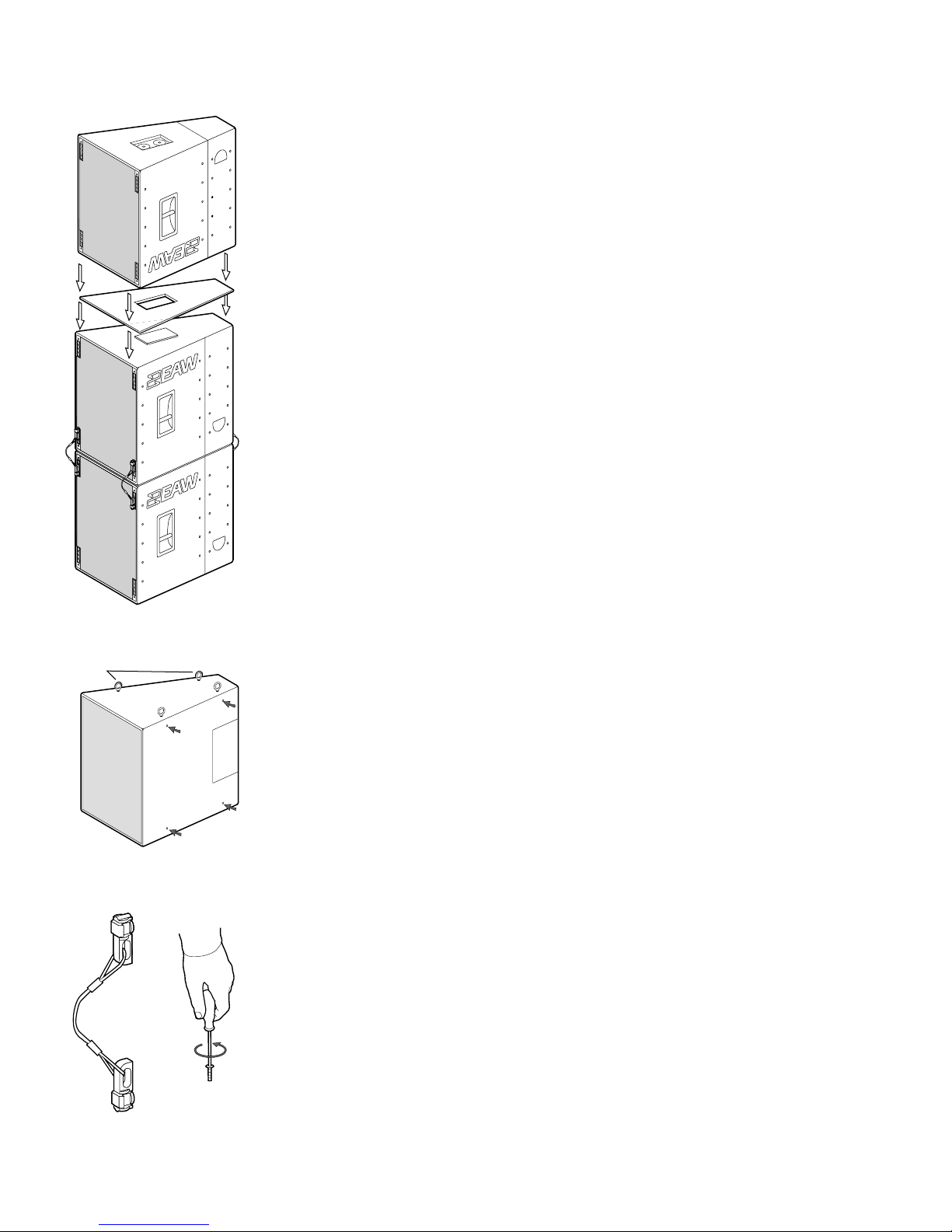
when stacked. This pad provides for a more secure stack. EAW recommends that fly hardware be used to provide additional stability. A crossed configuration of the cable links
allows for minimal slack, improving safety and stability. Stacked clusters should
also be strapped together to provide even greater stability.
In many venues, most notably theaters that do not permit flown arrays, inverted KF755s
will be used to provide upfill when stacked. This scenario forces enclosures to touch topto-top and, therefore, pad-to-pad. In order to prevent slippage and provide a more secure
stack, EAW has created a stacking plate (EAW P/N 980031)constructed of painted birch
plywood. The stacking
plate shares the KF700 Series footprint and provides a central
cutout that locks into pads on both adjoining enclosures.
5.3.3 SUSPENSION HARDWARE
WARNING: See Section 1.3 for information regarding rigging and suspending KF700
Series loudspeakers.
KF700(P and P-WP) Series installation versions utilize internal steel angles to provide a
total of sixteen (16) 3/8”-16 threaded mounting points (four each on the top, bottom
and sides). The enclosures ship with undercut 3/8-16 hardware that sits flush with the
enclosure walls. Replacement of factory-installed hardware with Grade 8 forged shoulder
eyebolts provides appropriate suspension points on an enclosure. The eyebolt manufacturer should be consulted for eyebolt working load limit specifications.
CAUTION: All four points on any given side should be utilized when hanging an
enclosure. Failure to use all four points can result in damage to the equipment, personal
injury, or death.
KF700(F) Series touring versions are equipped with two-position industry standard flytracks located in the front and rear corners. The aircraft grade aluminum track is attached
to the Baltic birch enclosure via internal angled steel that runs the full height of the enclosure. This construction is such that the enclosure bears no weight when flown. Each
KF700(F) Series touring version loudspeaker is shipped with four cable links described
above. These can be used for attaching the enclosures to fly bars as well as for attaching
vertically adjacent enclosures to each other. Enclosures should be connected using all
four available points (two front and two back) as depicted in the illustration.
Available fly bar manufacturer information can be obtained by contacting EAW.
FOUR EYE BOLTS INSTALLED INTO
TOP THREADED HANG POINTS
ARROWS INDICATE
SIDE HANG POINTS
FLY
CLIP/CABLE
INTERCONNECT
ASSEMBLIES
3/8-16 HARDWARE
WITH A 7/32 ALLEN WRENCH
REMOVING
THE
UNDERCUT
 Loading...