

Page 1
SPECIFICATIONS KF750F
DESCRIPTION
PERFORMANCE
One Main Street, Whitinsville, MA 01588 508 234 6158 Toll Free 800 992 5013 FAX 508 234 8251 info@eaw.com www.eaw.com
EAW products are continually improved. All specifications are therefore subject to change without notice. KF750F/2 pp October 2001 Printed in USA
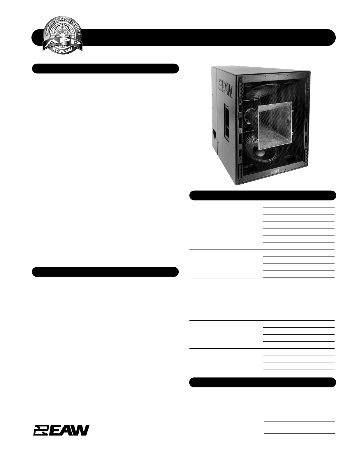
The KF750F 3-way tri-amplified full range system contains
many new EAW technologies that make it a powerful concert
touring sound reinforcement tool. Its Acoustic Singularity™
design aligns the three subsystems along a single axis so the
KF750 acts as a true point source, greatly reducing temporal
smearing of tr ansi en t even ts an d improvin g over all clarity an d
impact.
Since the large mid frequency horn contains both the high
and low frequency subsystems, the overall package is just
31-in high. Still, the KF750F provides consistent wideband
pattern control in both the vertical and horizontal planes.
The LF subsystem includes two vented 12-in woofers mounted in the MF horn’s upper and lower walls. This spaced configuration extends vertical directivity well into the LF passband to minimize midbass build up below the array.
The large MF horn loads a specially designed 10-in midrange
cone whose geometry exactly matches the rear of its phase
plug assembly. By developing the driver and phase plug as a
single unit, pathlength discontinuities within the MF passband have been eliminated without compromising the directional qualities of the source.
The 2-in exit/4-in voice coil HF compression driver is mounted on a 35° x 35° constant directivity horn mounted coaxially within the MF horn flare.
The KF750F’s 15°-per-side trapezoidal enclosure features
eight 4-position flytracks (four each front and rear) that
accept industry-standard flyclips.
The KF750F is designed to create arrays with optimized coverage in both the h orizontal an d vertical plan es to cover audience areas ranging from 200 to 80,000 people.
At just 31-in tall and 190 lb. per module, KF750F arrays are
smaller, lighter, more efficient and, therefore, more powerful
than those built with other systems. These smaller, lighter
arrays are easier to fly, require less truck space and permit
more open sight lines to cover any given venue.
The KF750F works with a companion downfill module, the
KF755F, to provide full range nearfield coverage below the
array. The KF750F’s smooth power response produces remarkably even SPL levels throughout the coverage area, allowing
it to be used for nearfield coverage when necessary.
Applications include:
Concert Tours Performing Arts Centers
Houses of Worship Theaters
APPLICATION
Frequency Response (Hz)
±3 db 48 Hz to 18 kHz
-10 dB 30 Hz
Axial Sensitivity (dB SPL, 1 Watt @ 1m)
LF 103
MF 109
HF 116
Impedance (Ohms)
LF 2x 8
MF 8
HF 8
Power Handling, (Watts Continuous)
LF 2x 600
MF 400
HF 200
Recommended High-Pass Frequency
24 dB/Octave 35 Hz
Calculated Maximum Output (dB SPL @ 1m)
LF Peak/Long Term 139/133
MF Peak/Long Term 141/135
HF Peak/Long Term 145/139
Nominal Coverage Angles, -6 dB points (degrees)
Horizontal 35
Vertical 35
PHYSICAL
Configuration 3-way, full range
Powering Tri-amplified
LF Subsystem 2x 12-in cones, vented
MF Subsystem 10-in cone, Radial Phase Plug™
horn-loaded
HF Subsystem 2-in exit/4-in voice coil
compression driver on CD horn
Page 2
SPECIFICATIONS KF750F
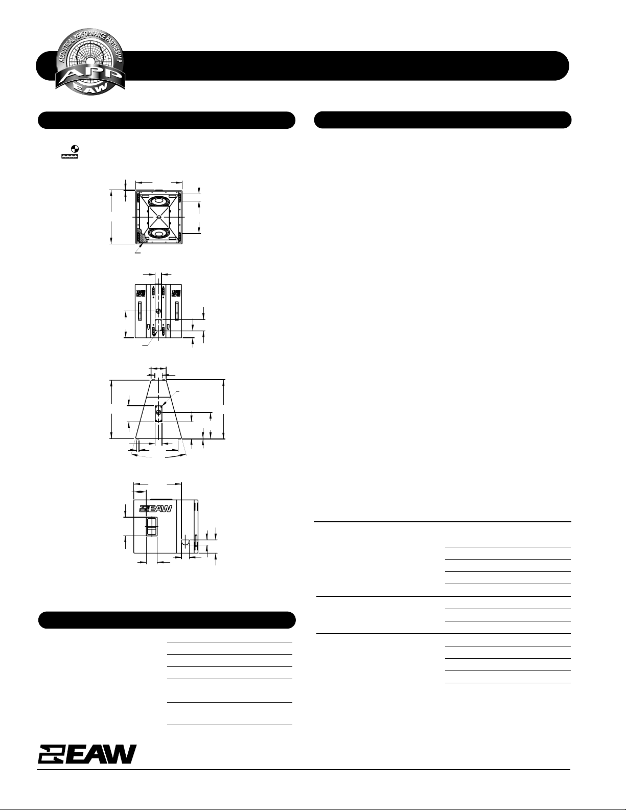
DIMENSIONAL DRAWING
A & E SPECIFICATIONS
One Main Street, Whitinsville, MA 01588 508 234 6158 Toll Free 800 992 5013 FAX 508 234 8251 info@eaw.com www.eaw.com
EAW products are continually improved. All specifications are therefore subject to change without notice. KF750F/2 pp October 2001 Printed in USA
Cabinet Type (shape) Trapezoidal
Enclosure Materials Baltic birch plywood
Finish Black polyurethane
Connectors 2x Neutrik NL8 Speakon
Suspension Hardware 8x 4-position flytrack
(4 each front and rear)
Grille Powder coated perforated steel,
foam backed
Dimensions inches millimeters
Height 31.0 787
Width (Front) 27.0 686
Width (Rear) 8.8 233
Depth 34.0 864
Trapezoid Angle 15 degrees per side
Weights pounds kilograms
Net Weight 190 86.5
Shipping Weight 200 91.0
Companion Systems
Sub Bass SB750F/SB1000e/KF940
Full Range Downfill KF755F
Accessories KF700 Series caster pallet
The three-way full ran ge loudspeaker system shall incorpor ate
2x 12-in LF transducers, a 10-in MF cone transducer and a 2in exit/4-in voice coil compression driver HF transducer.
The LF drivers shall be mounted in a vented enclosure tuned
for optimum low frequency response and separated vertically.
The MF driver shall be mounted on a large-format horn and
shall be coupled to a phase plug whose geometry exactly
matches that of the driver. The HF driver shall be loaded on a
constant directivity horn with a nominal coverage pattern of
35° (h) x 35° (v).
System frequency response shall vary no more than ±3 dB
from 48 Hz to 18 kHz measured on axis. The loudspeaker’s
subsystems (LF/MF/HF) shall produce a Sound Pressure Level
(SPL) of 103/109/116 dB SPL on axis at 1 meter with a power
input of 1 Watt, an d shall be capable of pr odu cing a peak output of 139/141/145 dB SPL on axis at 1 meter. The subsystems (LF/MF/HF) shall handle 2x 600/400/200 Watts of
amplifier power (continuous) and shall have nominal impedances of 2x 8/8/8 Ohms.
The loudspeaker enclosure shall be trapezoidal in shape. It
shall be constructed of multi-ply void-free cross-grain-laminated Baltic birch plywood and shall employ extensive internal bracing. It shall be finished in black catalyzed
polyurethane. Input connectors shall be a 2x Neutrik NL8
Speakon. A total of eight 4-position flytracks (4 each front
and rear) shall be provi d ed. The front of the loudspeaker shall
be covered with a powdercoated perforated steel grille.
The three-way full ran ge loudspeaker system shall be the EAW
model KF750F.
CABINET TO BE SYMMETRICAL ABOUT CENTERLINE DESIGNATIONS.
INDICATES CENTER OF BALANCE.
INDICATES FLY TRACK MOUNTING POINTS.
FRONT
DIMENSIONS APPLY
TO TOP AND BOTTOM
4X 18.88
8X 4.12
27.00
.38
C
L
GRILL PARTIALLY SHOWN
31.38
TOP/BOTTOM
(8.78)
4.00
4.44
15.25
22.90
9.25
9.81
STACK PAD
L
C
34.00
(8X.25)
30°
34.50
(8X 1.37)
7.75
27.80
4.50
3.00
7.28
6.44
10.87
SIDES
BACK
C
INPUT
6.63
3.63
L
15.50
4.00
510741 (1)
4/15/99
Manufacturing tolerances are +/- 0.13 and +/- 1°
PHYSICAL continued
 Loading...