

Page 1

Eastern Acoustic Works One Main S treet Whitinsville, MA01588 tel 800 992 5013 / 508 234 6158 fax 508 234 8251 www.eaw .com
EAW products are continually improved. All specifications are therefore subject to change without notice. Part Number: RDxxxx (A) KF730PSPEC Preliminary March 2004
KF730P Specifications group · M
FEATURES
•
Highest output to size ratio for small format line arrays
•
Large MF/HF horn and Phase Aligned™ LF drivers for
exceptional 1 10° horizontal pattern to 160 Hz
•
KF730 Wizard auto-designs flown and ground-stacked arrays
•
Included Splay Brackets fix the splay angles between enclosures
•
16 ohm inputs allow powering 8 KF730s with 2 amplifier channels
DESCRIPTION
The KF730P Series is a compact, fixed installation, line array
system that sets a performance benchmark above similar systems.
It delivers 3-way , KF Series performance in a flexible, easy-to-use
system that can deliver concert-level output in an exceptionally
wide range of venues. The KF730Pis an excellent solution for fixed
installation applications such as houses of worship, theatres, hotel
ballrooms, arenas, and concert halls. The system is also ideal for
supplemental coverage for larger line arrays, such as the KF760
Series. Such uses include audience side fill, delayed arrays for
balconies, and stage/performer coverage.
One large MF/HF horn fills the entire face of the enclosure, better
maintaining horizontal pattern control throughout the MF/HF
passband. The curved aperture MF loading slots effectively
move the MF acoustic origin further into the horn than physical
space permits. The side-mounted LF drivers provide a forwardfiring, figure eight type pattern. The drivers are spaced so that
the LF beamwidth matches the MF through crossover.
The KF730P input features barrier strip terminals. A separate
terminal strip is provided for loop-through connection for daisychaining additional KF730Ps.
The KF730P is configured using
the included KF730P Splay Angle Brackets to bolt the
enclosures together. This rigging system is fully comp atible with
the companion SB730Psubwoofer. Six year warranty .
3-WAY FULL-RANGE BI-AMP(passive MF/HF filter)
Performance is for a single KF730P . Array performance is determined using the KF730 Wizard.
See TABULARDATA notes for details
CONFIGURA TION
Subsystem
Transducer Loading
LF 2x 10 in cone Phase Aligned™
MF 2x 7 in cone Horn-loaded
HF 2x 1 in exit, 1.75 in voice Horn-loaded
coil neodymium
compression driver
Operating Mode
Amplifier Channels External Signal Processing
Bi-amp LF, MF/HF DSPw/2-way filters
PERFORMANCE
1
Operating Range 80 Hz to 20 kHz
Nominal Beamwidth
Horz 110°
Vert 12°
Axial Sensitivity (whole space SPL)
MF/HF 105 dB 230 Hz to 20 kHz
LF 91 dB 80 Hz to 230 Hz
Peak Sensitivity (whole space SPL)
MF/HF 112 dB 20 Hz to 20 kHz
LF 92 dB 20 Hz to 20 kHz
Input Impedance (ohms)
Nominal Minimum
MF/HF 16 15.9 @ 680 Hz
LF 16 15.1 @ 250 Hz
Recommended High Pass Filter
High Pass =>80 Hz, 24 dB/octave
Accelerated Life Test
2
MF/HF 75 V 350 W @ 16 ohm
LF 106 V 700 W @ 16 ohm
Calculated Axial Output Limit (whole space SPL)
Average Peak
MF/HF 130 dB 136 dB
LF 119 dB 125 dB
ORDERING DA T A
Description Part Number
KF730PBlack Line Array Loudspeaker 0007663
KF730PWhite Line Array Loudspeaker 0009645
Optional Accessories
KF730P/SB730PFly-Bar 0008108
KF730PPull-Bar 0008363
1 T o achieve specified performance, the listed external signal processing with EA W-provided settings is required.
2 For recommendations to select power amplifier size refer to : “HOW MUCH AMPLIFIER POWER DO I NEED?” on the EA W web site.
Page 2

Eastern Acoustic Works One Main S treet Whitinsville, MA01588 tel 800 992 5013 / 508 234 6158 fax 508 234 8251 www.eaw .com
EAW products are continually improved. All specifications are therefore subject to change without notice. Part Number: RDxxxx (A) KF730PPreliminary March 2004
KF730P Specifications group · M
ENCLOSURE
Material Baltic birch plywood
Finish Wear resistant textured black paint
Grille Powder-coated perforated steel
NOTES:
2.42
INPUT
ACCESS PANEL
L
C
5.00
9.134.00
EASTERN ACOUSTIC W ORKS
BACK
KF730P
L
C
(9.83)
A
1.59
12.10
15.19
3/8-16 THREADED HOLE (PI ANGLE) .
3/8-16 THREADED HOLE (STRAPPING).
1. SYMBOL INDICATES MOUNTING POINT,
2. SYMBOL INDICATES MOUNTING POINT,
3. SYMBOL INDICATES CENTER OF BALANCE.
4. WEIGHT APPROX. 78 LB.
12.17
5. SHIPPING WEIGHT APPROX. 86 LB.
1.73
(2.01)
A
7.69
4.69
L
C
6.00
7.23
10.23
12°
2X HANDLE
7.66
RIGHT SIDE
PRODUCTION
DIMENSIONS APPLY TO BOTH SIDES
L
C
28.75
24.72
VIEW A-A
TOP AND BOTTOM
DIMENSIONS APPLY TO
8.25
13.03
FRONT
GRILLE PARTIALLY SHOWN
Page 3
Eastern Acoustic Works One Main S treet Whitinsville, MA01588 tel 800 992 5013 / 508 234 6158 fax 508 234 8251 www.eaw .com
EAW products are continually improved. All specifications are therefore subject to change without notice. Part Number: RDxxxx (A) KF730PPreliminary March 2004
KF730P Specifications group · M
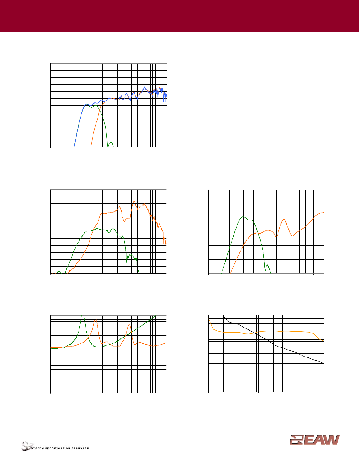
PERFORMANCE DA T A See NOTES GRAPHIC DATANotes for details
Frequency Response: Processed Bi-amplified
LF = green MF/HF = orange Complete = blue
SPL(dB)
Frequency Response: Unprocessed
LF = green MF/HF = orange
SPL(dB)
Frequency Response: Digital Signal Processor
LF = green MF/HF = orange
dB re 0.775 V
Beamwidth (-6 dB SPLPoints)
Horizontal = orange Vertical = black
Degrees
Impedance Magnitude
LF = green MF/HF = orange
Ohms
120
110
100
90
80
70
60
100
10
1
400
100
10
1
100 1000 20000
Frequency (Hz)
10 100 1000 20000
Frequency (Hz)
120
110
100
90
80
70
60
20
10
0
-10
-20
-30
-40
10 100 1000 20000
Frequency (Hz)
10 100 1000 20000
Frequency (Hz)
10 100 1000 20000
Frequency (Hz)
120
110
100
90
80
70
60
10 100 1000 20000
Frequency (Hz)
Page 4
Eastern Acoustic Works One Main S treet Whitinsville, MA01588 tel 800 992 5013 / 508 234 6158 fax 508 234 8251 www.eaw .com
EAW products are continually improved. All specifications are therefore subject to change without notice. Part Number: RDxxxx (A) KF730PPreliminary March 2004
KF730P Specifications group · M
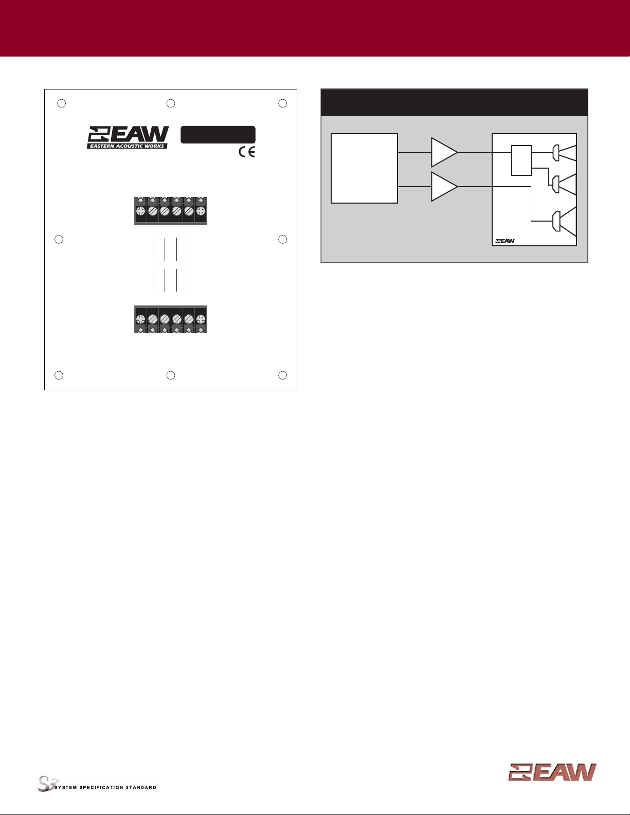
INPUT P ANEL
NOTES
TABULAR DA T A
1. Primary Measurement/Data Processing System: FChart: proprietary EA W software.
2. Secondary Measurement System: Brüel & Kjær 2012.
3. Microphone Systems: Earthworks M30; Brüel & Kjær 4133
4. Measurements: Dual channel FFT ; length: 32 768 samples; sample rate: 48 kHz; logarithmic sine wave sweep.
5. Measurement System Qualification (includes all uncertainties):SPL: accuracy +/-0.2 dB @ 1 kHz, precision +/-0.5 dB 20 Hz to 20 kHz, resolution 0.05 dB; Frequency: accuracy +/-1 %,
precision +/-0.1 Hz, resolution the larger of 1.5 Hz or 1/48 octave; Time: accuracy +/-10.4 µs, precision +/-0.5 µs, resolution 10.4 µs; Angular: accuracy +/-1°, precision +/-1°, resolution 1°.
6. Environment: Measurements time-windowed and processed to eliminate room effects, approximating an anechoic environment. Dat a processed as anechoic or fractional space, as noted.
7. Measurement Distance: 7.6 to 8.0 m. Data is referenced to other distances using the Inverse Square Law .
8. Volts: Measured rms value of the test signal.
9. Watts: Per audio industry practice, “loudspeaker watts” are calculated as voltage squared divided by rated nominal impedance. Thus, these are not True Watt units of energy as defined by
International Standard.
10. SPL: (Sound Pressure Level) Equivalent to the average level of a signal referenced to 0 dB SPL= 20 microPascals.
11. Subsystem: This lists the transducer(s) and their acoustic loading for each passband. Sub Bass = Subwoofer, LF = Low Frequency, MF = Mid Frequency , HF = High Frequency .
12. Operating Mode: User selectable configurations. Between system elements, a comma (,) = separate amplifier channels; a slash (/) = single amplifier channel. DSP= Digital Signal Processor.
IMPORTANT: To achieve the specified performance, the listed external signal processing must be used with EA W-provided settings.
13. Operating Range: Range where the processed Frequency Response stays within -10 dB SPLof the power averaged SPL within this range; measured on the geometric axis. Narrow band
dips are excepted.
14. Nominal Beamwidth: Design angle for the -6 dB SPLpoints, referenced to 0 dB SPL as the highest level.
15. Axial Sensitivity: Power averaged SPLover the Operating Range with an input voltage that would produce 1 W at the nominal impedance; measured with no external processing on the
geometric axis, referenced to 1 m.
16. Peak Sensitivity:Highest axial SPL measured within the 20 Hz to 20 kHz bandpass with an input voltage that would produce 1 W at the nominal impedance; measured with no external
processing on the geometric axis, referenced to 1 m.
17. Nominal Impedance: Selected 4, 8, or 16 ohm resistance such that the minimum impedance point is no more than 20% below this resistance over the Operating Range.
18. Accelerated Life T est: Maximum test input voltage applied with an EIA-426B defined spectrum; measured with recommended signal processing and Recommended Protection Filter .
19. Calculated Axial Output Limit: Highest average and peak SPLs possible during the Accelerated Life T est. The Peak SPLrepresents the 2:1 (6 dB) crest factor of the Life T est signal.
20. Recommended High Pass Filter: This should be used to help protect the loudspeaker from excessive input signal levels below the Operating Range.
GRAPHIC DAT A
1. Resolution:To remove insignificant fine details, 1/12 octave cepstral smoothing was applied to acoustic frequency response and 1/3 octave cep stral smoothing was applied to the
beamwidth and impedance data. Other graphs are plotted using raw data.
2. Frequency Responses:The variation in acoustic output level with frequency for a constant input signal of 2 volts (4 ohm nominal impedance), 2.83 volts (8 ohm nominal impedance),
or 4 volts (16 ohm nominal impedance) referenced to a distance of 1 m. For processed systems, this applies where the processor gain is 0 dB in the Processor Frequency Response graph.
3. Processor Response:The variation in output level with frequency for a constant input signal of 0.775 V = 0 dB reference.
4. Beamwidth:Average angle for each 1/3 octave frequency band where, starting from the rear of the loudspeaker, the output first reaches -6 dB SPLreferenced to 0 dB SPL as the highest
level. This method means the output may drop below -6 dB SPLwithin the beamwidth angle. Referenced to 20 m.
5. Impedance: Variation in impedance magnitude, in ohms, with frequency without regard to voltage/current phase. This means the impedance values may not
be used to calculate True Watt s (see 9 above).
SIGNAL DIAGRAM
LEGEND
DSP: User-supplied Digital Signal Processor for EQ, crossover, and delay .
HPF: High Pass Filter for crossover or Recommended High Pass Filter.
LPF: Low Pass Filter for crossover.
LF/MF/HF: Low Frequency / Mid Frequency / High Frequency.
PWR AMP: User-supplied Power Amplifier.
XVR: Passive LPFs, HPFs, and EQ integral to the loudspeaker.
WHITINSVILLE, MA USA
Before suspending, read all rigging warnings in the Owner's Manual.
S/N
DANGER
LF MF/HF
--
--
+
LOOP THRU
LF MF/HF
--
--
+
KF730P
+
+
3-Way, Bi-Amp (LF, MF/HF)
DSP
EQ
DELAY
HPF/LPF
AMP
AMP
XVR
HF
MF
LF
 Loading...