

A
C
O
U
S
T
I
C
A
L
P
E
R
F
O
R
M
A
N
C
E
P
A
R
T
N
E
R
S
H
I
P
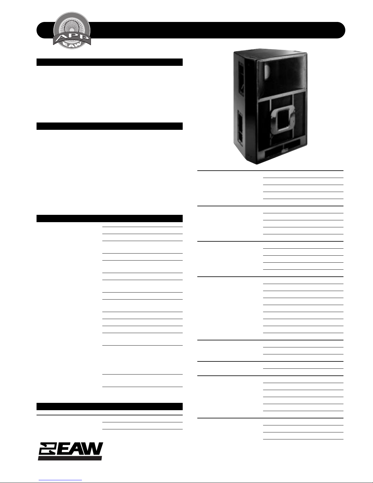
TECHNICAL SPECIFICATIONS KF695e
DESCRIPTION
A 3-way full range system in a ven ted trapezoi dal enclosur e .
Includes a 15-in woofer in a wave guide cavity with ARC™
device, a horn-loaded 10-in midrange cone and a 2-in exit
compression driver m ounted coaxially in the wave guid e cavity
on a 90 x 40 constant directivity horn. Powering mode is
switchable: biamplified (passive MF/HF crossover) or
triamplified.
APPLICATIONS
The KF695e Virtual Array system’s true 3-way design dramatically improves the quality of vocal reproduction while
its cone-driven midrange horn and horn loaded woofer extend pattern control into the lower octaves. Universal suspension hardware (flytrack with integral 3/8"-16 mounting
point) supports permanen t or portable applications . Six year
warranty .
Applications include:
Band PA Ballroom Events
Corporate Events Convention Centers
Large HOW’s Live Music Club
DESCRIPTIVE DATA
Part Number 999020
Product Group S
LF Subsystem & Loading 1x 15-in in a Wave Guide Cavity
with ARC™ Device
MF Subsystem & Loading 1x 10-in Horn-Loaded Cone
HF Subsystem & Loading 1x 2-in Exit Compression Driver on
Constant Directivity Horn
System Configuration 3-way, Full Range
Powering Configuration(s) Switchable: Biamplified (passive
MF/HF crossover) or Triamplified
Controls (switches, knobs) Powering Mode Switch
Recommended High-Pass
Frequency (24 dB/Octave) 45Hz
Cabinet Type (shape) Trapezoidal
Enclosure Materials Baltic Birch Plywood
Finish Black Catalyzed Polyurethane
Connectors I each male and female AP6
I each male and female AP4
Suspension Hardware (6) 3-Position flytrack with
integral 3/8”-16 suspension points
(3 each top and bottom) plus (5)
3/8”-16 threaded suspension
points (2 per side, 1 on back)
Grill Vinyl Coated Perforated Steel,
Foam Backed
Options 179001 Flyclip with ring
179002 Flyclip with hook
NOMINAL DATA
Frequency Response (Hz)
±3 db 65Hz to 17kHz
-10 dB 50Hz
Axial Sensitivity (dB SPL/1 Watt/1m)
Biamped MF/HF 107
LF 100
MF 107
HF 107
Impedance (Ohms)
Biamped MF/HF 8
LF 8
MF 8
HF 8
Power Handling, AES Standard (Watts)
Biamped MF/HF 400
LF 1000
MF 400
HF 200
Calculated Maximum Output (dB SPL, @ 1m)
Biamped MF/HF Peak 139.0
LF Peak 136.0
MF Peak 139.0
HF Peak 136.0
Biamped MF/HF Long term 133.0
LF Long Term 130.0
MF Long Term 133.0
HF Long Term 130.0
Nominal Coverage Angle / -6 dB points (degrees)
Horizontal 90
Vertical 40
Recommended Complementary Systems
Sub SB600e/SB625P
Dimensions inches millimeters
Height 33.22 844
Width (Front) 25.63 651
Width (Rear) 12.75 324
Depth 19.75 502
Trapezoid Angle 23 degrees per side
Weights pounds kilograms
Net Weight 147 66.9
Shipping Weight 162 73.7
EASTERN ACOUSTIC WORKS
One Main Street, Whitinsville, MA 01588 • (508) 234 - 6158 • FAX (508) 234 - 8251 • Email info@eaw.com • Web http://www.eaw.com
EAW products are continually improved. All specifications are therefore subject to change without notice. • PUB# KF695e-888047 (A)/2 pp/1/29/99 • Printed In USA
A
C
O
U
S
T
I
C
A
L
P
E
R
F
O
R
M
A
N
C
E
P
A
R
T
N
E
R
S
H
I
P
TECHNICAL SPECIFICATIONS KF695e
3
9
DIMENSIONAL DRAWING ARCHITECTURAL SPECIFICATIONS
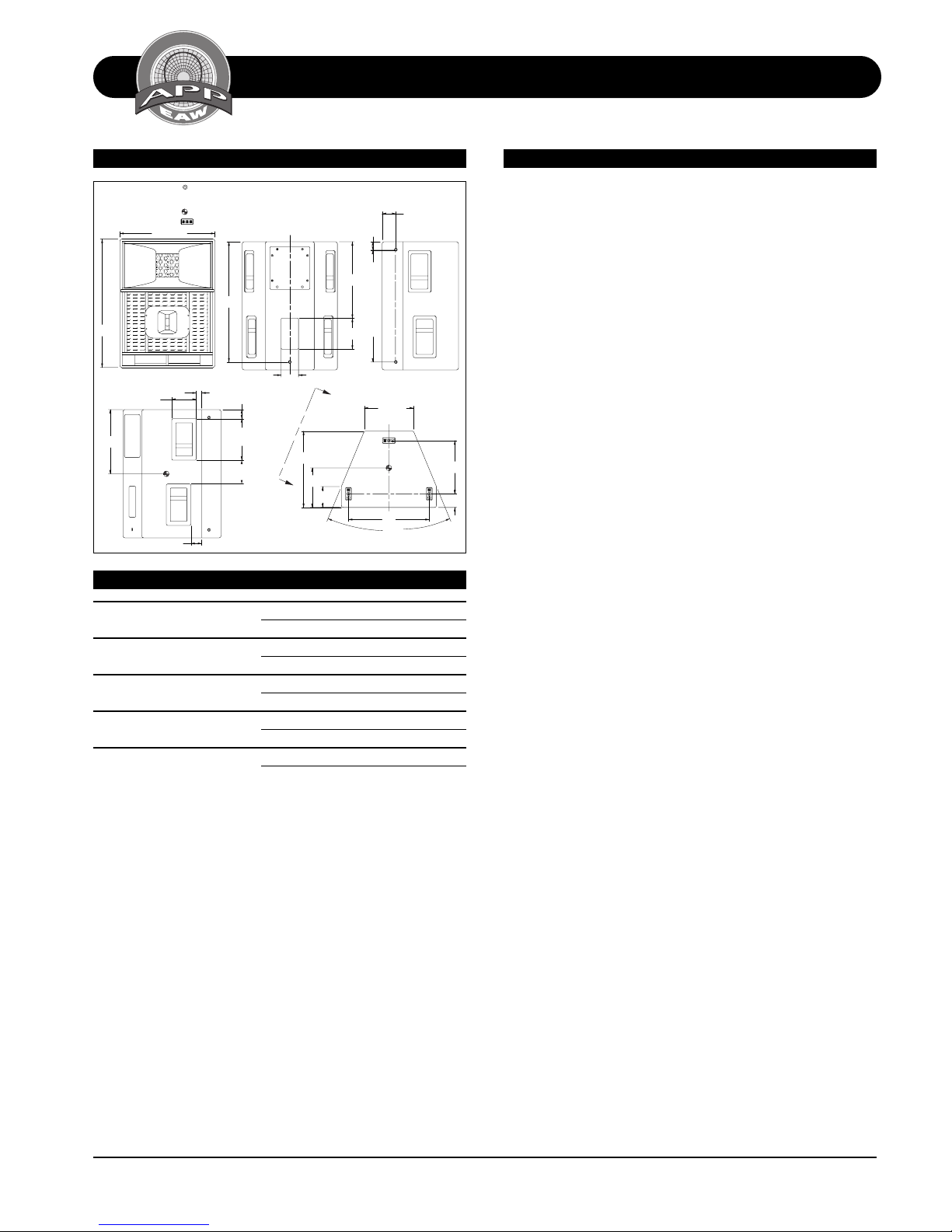
DIMENSIONAL DRAWINGS
MOUNTING POINT, 3/8"-16 THREADED HOLE
KF695e
33.21
6.38 2X
BOTH SIDES
16.63
510339 EXP 4/1/97 SHB
VIEW A-A
ALL DIMENSIONS IN INCHES UNLESS OTHERWISE SPECIFIED.
CABINET SYMETRICAL ABOUT ITS CENTERLINES.
CENTER OF GRAVITY.
24.63
FRONT
FLY TRACK.
31.15
1.39
2.79
BOTH SIDES
2.36
10.75 2X
BOTH SIDES
6.14
BOTH SIDES
BOTH SIDES
BACK
BOTH SIDES
C
L
A
4.50
19.75
10.24
BOTH SIDES
19.82
8.00
A
5.42
TOP & BOTTOM
SERVICE ITEMS
LF: Complete Cone Driver
EAW Part No. 804036
MF: Complete Cone Driver
EAW Part No. 804022
HF: Complete Compression Driver/Tweeter
EAW Part No. 803010
HF: Diaphragm Assembly
EAW Part No. 251007
Filter/Crossover Network: Complete Assembly
EAW Part No. 201755
2.19
BOTH SIDES
28.96
3.53
(12.75)
C
L
20.94
45.0°
BOTH SIDES
SIDE
13.7
3.5
The three-way full ran g e lou dspeak er system s shall incorporate a 15-in LF transd ucer, a 10-in cone MF tran sdu cer and a
2-in exit compression driver HF transducer.
The LF driver shall be mounted in a wave guide cavity for
optimum low frequency directivity. The MF driver shall be
loaded into a midrange horn constructed of 3mm birch plywood reinforced with high density polyurethane foam. The
MF horn shall incorporate a phase/displacement plug. The
HF driver shall be coaxially mounted in the woofer cavity
and shall be loaded on a constant directivity horn with a
nominal coverage pattern of 90° (h) x 40° (v). A device to
absorb refracted HF energy shall be installed behind the HF
section. An internal passive filter n etwork shall provide fourth
order acoustical crossover between the mid and high frequency sections in biamped mode and system equalization.
System frequency response shall vary no more than ±3 dB
from 65 Hz to 17 kHz measured on axis. In biamped mode,
the mid/high section shall produce a Sound Pressure Level
(SPL) of 107 dB SPL on axis at 1 meter with a power input of
1 Watt, and shall be capable of producing a peak output of
139 SPL on axis at 1 meter. It shall handle 400 Watts of
amplifier power (AES Standard) and shall have a nominal
impedance of 8 Ohm s. The LF section shall produce a Sound
Pressure Level (SPL) of 100 dB SPL on axis at 1 m eter with a
power input of 1 Watt, and shall be capable of producing a
peak output of 136 SPL on axis at 1 meter. It shall handle
1000 Watts of amplifi er power (AES Standard) an d shall have
a nominal impedance of 8 Ohms.
In triamped mode, the low frequency and high frequency
sections shall meet all biamped mode performance criteria.
In addition, the mi drange fr equency section in triamped m ode
shall produce a Soun d Pressure Level (SPL) o f 107 dB SPL on
axis at 1 meter with a power input of 1 Watt, and shall be
capable of producing a peak output of 139 SPL on axis at 1
meter. It shall handle 400 Watts of amplifier power (AES
Standard) and shall have a nominal impedance of 8 Ohms.
The loudspeaker enclosure shall be rectangular in shape. It
shall be constructed of 15mm thi ckness void-free cr oss-grainlaminated Baltic birch plywood and shall employ extensive
internal bracin g. It shall be finished in black catalyzed polyurethane. Input connectors shall be one each male and female AP4 plus one each male and female AP6. The system
shall include a switch allowin g it to be operated in biamp or
triamp powering mode. A total of six 3-position flytracks
with integral 3/8"-16 thread ed mountin g points (3 each top
and bottom) plus five 3/8"-16 threaded m ountin g points (2
per side, 1 back) shall be provided. The front of the loudspeaker shall be covered with a vinyl coated perf orated steel
grill backed with open cell foam to protect against dust.
The three-way full ran ge loudspeaker shall be th e EAW m odel
KF695e.
Acoustic Performance Partnership Eastern Acoustic Works KF695e
One Main Street, Whitinsville MA, 0158 8 USA • Phone 508/234-6158 • Toll Free 800/992-5013 • Fax 508/234-8251 • Web http://www.eaw.com • email info@eaw .com
 Loading...