

EAW JFX590 User Manual
SPECIFICATIONS JFX590
One Main Street, Whitinsville, MA 01588 508 234 6158 Toll Free 800 992 5013 FAX 508 234 8251 info@eaw.com www.eaw.com
EAW products are continually improved. All specifications are therefore subject to change without notice. JFX590/0004643/2 pp September 2002 Printed in USA
Part Number 0002887
System Configuration 2-way, full-range
Powering Switchable: Passive LF/HF
crossover or bi-amplified
LF Subsystem 1x 15-in, vented
HF Subsystem 1x 1.4-in exit/3-in voice coil
neodymium compression driver
on CD horn
Controls (switches, knobs) Powering mode switch
Recommended High-Pass
Frequency (24 dB/octave) 55 Hz
Enclosure Materials
Exterior grade Baltic birch plywood
Finish Wear resistant textured black paint
Connectors 2x Neutrik NL4 Speakon
Hardware Pole mount cup (bottom); 2x 3-
position fly track (bottom); 1x
11-position fly track (top); 4x
5/16”-18 suspension points for
Omnimount Series 300 (rear)
Grille Powder coated perforated steel,
foam backed
Frequency Response (1 W @ 1 m)
±3 dB 80 Hz to 15 kHz
-10 dB 55 Hz
Axial Sensitivity (dB SPL, 1 W @ 1 m)
Full Range 98
LF 98
HF 104
Impedance (Ohms)
Full Range 8
LF 8
HF 8
Power Handling (Watts, continuous)
Full Range 500
LF 800
HF 200
Calculated Maximum Output (dB SPL @ 1 m)
Full Range Peak 131
LF/HF Peak 133/133
Full Range Long Term 125
LF/HF Long Term 127/127
Nominal Coverage Angle / -6 dB points (degrees)
Horizontal 90
Vertical 45
PERFORMANCE
• Ideal size and performance for rigorous all-purpose use
• Wide 90° coverage optimized for use in stand-alone
applications
• HF compression driver and vented LF for fully professional
performance
• Asymmetric enclosure provides multiple mounting angles
• Pole mount cup & fly track, plus Omnimount®
Series 300 or similar mounting points
• Passive or bi-amplified operating modes
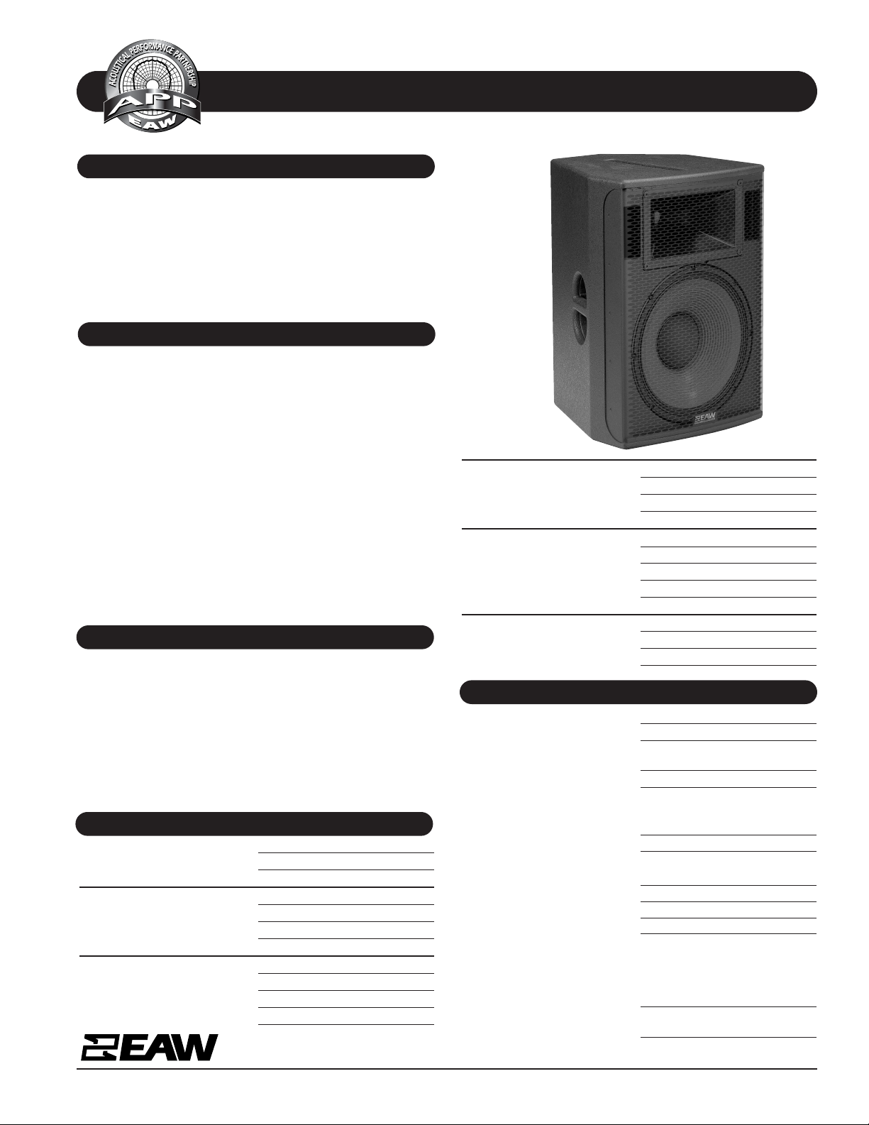
The JFX590 is a 2-way multi-purpose loudspeaker. Its multifunctional design adds considerably to its value as a fullrange loudspeaker. Combining high output an d n atur al r epr oduction, it is specifically outfitted to serve in a variety of
both portable and permanent applications. The asymmetric
enclosure provides typical angles needed for ceiling and wall
mounting as well as for stage monitor operation. For permanent installation, enclosure hardware includes mounting
points for an Omnimount® Series 300 or similar bracket and
fly track for suspension. Provisions for portable use include
a pole mount cup, top/bottom fly track for rigging, and handles integral to the enclosure that facilitate handling and
transport. The JFX590 is particularly suitable as a near field
main loudspeaker or as a fill/delay element in larger systems.
While the JFX590 is well suited as is for many applications,
the addition of a subwoofer expands its capabilities for more
demanding applications such
as for houses of worship, theaters,
and band PA. Six year warranty.
• Portable systems or permanent installations
• Wall and ceiling mountings
• Ideal size and output for wide range of
program material
• Main PA reinforcement in medium- to
large-sized spaces
• Downfill for flown clusters
• High SPL stage lip / delay fill
• A/V and/or surround sound installations
• Voice & F/X reinforcement in themed attractions
FEATURES
APPLICATION
DESCRIPTION
PHYSICAL
SPECIFICATIONS JFX590
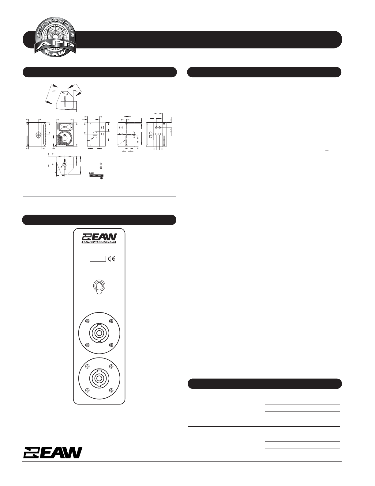
DIMENSIONAL DRAWING
A & E SPECIFICATIONS
One Main Street, Whitinsville, MA 01588 508 234 6158 Toll Free 800 992 5013 FAX 508 234 8251 info@eaw.com www.eaw.com
EAW products are continually improved. All specifications are therefore subject to change without notice. JFX590/0004643/2 pp September 2002 Printed in USA
Manufacturing tolerances are +/- 0.13 and +/- 1°
INPUT PANELS
PHYSICAL continued
Dimensions inches millimeters
Height 25.50 648
Width (front) 18.00 457
Width (rear) 6.25 159
Depth 19.00 483
Weights pounds kilograms
Net Weight 80 36.4
Shipping Weight 89 40.5
The 2-way full-range loudspeaker shall incorporate a 15-in LF
cone and a 3-in voice coil HF compr ession driver. The LF cone
shall be mounted in a vented enclosure tuned for optimum
low frequency response. The HF driver shall be loaded on a
1.4-in exit constant directivity horn with a nominal
beamwidth of 90 (H) x 45 (V) degrees. An internal passive
crossover network shall offer either passive or bi-amplified
operation, configur able vi a a power mod e switch on th e input
panel.
System frequency response shall vary no more than +
3 dB
from 80 Hz to 15 kHz measured on axis . When amplifi ed usin g
the internal passive crossover network, the loudspeaker shall
produce a sound pressure level of 98 dB SPL on axis at 1
meter with a power input of 1 watt, and shall be capable of
producing a peak output of 131 dB SPL on axis at 1 meter. It
shall handle 500 watts of amplifier power and shall have a
nominal impedan ce of 8 ohms . When bi-amplifi ed, the LF section shall produ ce a soun d pr essur e level o f 98 dB SPL on axis
at 1 meter with a power input of 1 watt, and shall be capable of producing a peak output of 133 dB SPL on axis at 1
meter. It shall handle 800 watts of amplifier power and shall
have a nominal impedance of 8 ohms. The HF section shall
produce a sound pressure level of 104 dB SPL on axis at 1
meter with a power input of 1 watt, and shall be capable of
producin g a peak output of 133 dB SPL on axis at 1 meter. It
shall handle 200 watts of amplifier power and shall have a
nominal impedance of 8 ohms.
The loudspeaker enclosure shall be irregularly trapezoidal in
shape. It shall be constructed of exterior grade Baltic birch
plywood and shall employ extensive internal bracing. It shall
be finished in wear-resistant te xtured black paint. Input connectors shall be 2x Neutrik NL4 Speakon wired in parallel. It
shall include a pole mount cup and handles integral to the
enclosure. One 11-position fly track and two 3-position fly
tracks shall be provided on the top and bottom of the enclosure respectively. Four 5/16"-18 thread ed mountin g points f or
use with an Omnimount® Series 300 (or similar) shall be provided on the rear of the enclosure. The front of the loudspeaker shall be covered with a foam backed, powder coated
perforated steel grille.
The 2-way full-range loudspeaker shall be the EAW model
JFX590.
C
INPUT
A
B
B
L
C
13.21
8.06
TOP
8.51
A
13.21
8.51
BOTTOM
TOP HAT
C
L
12.59
5.50
10.57
BACK
1.88
2.50
2.72
6.26
2.59
1.46
VIEW A-A
(13.93)
2X
HANDLE
0002888 (A) 8/12/02
19.00
2.81
(9.06)
6.13
8.02
GRILLE PARTIALLY SHOWN
22.5°
45°
18.00
VIEW B-B
2X 3.44
FRONT
8.75
L
2X 6.88
8.50
22.58
25.50
12.00
6.50
4.50
NOTES:
1. SYMBOL INDICATES MOUNTING POINT, 3/8-16
THREADED HOLE (PI ANGLE)
2. SYMBOL INDICATES MOUNTING POINT, 5/16-18 T-NUT
FOR OMNI MOUNT
SERIES 300.
3. SYMBOL INDICATES 3.00 X 1.35 FLY TRACK.
4. SYMBOL INDICATES 11.00 X 1.35 FLY TRACK.
5. SYMBOL INDICATES CENTER OF BALANCE.
6. WEIGHT APPROX. 80 LBS.
7. SHIPPING WEIGHT APPROX. 89 LBS
9.96
RIGHT SIDE
WHITINSVILLE, MA USA
JFX590
S/N
FULL-RANGE
PIN 1--...LF-PIN 1+...LF+
PIN 2--...HF-PIN 2+...HF+
NEUTRIK
NEUTRIK
NL 4 MPR
PASSIVE
PIN 1--...--
PIN 1+...+
BI-AMP
NEUTRIK
NEUTRIK
NL 4 MPR
 Loading...