

Page 1
A
C
O
U
S
T
I
C
A
L
P
E
R
F
O
R
M
A
N
C
E
P
A
R
T
N
E
R
S
H
I
P
TECHNICAL SPECIFICATIONS FL103
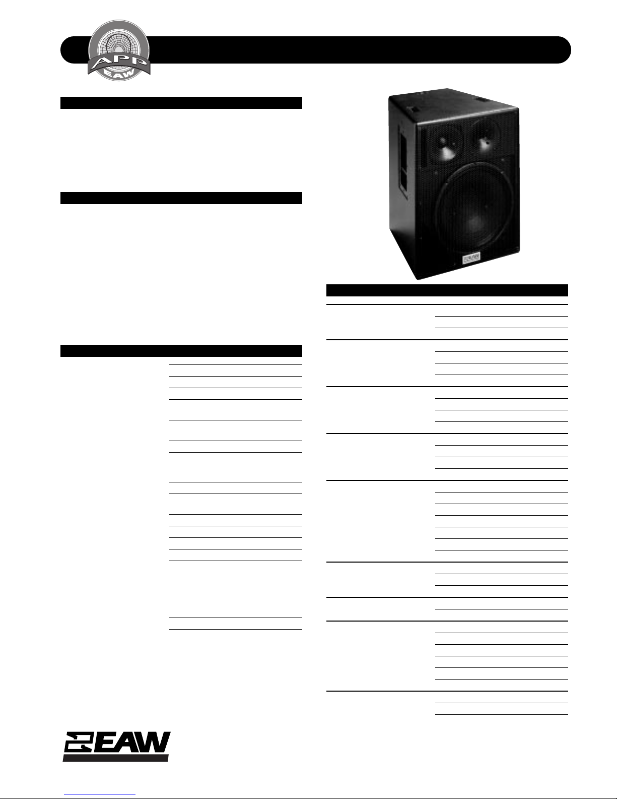
DESCRIPTION
A 3-way full range system in a d u al vent, trapezoidal enclosure. In cludes a 15-in woofer (ven ted), a 7-in midran ge cone
(separated vented subenclosure) and a 1-in exit compression driver on a W ave Gui de Plate™. Powering mode is switchable: passive (3-way crossover) or biamplified (passive MF/
HF crossover).
APPLICATIONS
The FL103 delivers extr emely high output an d studio fi delity
from a compact enclosure. True 3-way design dramatically
improves the quality o f speech reprod uction. Mi dran ge venting smooths response at LF/MF crossover. Low “Q” provides
exception ally natur al repr odu ction in perm anen t or portable
applications d emanding the highest quality sound. Comprehensive mounting/suspension hardware. Six year warranty.
Applications include:
Concert Halls Recital Halls
Theaters MultiMedia
Small HOW’s Live Music Club
DESCRIPTIVE DATA
Part Number 999066
Product Group J
LF Subsystem & Loading 1x 15-in, Vented
MF Subsystem & Loading 1x 7-in Cone in Vented
Subenclosure
HF Subsystem & Loading 1x 1-in Exit Compression Driver on
Wave Guide Plate™
System Configuration 3-way, Full Range
Powering Configuration(s) Switchable: Full Range (passive LF/
MF/HF crossover) or Biamplified
(passive MF/HF crossover)
Controls (switches, knobs) Powering Mode Switch
Recommended High-Pass
Frequency (24 dB/Octave) 30Hz
Cabinet Type (shape) Trapezoidal
Enclosure Materials Baltic Birch Plywood
Finish Black Catalyzed Polyurethane
Connectors 2 Neutrik NL4 Speakon
Suspension Hardware 6x 3-position flytracks (2 each on
top, bottom and back), 12x 3/8"16 threaded mounting/suspension
points (3 each top and bottom, 2
each sides and back)
stand mount cup (bottom)
Grill Vinyl Coated Perforated Steel
Options CCEP Config MX200i-FL103
(biamped mode)
MX300i-FL103 (w/ SB528)
MX300i-FLS18 (w/ SB180)
179001 Flyclip with ring
179002 Flyclip with hook
NOMINAL DATA
Frequency Response (Hz)
±3 db 50Hz to 18kHz
-10 dB 38Hz
Axial Sensitivity (dB SPL/1 Watt/1m)
Full Range 95
Biamped MF/HF 95
Biamped LF 95
Impedance (Ohms)
Full Range Passive 8
Biamped MF/HF 8
Biamped LF 8
Power Handling, AES Standard (Watts)
Full Range 500
Biamped MF/HF 500
Biamped LF 800
Calculated Maximum Output (dB SPL, @ 1m)
Full Range Peak 128.0
Biamped MF/HF Peak 128.0
Biamped LF Peak 130.0
Full Range Long Term 122.0
Biamped MF/HF Long term 122.0
Biamped LF Long Term 124.0
Nominal Coverage Angle / -6 dB points (degrees)
Horizontal 100
Vertical 100
Recommended Complementary Systems
Sub SB180/SB528
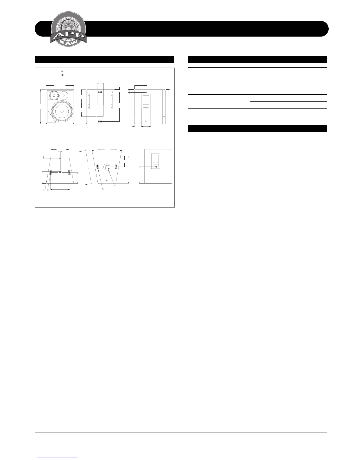
Dimensions inches millimeters
Height 24.625 625
Width 19.75 502
Depth 19.75 502
Back Width 12.75 324
Trapezoid Angle 10 degrees per side
Weights pounds kilograms
Net Weight 111 50.5
Shipping Weight 118 53.7
EASTERN ACOUSTIC WORKS
One Main Street, Whitinsville, MA 01588 • (508) 234 - 6158 • FAX (508) 234 - 8251 • Email info@eaw.com • Web http://www.eaw.com
EAW products are continually improved. All specifications are therefore subject to change without notice. • PUB# FL103-888029 (A)/2 pp/1/29/99 • Printed In USA
Page 2
A
C
O
U
S
T
I
C
A
L
P
E
R
F
O
R
M
A
N
C
E
P
A
R
T
N
E
R
S
H
I
P
TECHNICAL SPECIFICATIONS FL103
DIMENSIONAL DRAWING SERVICE ITEMS
DIMENSIONAL DRAWINGS
FL103
24.63
FRONT
2.06 TYP
.31
8.55
1.84 TYP
510012
EXP 4/26/96 SHB
1. INDICATES MOUNTING POINT, 3/8"-16 THREADED HOLE.
2. INDICATES CENTER OF BALANCE.
3. "TOP HAT" CONNECTOR FOR ULTIMATE BRAND STAND.
19.75
11.25
8.00
4.50
C
L
1.84 REF
20.94
2.06 REF
20.50
5.00
BACK
12.75
C
L
TOP
A
7.81 TYP
A
13.24 TYP REF
20°
C
L
FLYTRACK
BOTTOM
7.81
19.75
SEE NOTE 3
12.16
8.32
6.44
SIDE
VIEW A-A
3.13
10.81
LF: Complete Cone Driver
EAW Part No. 804055
MF: Complete Cone Driver
EAW Part No. 804050
HF: Complete Compression Driver/Tweeter
EAW Part No. 803001
Filter/Crossover Network: Complete Assembly
EAW Part No. 225068
ARCHITECTURAL SPECIFICATIONS
The three-way full ran g e lou dspeak er system s shall incorporate a 15-in LF transducer, a 7-in cone MF transducer and a
1-in exit compression driver HF transducer.
The LF driver shall be mounted in a vented enclosure tuned
for optimum low frequency response. The MF driver shall be
mounted in a vented subenclosure. The HF driver shall be
loaded on an axis-symmetrical wave gui de plate with a nominal coverage pattern of 100° (conical). An internal passive
filter network shall provid e fourth order acousti cal crossover
and system equalization.
System frequency response shall vary no more than ±3 dB
from 50 Hz to 18 kHz measured on axis. In passive mode,
the loudspeaker shall produce a Sound Pressure Level (SPL)
of 95 dB SPL on axis at 1 meter with a power input of 1
Watt, and shall be capable of producing a peak output of
128 SPL on axis at 1 meter. The loudspeaker shall handle
500 Watts of amplifi er power (AES Stan dard) and shall have
a nominal impedance of 8 Ohms.
In biamped mode, the passive mid/high section shall meet
all passive mode perform ance criteri a. In biamped m ode th e
LF section shall produce a Sound Pressure Level (SPL) of 95
dB on axis at 1 meter with a power input of 1 W att, and shall
be capable of produ cing a peak output of 130 SPL on axis at
1 meter. The LF section in biamped mode shall handle 800
Watts of amplifier power and shall have a nominal impedance of 8 Ohms.
The loudspeaker enclosure shall be trapezoidal in shape. It
shall be constructed of 15mm thi ckness void-free cr oss-grainlaminated Baltic birch plywood and shall employ extensive
internal bracin g. It shall be finished in black catalyzed polyurethane. Input conn ectors shall be dual Neutrik NL4 Speak on.
The system shall includ e a switch allowing in to be operated
in biamp or passive Powerin g mode . A total of six 3-positi on
flytracks (2 each on top, bottom and back) plus twelve 3/
8"-16 threaded moun ting/suspension poin ts (3 each top and
bottom, 2 each sides and back) shall be provided. The system shall include a recessed cup to accept a standmount
pole. The front of the loudspeaker shall be covered with a
vinyl coated perforated steel grill.
The three-way full ran ge loudspeaker shall be th e EAW m odel
FL103.
Acoustic Performance Partnership Eastern Acoustic Works FL103
One Main Street, Whitinsville MA, 0158 8 USA • Phone 508/234-6158 • Toll Fr ee 800/992-5013 • Fax 508/234-8251 • Web http://www.eaw.com • email info@eaw.com
 Loading...