

Eaton RXS500, DXS56, RXS56, DXS506, DXS500 Operating Manual
...
Operating manual XS SERIES - English
SEFELEC REFERENCE PENT0438

XS series operating manual
Hipot
50VA
5kVAC
Hipot
500VA
5kVAC
Hipot
20VA
6kVDC
Hipot
200VA
6kVDC
Hipot
10VA
10kVDC
Insulation
500V
200G
Insulation
1000V
200GΩ
Insulation
1500V
20GΩ
Ground
32A
1500m
Sequence
RXS50
x
RXS56
x x
RXS500
x
RXS506
x x
DXS50
x x
DXS56
x x x
DXS500
x x
DXS506
x x x
SXS50
x x x
x
SXS56
x x x x
x
SXS500
x x x
x
SXS506
x x x x
x
MXS500
x
MXS1000
x
CXS40
40A
SXS16
x x x
x
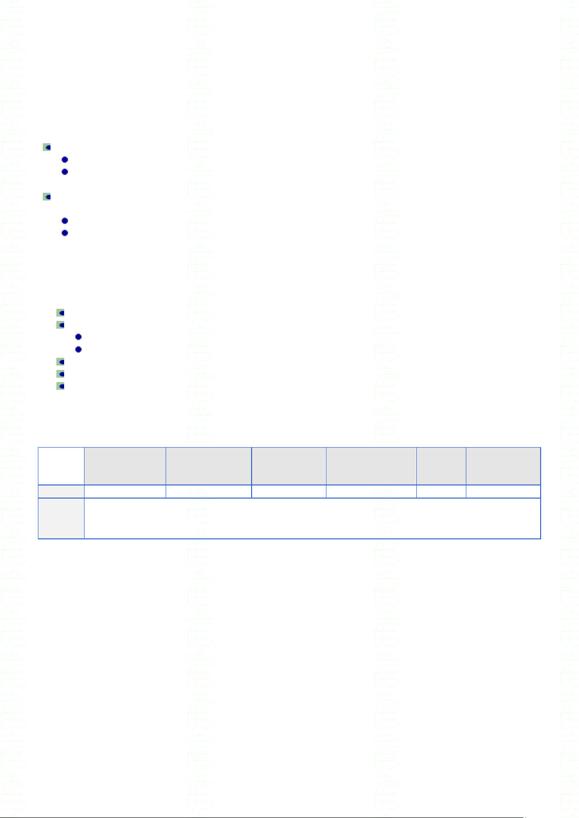
This manual is written for the following XS
series models:
According to your unit model, please refer to the corresponding section in the following pages.
XS user manual v0.55 - 1 -

XS series operating manual
WARRANTY
SEFELEC warrants that units are free from defects in material and
workmanship. SEFELEC warrants also that, when properly used, that units
will perform in accordance with specifications of this manual.
If within one year after original delivery it is found not to meet this standard,
it will be repaired at no charge in SEFELEC service facility in Lognes.
Changes in the unit not approved by SEFELEC will cancel this warranty.
SEFELEC will not be liable for any indirect damages resulting of the use of
the unit.
This warranty is in lieu of all other warranties.
XS user manual v0.55 - 2 -

XS series operating manual
Restrictions due to the accessories or the
options
Ground continuity measurement
CO184/3 to CO184/10 : Maximum current regulation 10A for 6V, 20A for 12V.
CO183/3 to CO183/10 : Maximum current regulation 10A for 6V, 20A for 12V.
TE66/3 to TE66/10 : Maximum current regulation 10A for 6V, 20A for 12V.
TE80/3 to TE80/10 : Maximum current regulation 10A for 6V, 20A for 12V.
TE81/3 to TE81/10 : Maximum current regulation 10A for 6V, 20A for 12V.
CS1 : Maximum current regulation 10A for 6V, 20A for 12V.
Hipot test
CO193 CO174, CO185,CO192 : 4000VAC limited max. voltage.
CO200 to CO209 : 4000VAC limited max. voltage.
FMG501 : 4200VAC limited max. voltage.
Insulation measurement
CO 210 : Measurement limited to 2GΩ
FMG501 rack and Option MG-55 or MG-57(three phase) : Measurement limited to 2GΩ.
XS user manual v0.55 - 3 -

XS series operating manual
Summary
This manual is written for the following XS series models: .......................................................... 1
WARRANTY ................................................................................................................................ 2
Restrictions due to the accessories or the options ....................................................................... 3
Ground continuity measurement .............................................................................................. 3
Hipot test .................................................................................................................................. 3
Insulation measurement ........................................................................................................... 3
Summary ...................................................................................................................................... 4
Specifications ............................................................................................................................. 10
Power supply .......................................................................................................................... 10
Operating condition ................................................................................................................ 10
Weight and dimensions ................................ ................................ ................................ .......... 10
Over voltage category ............................................................................................................ 10
Pollution rate .......................................................................................................................... 10
Safety class ............................................................................................................................ 10
1 DIELECTRIC STRENGTH TEST 50VA .............................................................................. 11
(hipot 50VA test) ........................................................................................................................ 11
Output voltage ........................................................................................................................ 11
Voltage reading ...................................................................................................................... 11
Short circuit current ................................................................................................................ 11
Breakdown detection .............................................................................................................. 11
Current variation mode: I ................................................................................................. 11
Maximum current limit : IMAX ............................................................................................. 12
Fast maximum current limit : F(ast)IMAX ............................................................................ 12
Fast maximum current and variation current limit : FIMAX + I .......................................... 12
Maximum current and variation current limit : IMAX + I .................................................... 12
Minimum current limit : IMIN ............................................................................................... 12
Without detection ................................................................................................................ 12
Permanent current measurement ........................................................................................... 13
Fault indication ....................................................................................................................... 13
Timer ................................................................................................ ................................ ...... 13
(mode) MANUAL................................................................................................................. 13
(mode) DEFAULT ............................................................................................................... 13
(mode) AUTO ..................................................................................................................... 13
1 µA current resolution (OPTION 116-00) .............................................................................. 14
Value display ...................................................................................................................... 14
Threshold set up ................................................................................................................. 14
Current measure ................................................................................................................. 14
(hipot 500VA test) ...................................................................................................................... 15
Output voltage ........................................................................................................................ 15
Voltage reading ...................................................................................................................... 15
Short circuit current ................................................................................................................ 15
Breakdown detection .............................................................................................................. 15
Current variation mode : I ................................................................................................ 15
Maximum current limit : IMAX ............................................................................................. 16
Fast maximum current limit : F(ast)IMAX ............................................................................ 16
Fast maximum current and variation current limit : FIMAX + I .......................................... 16
XS user manual v0.55 - 4 -

XS series operating manual
Maximum current and variation current limit : IMAX + I .................................................... 16
Minimum current limit : IMIN ............................................................................................... 16
Without detection ................................................................................................................ 16
Permanent current measurement ........................................................................................... 17
Fault indication ....................................................................................................................... 17
Timer ................................................................................................ ................................ ...... 17
(mode) MANUAL................................................................................................................. 17
(mode) DEFAULT ............................................................................................................... 17
(mode) AUTO ..................................................................................................................... 17
2 DIELECTRIC STRENGTH TEST 10VA .............................................................................. 18
Output voltage ........................................................................................................................ 18
Voltage reading ...................................................................................................................... 18
Short circuit current ................................................................................................................ 18
Breakdown detection .............................................................................................................. 18
Current variation mode : I ................................................................................................ 18
Maximum current limit : IMAX ............................................................................................. 19
Fast maximum current limit : F(ast)IMAX ............................................................................ 19
Fast maximum current and variation current limit : FIMAX + I .......................................... 19
Maximum current and variation current limit : IMAX + I .................................................... 19
Minimum current limit : IMIN ............................................................................................... 19
Without detection ................................................................................................................ 19
Permanent current measurement ........................................................................................... 20
Fault indication ....................................................................................................................... 20
Timer ................................................................................................ ................................ ...... 20
(mode) MANUAL................................................................................................................. 20
(mode) DEFAULT ............................................................................................................... 20
(mode) AUTO ..................................................................................................................... 20
Detection of capacitive samples ............................................................................................. 21
3 Megohmmeter function (insulation resistance measurement) ............................................. 22
500V megohmmeter function ................................................................................................. 22
Measurement voltage ......................................................................................................... 22
Measurement range ............................................................................................................ 22
Measurement accuracy ....................................................................................................... 22
Measurement threshold ...................................................................................................... 23
Timer ................................................................................................................................... 23
1000V megohmmeter function (option XS26 or MXS1000) .................................................... 24
Measurement voltage ......................................................................................................... 24
Measurement range ............................................................................................................ 24
Measurement accuracy ....................................................................................................... 24
Measurement threshold ...................................................................................................... 25
Timer ................................................................................................................................... 25
1500V megohmmeter function (SXS16) ................................................................................. 25
Measurement voltage ......................................................................................................... 25
Measurement range ............................................................................................................ 25
Measurement accuracy ....................................................................................................... 26
Measurement threshold ...................................................................................................... 26
Timer ................................................................................................................................... 27
4 Ground continuity function .................................................................................................. 28
Measurement current .......................................................................................................... 28
Open circuit voltage ................................................................................................ ............ 28
XS user manual v0.55 - 5 -

XS series operating manual
Measurement accuracy ....................................................................................................... 28
Measurement thresholds .................................................................................................... 29
Timer ................................................................................................................................... 29
Measurement cycles ........................................................................................................... 29
5 introduction - operating instruction ...................................................................................... 30
MEANING OF THE DIFFERENT SYMBOLS ON THE INSTRUMENT .................................. 30
PRODUCT OVERVIEW ......................................................................................................... 31
Front panel description ........................................................................................................... 32
Keys definition .................................................................................................................... 32
Liquid Crystal Display (LCD) description ............................................................................. 33
Rear panel description............................................................................................................ 34
Supplied accessories.............................................................................................................. 34
Available accessories and options ......................................................................................... 35
Installation .............................................................................................................................. 37
Preliminary instructions ....................................................................................................... 37
Power ON ............................................................................................................................... 38
Operator safety advices .......................................................................................................... 38
Connection to a specimen ...................................................................................................... 39
Connection for the insulation resistance measurement and dielectric strength test (any
model) ................................................................................................................................. 39
6 Unit configuration ................................................................................................................ 41
Language selection ................................................................................................................ 41
Beep on FAIL configuration .................................................................................................... 42
Filtering configuration for capacitive specimen ....................................................................... 42
(mode) CAPACITOR ........................................................................................................... 42
(mode) R.H.TIME ( Real Hold Time ) .................................................................................. 42
(mode) NORMAL ................................................................................................................ 42
Access control to the parameters ........................................................................................... 43
(access) UNLOCKED ......................................................................................................... 43
(access) READ ONLY ......................................................................................................... 43
(access) LOCKED............................................................................................................... 43
Password programming .......................................................................................................... 43
Measurement display ............................................................................................................. 45
Remote trigger mode .............................................................................................................. 46
Electrical connection and trigger ......................................................................................... 46
Interface selection .................................................................................................................. 47
Sequence selection (Option 04) ............................................................................................. 47
EXPERT mode Activation ....................................................................................................... 48
7 Insulation resistance measurement .................................................................................... 49
Parameter setting ................................................................................................................... 49
Measurement threshold selection ....................................................................................... 50
Timer operation ................................................................................................................... 51
Parameter memorization ..................................................................................................... 53
Insulation resistance measurement ........................................................................................ 54
Error messages ...................................................................................................................... 55
8 Dielectric strength test (hipot test)....................................................................................... 56
Setting ................................ ................................................................ ................................ .... 56
Test voltage selection ......................................................................................................... 57
Test voltage application on the specimen ........................................................................... 58
To set the HOLD time ......................................................................................................... 58
XS user manual v0.55 - 6 -

XS series operating manual
To set the RISE and FALL times ........................................................................................ 59
Breakdown detection mode selection ................................................................................. 60
Current variation mode : I ................................................................................................ 60
Maximum current limit : IMAX ............................................................................................. 60
Fast maximum current limit : F(ast)IMAX ............................................................................ 60
Fast maximum current and variation current limit : FIMAX + I .......................................... 60
Maximum current and variation current limit : IMAX + I .................................................... 61
Without detection ................................................................................................................ 61
Minimum current limit : IMIN ............................................................................................... 61
IMIN and IMAX threshold adjustment ................................................................................. 62
Delta I level adjustment ....................................................................................................... 63
Timer operation ................................................................................................................... 64
Activation of the capacitive sample detection ..................................................................... 65
Parameter memorization ..................................................................................................... 65
Expert mode parameters only ................................................................................................ 66
Breakdown detection mode selection during the ramps...................................................... 66
IMAX and delta I thresholds adjustment during the ramps .................................................. 67
Control of the display during the ramps .............................................................................. 67
Power mode for 60335 and 60204 standards ..................................................................... 67
Configuration of the minimum capacity value to detect ....................................................... 68
Dielectric strength test ( Hipot test) ........................................................................................ 68
Dielectric strength test error messages .................................................................................. 71
9 Ground continuity resistance measurement ........................................................................ 72
Setting ................................ ................................................................ ................................ .... 72
Measurement current selection ........................................................................................... 73
Open circuit test voltage selection (6 or 12 VAC) ............................................................... 73
Resistance threshold selection ........................................................................................... 74
Timer operation ................................................................................................................... 75
Parameter memorization ..................................................................................................... 77
Ground continuity resistance measurement ........................................................................... 78
Ground continuity measurement error messages ................................................................... 79
10 Sequence mode operation (SXS) .................................................................................... 80
Measurement function setting ................................................................................................ 80
Sequence setting .................................................................................................................... 80
Parameter memorization ..................................................................................................... 81
Function selection ............................................................................................................... 82
Parameter memory number selection ................................................................................. 83
Series of tests with manual control ......................................................................................... 83
How to run a simple sequence ............................................................................................... 84
Sequence with manual control ............................................................................................... 85
Multiple ground continuity ................................ ................................ ................................ ....... 85
Multiple ground continuity operation ....................................................................................... 86
Multiple ground continuity followed by a dielectric strength test ( automatic sequence) ......... 87
Error messages for the Sequence mode ................................................................................ 88
11 Accessories with remote control feature .......................................................................... 89
Accessories type .................................................................................................................... 89
Connection ............................................................................................................................. 89
Operation ............................................................................................................................ 90
Specific case for the sequence (SXS50 & 500) .................................................................. 91
12 Input output Interfaces ..................................................................................................... 92
XS user manual v0.55 - 7 -

XS series operating manual
Input-Output for Programmable Logic Controller Interface (PLC) ........................................... 92
Electrical specifications ....................................................................................................... 92
Description of the logical states .......................................................................................... 92
Connections ........................................................................................................................ 93
Description of the input output signals ................................ ................................ ................ 94
Measurement discharge cycle ............................................................................................ 95
Information on cycle timing ................................................................................................. 96
PLC > RS Interface (Option 115-00) ................................................................................... 101
0 -10 Volts analog input output (03 OPTION ) ...................................................................... 103
Specification ..................................................................................................................... 103
Board setup according to the unit models ......................................................................... 103
Change of the board setup ............................................................................................... 105
Operation .......................................................................................................................... 105
Megohmmeter mode, 2 outputs setup .............................................................................. 106
Megohmmeter mode, 1 output setup ................................................................................ 106
Dielectric strength test mode, 2 outputs setup .................................................................. 107
Dielectric strength test mode, 1 output + 1 input setup ..................................................... 107
Operating instructions ....................................................................................................... 108
IEEE-488 interface ............................................................................................................... 109
Syntax rules ...................................................................................................................... 109
IEEE-488-1 Fonctions availables ...................................................................................... 109
List of the IEEE-488 commands ....................................................................................... 109
Commands ....................................................................................................................... 110
ETHERNET Interface ................................................................................................ ........... 111
Connexion examples ........................................................................................................ 111
How to set the Ethernet interface card under Windows XP .................................................. 112
Procedure ......................................................................................................................... 112
Configuring the connexion on the unit .................................................................................. 114
Protocol and communication port ..................................................................................... 116
Syntax rules ...................................................................................................................... 116
List of the ETHERNET commands.................................................................................... 117
Error message(s) .............................................................................................................. 118
Anomaly ............................................................................................................................ 118
RS232C interface ................................................................................................................. 119
Syntax rules ...................................................................................................................... 120
List of the RS232C commands ......................................................................................... 121
Advices and programming examples ................................................................................ 130
Trouble shooting the RS232 interface............................................................................... 131
13 APPLICATION NOTES ................................................................................................. 132
Why dielectric tests ?............................................................................................................ 132
Glossary of terms ................................................................................................................. 132
Environmental influences ..................................................................................................... 133
Insulation resistance measurement ...................................................................................... 133
Precautions to be observed .............................................................................................. 134
Measurements of capacitors ............................................................................................. 134
Measurements on cables .................................................................................................. 135
Measurement voltage selection ........................................................................................ 135
Dielectric strength tests ........................................................................................................ 136
Selection of the test voltage .............................................................................................. 136
Breakdown detection mode selection ............................................................................... 137
XS user manual v0.55 - 8 -

XS series operating manual
Ground continuity measurement .......................................................................................... 138
Current selection ............................................................................................................... 138
Voltage selection .............................................................................................................. 138
Test time ........................................................................................................................... 138
Precautions to be observed .............................................................................................. 139
14 Safety interlock connector (C5) ..................................................................................... 140
15 Measurement I/O on the rear panel............................................................................... 141
16 Maintenance and calibration ......................................................................................... 142
PRELIMINARY ..................................................................................................................... 142
INSTRUMENT RETURN ...................................................................................................... 142
MAINTENANCE ................................................................................................................... 142
CLEANING ........................................................................................................................... 143
CALIBRATION ..................................................................................................................... 143
17 Annexes ........................................................................................................................ 144
4 wires option for XS series and hipot function ........................................................................ 145
Application ............................................................................................................................ 145
Content of the option ............................................................................................................ 145
Accessory set in the XS-108 option .................................................................................. 145
Accessory set in the XS-109 option .................................................................................. 145
Operation of the XS 4-wire option in XS hipot function ......................................................... 146
Option operation phase ..................................................................................................... 146
Schematic diagram of the option ...................................................................................... 147
Uses cases ....................................................................................................................... 148
HV sensor connection recommendations ......................................................................... 150
Rear view of the unit and accessory connections ................................................................. 152
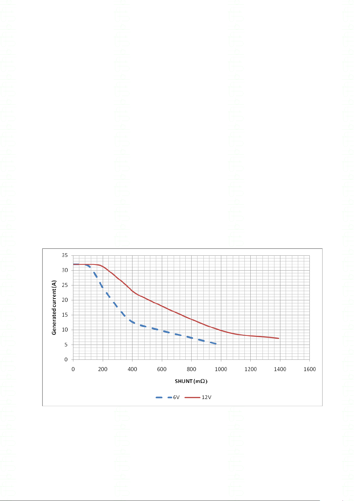
Nominal DC currents in the hipot function ................................................................................ 153
Definition of the nominal DC current ..................................................................................... 153
XS 50VA DC current curves (RXS56, DXS56, SXS56) ........................................................ 153
XS 500VA DC current curves (RXS506, DXS506, SXS506) ................................................ 154
XS user manual v0.55 - 9 -
XS series operating manual
RXS50/56
DXS50/56
RXS500/506
DXS500/506
SXS50/56*
SXS500/506*
SXS16
MXS500/1000
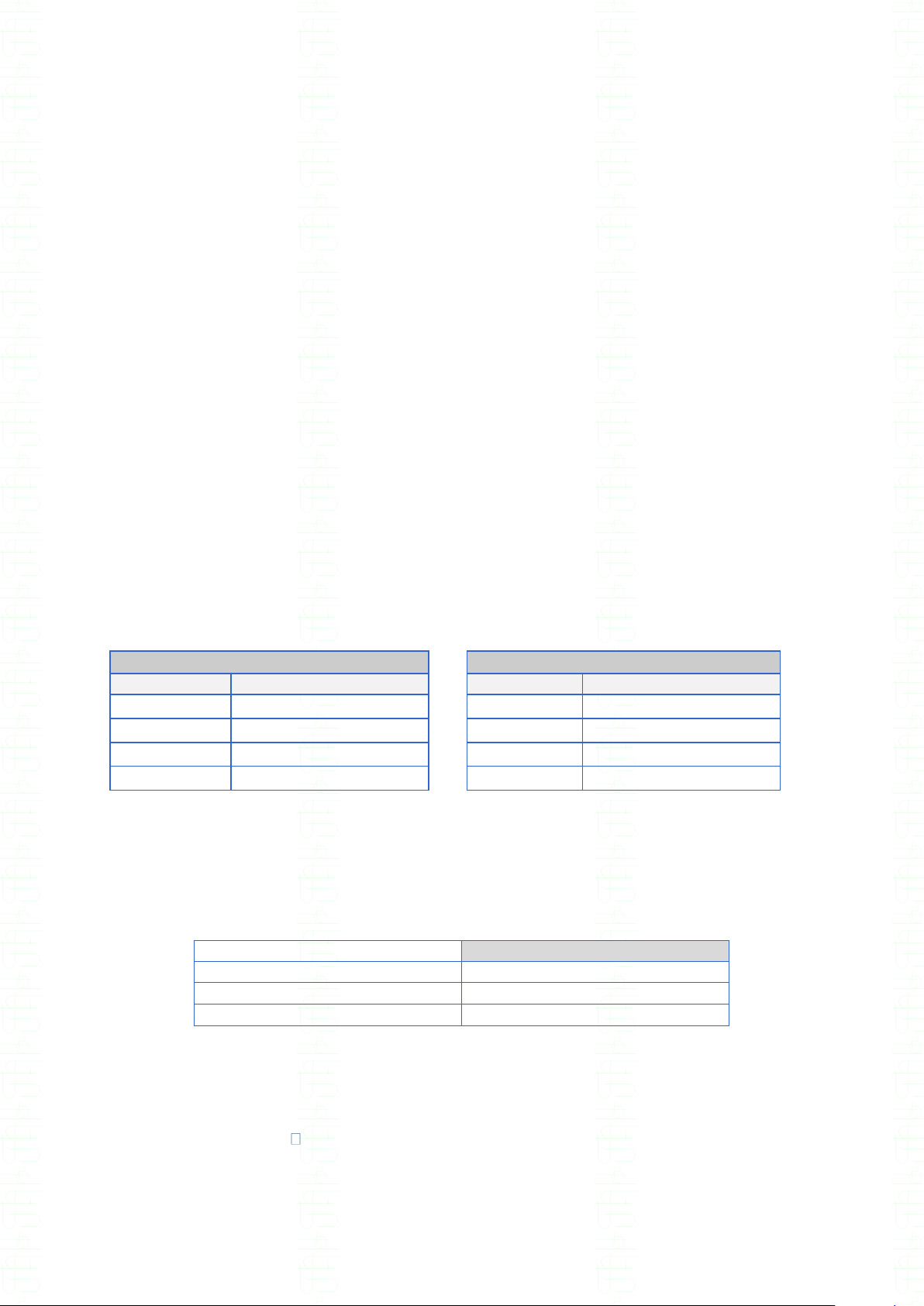
weight
15kg
21kg
27kg
28kg
19Kg
12Kg
height
width
depth
131 mm ± 0.5
440.5 mm ± 0.5
450.5 mm. ± 0.5
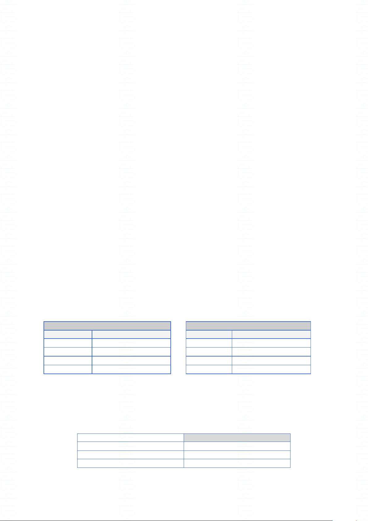
Specifications
Power supply
Mains :
115/230V~ ±15% single phase 47 to 64 Hz (DXS50/56, RXS50/56, SXS50/56, MXS500/1000).
230V~ ±15% single phase 47 to 64 Hz (DXS500/506, RXS500/506, SXS500/506).
Temporized protective fuse in mains socket on the rear panel :
RXS50/56, DXS50/56, SXS50/56, SXS16, MXS500/1000: 2AT for 230V and 4AT for 115V.
RXS500/506, DXS500/506, SXS500/506: 4AT for 230V.
Power consumption: 40VA without load, 550 VA maximum.
Operating condition
The instrument must be used indoor, in horizontal position or on tripode
Operating temperature :
Storage : -10°C to +60°C.
Operation : 0°C to +45°C.
Accuracy is rated after half an hour of warm up and for a relative humidity < 50%.
Altitude : up to 2000 meters
Max. Humidity rate: 80% for a temperature of 31°C.
Weight and dimensions
* Note: the weight of those units being over 18kg, 2 persons are necessary for manipulations.
Over voltage category
CAT II.
Pollution rate
Pollution 2 : Occasional conductive pollution only by condensation.
Safety class
Class I instrument : Earth protection by mains connection.
XS user manual v0.55 - 10 -

XS series operating manual
1 DIELECTRIC STRENGTH TEST 50VA
(hipot 50VA test)
XS50 / XS56 (5kVAC / 6kVDC)
Output voltage
Alternative 50 or 60Hz ( DC voltage on XS56 model).
From 100V to 5 kVAC in one range (100V to 6 KVDC).
Stability < 1% for V mains of 10%.
Positive pole to earth with DC voltage
Ripple < 1% for Is=100 µA with DC voltage
Accuracy of the output voltage: (2%+50volts) in relation with the set value for voltages
between 100 and 5000 volts (6000 volts for DC) and for a current < 100 µA in the fault detection
modes : I, IMAX or I+IMAX.
Discharge of the tested specimen and of the internal capacitor through a 1.5 M resistance with
DC voltage
Voltage reading
By kilovoltmeter directly connected to the output terminals.
Accuracy : (1.5%+20 volts) of the read value.
Display by 600 points digital indicator.
Short circuit current
<15 mA in AC for the maximum voltage adjustment.
<15 mA in DC for the maximum voltage adjustment.
Breakdown detection
Current variation mode: I
The TEST detector automatically carries out the subtraction between the current which flows
normally in the device under test (I=U/Z) and the one which occurs at the time of a fault (I'=I+Ifault).
Amplitude adjustable between : 1 mA and 10mA 10% by 1 mA step.
Width of current pulse : 10µS 20%
XS user manual v0.55 - 11 -

XS series operating manual
Maximum current limit : IMAX
Adjustable from 0.01 mA to 9.99 mA by 0.01mA step.
The unit monitors permanently the current flowing through the sample under test and compares
according the 2 following possibilities:
The high limit ( IMAX) > 0 , the low limit (IMIN) is set to 0
If the measured current is > or = to the IMAX, then the test is FAIL ( breakdown)
The high limit ( IMAX) > 0 , the low limit (IMIN) is set to a value < IMAX
If the measured current is < IMAX and > IMIN then the test is PASS, otherwise the test is
FAIL ( breakdown or I < IMIN)
WARNING :
This detection mode can require between 200 and 300 msec. for the limit detection, and
during this time the current can increase quickly over the limit .
Fast maximum current limit : F(ast)IMAX
Specifications are identical to the IMAX detection mode .
However in the FIMAX mode the breakdown detection is fastest (20 msec.) than in IMAX mode
because the comparison with the current limit is performed directly by electronic circuits and not by
the embedded software.
Accuracy of the detection :
DC: +/- (5%+ 2U)
AC: +/- (10%+2U)
Fast maximum current and variation current limit : FIMAX + I
This mode combines the FIMAX mode and the Delta I mode.
Maximum current and variation current limit : IMAX + I
This mode combines the IMAX mode and the Delta I mode.
Minimum current limit : IMIN
In the above detection modes it is possible to set a minimum value of current flowing through the
specimen under test : IMIN value adjustable from 0.00 mA up to 9.99 mA to insure that the specimen
under test is correctly connected.
Without detection
In this mode there is no current monitoring.
There is no output high voltage adjustment according to the load.
WARNING,
Permanent operation on heavy loads in this mode can heat the electronic amplifier. The
internal fan will start automatically to reduce the temperature, with a possible stop of the HV
generator for safety reasons.
XS user manual v0.55 - 12 -

XS series operating manual
Permanent current measurement
Direct reading of the current on a shunt resistance in the test circuit.
Display of the value on a 999 points digital indicator.
Accuracy : (2.5% + 2 U) of the read value (1U=0.01mA).
In VDC accuracy is given for resistance loads > 1 M.
Fault indication
By message on the LCD display, red and green LED, and audible signal (possibility to inhibit).
Memory storage of the breakdown voltage.
Memory storage of the leakage current in IMAX mode.
Cut off of the high voltage at the first zero crossing of the control sinusoidal signal of the HV
transformer, thus without over voltage.
Timer
(mode) MANUAL
The timer is not used during the test . The voltage output is manually controlled by pressing on the
UP/DOWN arrows. The test stops when a breakdown occurs or when pressing on the red push
button on the front panel.
(mode) DEFAULT
The timer is not used during the test . The voltage output is defined in the parameter VOLTAGE line.
The test stops when a breakdown occurs or when pressing on the red push button on the front
panel.
(mode) AUTO
The test is defined by three consecutive times during which the output voltage rises linearly up to the
preset value ( RISE time) , then is hold to the preset value ( HOLD time) and finally bring back to
zero ( FALL time).
The RISE and FALL times can be set from 0 to 1 sec. by 0.1 sec. step and from 1 to 999 sec. by
1 sec. step.
The HOLD time can be set from 1 to 999sec. by 1 sec. step.
XS user manual v0.55 - 13 -

XS series operating manual
1 µA current resolution (OPTION 116-00)
Add of a new range of current measure between 0 and 999 µA.
Value display
From 0 a 999 µA, display in µA
over 999 µA, display in mA
Threshold set up
With or without the option, the ΔI threshold can be set from 1 mA ±10 % to 10 mA ± 10% by 1 mA
step.
IMAX, IMIN and FIMAX threshold can be set from:
0 to 999 µA by 1µA step
1mA to 9.99mA by 0.01mA step.
Current measure
- In AC :
±(2.5% + 3 U) U = 1µA for measures between 0 and 200µA
±(2% + 2 U) U = 1µA for measures between 200 µA and 1mA
- In DC :
±(2% + 2 U) U = 1µA
Display of the value on a 999 points digital indicator.
In VDC accuracy is given for resistance loads > 1 M.
XS user manual v0.55 - 14 -

XS series operating manual
DIELECTRIC STRENGTH TEST 500VA
(hipot 500VA test)
XS500 / XS506 (5kVAC / 6kVDC)
Output voltage
Alternative 50 or 60Hz ( DC voltage on XS506 model).
From 100V to 5 kVAC in one range (100V to 6 KVDC).
Stability < 3% for V mains of 10%.
Positive pole to earth with DC voltage
Ripple < 1% for Is=100 µA with DC voltage
Accuracy of the output voltage : (3%+50volts) in relation with the set value for voltages
between 100 and 5000 volts (6000 volts for DC) and for a current < 1mA in the fault detection
modes : I, IMAX or I+IMAX.
Discharge of the tested specimen and of the internal capacitor through a 1.5 M resistance with
DC voltage
Voltage reading
By kilovoltmeter directly connected to the output terminals.
Accuracy : (1.5%+20 volts) of the read value.
Display by 600 points digital indicator.
Short circuit current
> 200 mA in AC for the maximum voltage adjustment.
> 100 mA in DC for the maximum voltage adjustment.
Breakdown detection
Current variation mode : I
The TEST detector automatically carries out the subtraction between the current which flows
normally in the device under test (I=U/Z) and the one which occurs at the time of a fault (I'=I+Ifault).
Amplitude adjustable between : 10 mA and 100mA 10% by 10 mA step.
Width of current pulse : 10µS 20%
XS user manual v0.55 - 15 -

XS series operating manual
Maximum current limit : IMAX
Adjustable from 0.1 mA to 110 mA by 0.1mA step.
The unit monitors permanently the current flowing through the sample under test and compares
according the 2 following possibilities :
The high limit ( IMAX) > 0 , the low limit (IMIN) is set to 0
If the measured current is > or = to the IMAX, then the test is FAIL ( breakdown)
The high limit ( IMAX) > 0 , the low limit (IMIN) is set to a value < IMAX
If the measured current is < IMAX and > IMIN then the test is PASS, otherwise the test is
FAIL ( breakdown or I < IMIN)
WARNING :
This detection mode can require between 200 and 300 msec. for the limit detection, and
during this time the current can increase quickly over the limit .
Fast maximum current limit : F(ast)IMAX
Specifications are identical to the IMAX detection mode .
However in the FIMAX mode the breakdown detection is fastest (20 msec.) than in IMAX mode
because the comparison with the current limit is performed directly by electronic circuits and not by
the embedded software.
Accuracy of the detection :
DC: +/- (5%+ 2U)
AC: +/- (10%+2U)
Fast maximum current and variation current limit : FIMAX + I
This mode combines the FIMAX mode and the Delta I mode.
Maximum current and variation current limit : IMAX + I
This mode combines the IMAX mode and the Delta I mode.
Minimum current limit : IMIN
In the above detection modes it is possible to set a minimum value of current flowing through the
specimen under test : IMIN value adjustable from 0.0 mA up to 109 mA to insure that the specimen
under test is correctly connected.
Without detection
In this mode there is no current monitoring.
There is no output high voltage adjustement according to the load.
WARNING,
Permanent operation on heavy loads in this mode can heat the electronic amplifier. The
internal fan will start automaticaly to reduce the temperature, with a possible stop of the HV
generator for safety reasons.
XS user manual v0.55 - 16 -

XS series operating manual
2
dc
2
ac I + I
Permanent current measurement
Direct reading of the current on a shunt resistance in the test circuit.
Display of the value on a 999 points digital indicator.
Accuracy : (2.5% + 2 U) of the read value (1U=0.1mA).
In VDC accuracy is given for resistance loads > 1 M.
Display of « STRONG CURRENT » message as well as « ---MA » when the current is over
110mA (AC current) and 20mA in DC
The current indicated on the display in DC is the rms current. That is to say
Iaff =
Fault indication
By message on the LCD display, red and green LED, and audible signal (possibility to inhibit).
Memory storage of the breakdown voltage.
Memory storage of the leakage current in IMAX mode.
Cut off of the high voltage at the first zero crossing of the control sinusoidal signal of the HV
transformer, thus without over voltage.
Timer
(mode) MANUAL
The timer is not used during the test . The voltage output is manually controlled by pressing on the
UP/DOWN arrows. The test stops when a breakdown occurs or when pressing on the red push
button on the front panel.
(mode) DEFAULT
The timer is not used during the test . The voltage output is defined in the parameter VOLTAGE line.
The test stops when a breakdown occurs or when pressing on the red push button on the front
panel.
(mode) AUTO
The test is defined by three consecutive times during which the output voltage rises linearly up to the
preset value ( RISE time) , then is hold to the preset value ( HOLD time) and finally bring back to
zero ( FALL time).
The RISE and FALL times can be set from 0 to 1 sec. by 0.1 sec. step and from 1 to 999 sec. by 1
sec. step.
The HOLD time can be set from 1 to 999sec. by 1 sec. step.
XS user manual v0.55 - 17 -

XS series operating manual
2 DIELECTRIC STRENGTH TEST 10VA
XS16 (10kVDC)
Output voltage
Continuous voltages only
From 100VDC to 10kVDC in one range.
Stability < 3% for V mains of 10%.
Negative pole to earth with DC voltage
Ripple < 0.1% for Is ≤ 1 mA
Accuracy of the output voltage : (2%+20volts) in relation with the set value for voltages
between 100 and 10000 volts and for a current < 100µA.
Discharge of the tested specimen and of the internal capacitor through a 1.5 M resistance
Voltage reading
By kilovoltmeter directly connected to the output terminals.
Accuracy : (1%+10 volts) of the read value.
Display by 2000 points digital indicator.
Short circuit current
≤ 1 mA for voltages between 100V and 10kVDC.
Breakdown detection
Current variation mode : I
The TEST detector automatically carries out the subtraction between the current which flows
normally in the device under test (I=U/Z) and the one which occurs at the time of a fault (I'=I+Ifault).
Amplitude fixed to 1 mA 10%.
Width of current pulse : 10µS 20%
XS user manual v0.55 - 18 -

XS series operating manual
Maximum current limit : IMAX
Adjustable from 0.1 µA to 100.0 µA by 0.1µA step, and from 100µA to 1000µA by 1µA step.
The unit monitors permanently the current flowing through the sample under test and compares
according the 2 following possibilities :
The high limit ( IMAX) > 0 , the low limit (IMIN) is set to 0
If the measured current is > or = to the IMAX, then the test is FAIL ( breakdown)
The high limit ( IMAX) > 0 , the low limit (IMIN) is set to a value < IMAX
If the measured current is < IMAX and > IMIN then the test is PASS, otherwise the test is
FAIL ( breakdown or I < IMIN)
WARNING :
This detection mode can require between 200 and 300 msec. for the limit detection, and
during this time the current can increase quickly over the limit .
Fast maximum current limit : F(ast)IMAX
Specifications are identical to the IMAX detection mode .
However in the FIMAX mode the breakdown detection is fastest (20 msec.) than in IMAX mode
because the comparison with the current limit is performed directly by electronic circuits and not by
the embedded software.
Accuracy of the detection :
For a threshold between 0.1µA and 100.0µA : +/- (5%+ 1µA)
For a threshold between 100µA and 1000µA : +/- (5%+ 5µA)
Fast maximum current and variation current limit : FIMAX + I
This mode combines the FIMAX mode and the Delta I mode.
Maximum current and variation current limit : IMAX + I
This mode combines the IMAX mode and the Delta I mode.
Minimum current limit : IMIN
In the above detection modes it is possible to set a minimum value of current flowing through the
specimen under test : IMIN value adjustable from 0.0 µA up to 1000 µA to insure that the specimen
under test is correctly connected.
Without detection
In this mode there is no current monitoring.
XS user manual v0.55 - 19 -

XS series operating manual
Permanent current measurement
Reading of the current thanks to shunt resistances in the test circuit.
The current is read according to two ranges (one shunt resistance for each range):
- G1 : from 0.0µA up to 100.0µA
- G2: from 100µA up to 1000µA
Display of the value on a 1000 points digital indicator.
The accuracy is the following :
- (1% + 0.2µA) in the G1 range
- (1% + 2µA) in the G2 range
Fault indication
By message on the LCD display, red and green LED, and audible signal (possibility to inhibit).
Memory storage of the breakdown voltage.
Memory storage of the leakage current in IMAX mode.
Cut off of the high voltage without over voltage.
Timer
(mode) MANUAL
The timer is not used during the test . The voltage output is manually controlled by pressing on the
UP/DOWN arrows. The test stops when a breakdown occurs or when pressing on the red push
button on the front panel.
(mode) DEFAULT
The timer is not used during the test. The voltage output is defined in the parameter VOLTAGE line.
The test stops when a breakdown occurs or when pressing on the red push button on the front
panel.
(mode) AUTO
The test is defined by three consecutive times during which the output voltage rises linearly up to the
preset value ( RISE time) , then is hold to the preset value ( HOLD time) and finally bring back to
zero ( FALL time).
The RISE time can be set in seconds, from 2 to 60 sec. by 1 sec. step, or can be set in V/s.
The FALL time can be set in seconds, from 0 to 60 sec. by 1 sec. step, or can be set in V/s.
In the case of ramps set in V/s, the value translated into seconds must stay between the time limits
given above. For example, if the test voltage is 5000VDC and the ramp up set by the user is
5000V/s, this value will not be accepted because it is equivalent to a ramp up time of 1s < 2s,
whereas if the value of the ramp up is 2400V/s, it will be accepted.
The HOLD time can be set from 1 to 999sec. by 1 sec. step.
XS user manual v0.55 - 20 -

XS series operating manual
Detection of capacitive samples
Before starting a test, it is possible to detect whether the sample is properly connected to the unit or not.
This is possible provided that the sample to test has a capacitive value of at least 10nF. If the detection
is activated, a pulse of 100V magnitude and of 1s duration is generated, right before the hipot test starts.
The capacity value is deduced from the current measured during this pulse. If the capacity value
deduced is high enough, the sample is considered detected and the test continues. Otherwise, the test is
stopped, and the hipot voltage is not generated.
By default, the detection threshold is set to 10nF. When the EXPERT mode is activated, it is possible to
configure this detection threshold between 5nF and 10nF by 1nF steps and between 10nF and 1000nF
by 10nF steps.
Precision on the detection threshold : ±40%
Ex: To detect samples of at least 10nF capacitive value, a threshold of at least 10nF(1-40%)=5nF should
be set to ensure that the absence/presence of the sample will be detected every time. Likewise, a
detection threshold of 10nF ensures the detection of absence/presence of samples with capacitive
values of at least 10nF/(60%) = 17nF.
XS user manual v0.55 - 21 -
XS series operating manual
200G basic version
2T option version
Voltage
Measurement range
Voltage
Measurement range
50V
50k to 20G
50V
50k to 200G
100V
100k to 40G
100V
100k to 400G
250V
250k to 100G
250V
250k to 1T
500V
500k to 200G
500V
500k to 2T
DXS and SXS models
200 G basic version
(1.5% + 1U)
2 T option and U<=200VDC
(2% + 1U)
2 T option and U > 200VDC
(1% x Utest / 100 + 1U)
3 Megohmmeter function (insulation resistance
measurement)
500V megohmmeter function
(MXS500,DXS50/56,DXS500/506,SXS50/56,SXS500/506)
Measurement voltage
Voltage adjustable from 10V to 500VDC by 1 volt step.
Accuracy : ±(1% + 1V).
Positive pole of the HV generator is grounded ( earth)
Dynamic stability for a mains V = ±10% : >1%.
The maximum current in the measurement circuit is : 2 mA ±20%.
The discharge current is limited by a 2.2 k resistor.
Measurement range
Display : 2000 digits
The measurement range is defined by the following formula :
(Utest / Umax generator ) x 200 G*
* or 2T according to the option
This gives the following board for the 50,100, 250, 500VDC standard voltages
Measurement accuracy
2000 digits numeric display with unity indication (K, M, G,T).
Accuracy (% of the reading, 1U = 1 digit ) :
XS user manual v0.55 - 22 -

XS series operating manual
LOW
THRESHOLD
MEASURED
value
HIGH
THRESHOLD
Result
10 M
15.4 M
200 G*
PASS ( insulation > LOW limit )
10 M
9.0 M
100 M
FAIL ( insulation < LOW limit)
55 M
63.2 M
80 M
PASS ( insulation > LOW limit + < HIGH limit)
45 M
110 G
75 M
FAIL (insulation > HIGH limit )
CAPACITANCE mode : from 1.00M to 200G (or 2 T for option 20) with an accuracy equal to the
NORMAL mode accuracy ±100k
Input impedance = 10 M ±1%
Measurement threshold
The megohmmeter function can operate either with one or two measurement threshold(s) between
50k up to 200G (2T with option 20 ).
A measurement is PASS after comparison between the displayed value and the thresholds.
When looking for a value only higher than a limit, the LOW THRESHOLD is used to set the limit and
the HIGH THRESHOLD is not used by setting a value equal to the maximum resistance ( basically
200G).
When looking for an insulation resistance higher than a limit but not too much high ( which can
means that the specimen is not correctly connected), then the LOW THRESHOLD is set the
minimum insulation value expected and the HIGH THRESHOLD is set to the maximum insulation
value expected.
Setting examples:
* threshold not active
Timer
The measurement voltage can stay permanently ( timer value set to 0 sec.) or during a time
between 1 and 999 sec. adjustable by 1 sec. step.
Rise and fall times are adjustable in time ( second ) or in voltage increase ( dv/dt) from
0.1 to 0.9 sec. and from 1 to 999 sec. or in V/s from 1V/s to 500V/s.
XS user manual v0.55 - 23 -
XS series operating manual
200G basic version
2T option version
Voltage
Measurement range
Voltage
Measurement range
100V
100k to 20G
100V
100k to 200G
250V
250k to 50G
250V
250k to 500G
500V
500k to 100G
500V
500k to 1T
1000V
1M to 200G
1000V
to 2T
DXS and SXS models
200 G basic version
(1.5% + 1U)
2 T option and U<=200VDC
(2% + 1U)
2 T option and U > 200VDC
(1% x Utest / 100 + 1U)
1000V megohmmeter function (option XS26 or MXS1000)
Measurement voltage
Voltage adjustable from 20V to 1000VDC by 1 volt step.
Accuracy : ±(1% + 1V).
Positive pole of the HV generator is grounded (earth)
Dynamic stability for a mains ΔV = ±10% : <±1%.
The maximum current in the measurement circuit is : 2 mA ±20%.
The discharge current is limited by a 2.2 k resistor.
Measurement range
Display : 2000 digits
The measurement range is defined by the following formula:
(Utest / Umax generator ) x 200 G *
* or 2T according to the option
This gives the following board for the 100, 250, 500, 1000VDC standard voltages
Measurement accuracy
2000 digits numeric display with unity indication (K, M, G,T).
Accuracy (% of the reading, 1U = 1 digit ) :
CAPACITANCE mode : from 1.00M to 200G (or 2 T for option 20) with an accuracy equal to the
NORMAL mode accuracy ±100k
Input impedance = 10 M ±1%
XS user manual v0.55 - 24 -

XS series operating manual
LOW
THRESHOLD
MEASURED
value
HIGH
THRESHOLD
Result
10 M
15.4 M
200 G*
PASS ( insulation > LOW limit )
10 M
9.0 M
100 M
FAIL ( insulation < LOW limit)
55 M
63.2 M
80 M
PASS ( insulation > LOW limit + < HIGH limit)
45 M
110 G
75 M
FAIL (insulation > HIGH limit )
Measurement threshold
The megohmmeter function can operate either with one or two measurement threshold(s) between
50k up to 200G (2T with option 20 ).
A measurement is PASS after comparison between the displayed value and the thresholds.
When looking for a value only higher than a limit, the LOW THRESHOLD is used to set the limit and
the HIGH THRESHOLD is not used by setting a value equal to the maximum resistance (basically
200G ).
When looking for an insulation resistance higher than a limit but not too much high ( which can
means that the specimen is not correctly connected), then the LOW THRESHOLD is set the
minimum insulation value expected and the HIGH THRESHOLD is set to the maximum insulation
value expected.
Setting examples:
* threshold not active
Timer
The measurement voltage can stay permanently ( timer value set to 0 sec.) or during a time
between 1 and 999 sec. adjustable by 1 sec. step.
Rise and fall times are adjustable in time ( second ) or in voltage increase ( dv/dt) from
0.1 to 0.9sec. and from 1 to 999 sec. or in V/s from 1V/s to 1000V/s.
1500V megohmmeter function (SXS16)
Measurement voltage
Voltage adjustable from 500V to 1500VDC by 10 volt step.
Accuracy : ±(2% + 20V)
Positive pole of the HV generator is grounded (earth)
Dynamic stability for a mains ΔV = ±10% : < 1%.
The maximum current in the measurement circuit is : 1 mA .
The discharge current is limited by a 1.5M resistor.
Measurement range
Display : 2000 digits
XS user manual v0.55 - 25 -

XS series operating manual
Voltage
Measurement range
500V
1M to 6.66G
750V
1M to 10G
1000V
1M to 13.34G
1500V
1.5M to 20G
LOW
THRESHOLD
MEASURED
value
HIGH
THRESHOLD
Result
10 M
15.4 M
20 G*
PASS ( insulation > LOW limit )
10 M
9.0 M
100 M
FAIL ( insulation < LOW limit)
55 M
63.2 M
80 M
PASS ( insulation > LOW limit + < HIGH limit)
45 M
110 G
75 M
FAIL (insulation > HIGH limit )
The measurement range is defined by the following formula:
(Utest / Umax generator) x 20 G
This gives the following board for the 500, 750, 1000 et 1500V standard voltages
Measurement accuracy
2000 digits numeric display with unity indication (K, M, G, T).
Accuracy (% of the reading, 1U = 1 digit) : ±(1% + 1U)
NORMAL mode : from 1.00MΩ to 20GΩ
Input impedance = 10kΩ ± 1%.
CAPACITANCE mode: from 1.00M to 20G with an accuracy equal to the NORMAL mode
accuracy ±100k
Input impedance = 10 M ±1%
Measurement threshold
The megohmmeter function can operate either with one or two measurement threshold(s) between
1M up to 20G.
A measurement is PASS after comparison between the displayed value and the thresholds.
When looking for a value only higher than a limit, the LOW THRESHOLD is used to set the limit and
the HIGH THRESHOLD is not used by setting a value equal to the maximum resistance (basically
20G).
When looking for an insulation resistance higher than a limit but not too much high ( which can
means that the specimen is not correctly connected), then the LOW THRESHOLD is set the
minimum insulation value expected and the HIGH THRESHOLD is set to the maximum insulation
value expected.
Setting examples:
* threshold not active
XS user manual v0.55 - 26 -

XS series operating manual
Timer
The measurement voltage can stay permanently ( timer value set to 0 sec.) or during a time
between 1 and 999 sec. adjustable by 1 sec. step.
Rise time is adjustable in time (seconds), from 2s to 60s by step of 1s, or in voltage increase (V/s).
Fall time is adjustable in time (seconds), from 0 to 60s by step of 1s, or in voltage increase (V/s).
In case ramps are set in V/s, the value translated into seconds must stay within the time limits given
above. For example, if the test voltage is 1000VDC and the ramp up set by the user is 1000V/s, this
value will not be accepted because it is equivalent to a ramp up time of 1s < 2s, whereas if the value
of the ramp up is 450V/s, it will be accepted.
XS user manual v0.55 - 27 -
XS series operating manual
4 Ground continuity function
Measurement current
From 5 to 32A AC ( 40A for CXS 40 ) by step of 0.5 A AC.
Frequency = mains frequency
Accuracy : (1% + 500mA).
Open circuit voltage
< 6 VAC or < 12 VAC.( < 9V for CXS40 )
Sinus wave.
Frequency identical to the mains.
Measurement accuracy
Display on 1500 points digital indicator with unity indications (m).
Accuracy (in % of the reading. 1U = 1 display count 1m) : (2.5%+10U) in the following
measurement range :
XS user manual v0.55 - 28 -

XS series operating manual
LOW limit
Measure
HIGH limit
Test result
0 m
98.0 m
100 m
PASS ( continuity < High limit )
0 m
120 m
100 m
FAIL ( continuity > High limit )
55 m
63.2 m
80 m
PASS ( continuity > Low limit and < High limit)
45 m
10 m
75 m
FAIL ( continuity < Low limit)
Cycle
1/1
1/2
1/3
Operation
time
25 minutes
5 hours
Permanent
Measurement thresholds
The ground continuity function can operate either with one or two measurement threshold(s)
between 1m to 1500m.
A measurement is PASS after comparison between the displayed value and the thresholds.
When looking for a value only lower than a limit, the HIGH THRESHOLD is used to set the limit and
the LOW THRESHOLD is not used by setting a value equal to the minimum resistance ( basically
0m ).
When looking for a ground continuity resistance lower than a limit but not too much low ( which can
means that the specimen is not correctly connected), then the LOW THRESHOLD is set the
minimum continuity value expected and the HIGH THRESHOLD is set to the maximum continuity
value expected.
Setting examples:
* threshold not active
Timer
The measurement voltage can stay permanently ( timer value set to 0 sec.) or during a time
between 1 and 999 sec. adjustable by 1 sec. step.
Rise and fall times are adjustable in time ( second ) or in voltage increase ( dv/dt) from
0.1 to 0.9 sec. and from 1 to 999 sec. or in V/s from 1V/s to 1000V/s.
Measurement cycles
If the current generated is high ( 25A), it can lead to a current overheating of the transformer and
start up its protection (See Section 5.3).
The hereunder board indicates the maximum operating time of the ground continuity resistance
measurement according to the use cycle (1 ½ cycle represents use of the current during one second
for a total duration of the cycle of 2 seconds)
Note : All these duration concern a 32A current. For lower currents, this duration is higher.
XS user manual v0.55 - 29 -
 Loading...