

Eaton MX Frame 15000 RT, MX Frame 20000 RT Installation And User Manual

www.eaton.com
Installation and user
manual
MX Frame
15000 RT
20000 RT
Pulsar Series
34008486EN/AC - Page 3
Introduction
Environmental protection
EATON has implemented an environmental-protection policy.
Products are developed according to an eco-design approach.
Substances
This product does not contain CFCs, HCFCs or asbestos.
Packing
To improve waste treatment and facilitate recycling, separate the various packing components.
◗ The cardboard we use comprises over 50% of recycled cardboard.
◗ Sacks and bags are made of polyethylene.
◗ Packing materials are recyclable and bear the appropriate identification symbol .
Follow all local regulations for the disposal of packing materials.
End of life
EATON will process products at the end of their service life in compliance with local regulations.
EATON works with companies in charge of collecting and eliminating our products at the end of their service life.
◗ Product
The product is made up of recyclable materials.
Dismantling and destruction must take place in compliance with all local regulations concerning waste.
At the end of its service life, the product must be transported to a processing centre for electrical and electronic waste.
◗ Battery
The product contains lead-acid batteries that must be processed according to applicable local regulations concerning
batteries.
The battery may be removed to comply with regulations and in view of correct disposal.
Thank you for selecting an EATON product to protect your electrical equipment.
The MX range has been designed with the utmost care.
We recommended that you take the time to read this manual to take full advantage of the many features of your UPS
(Uninterruptible Power System)
Warning: this is a class A UPS product. In a domestic environment, this product may cause radio interference, in wich
case, the user may be required to take additional measures.
Output cables should not be longer than 10 meters.
If the device must be installed in overvoltage category III or IV envoronments, additional upstream overvoltage
protection must be provided for.
Before installing MX, please read the booklet on the required safety instructions. Then follow the indications in this
manual.
To discover the entire range of EATON products and the options available for the MX range, we invite you to visit
our web site at www.eaton.com or contact your EATON representative.
Material Abbreviation Symbol
number
Polyethylene terephthalate PET 01
High-density polyethylene HDPE 02
Polyvinyl chloride PVC 03
Low-density polyethylene LDPE 04
Polypropylene PP 05
Polystyrene PS 06

34008486EN/AC - Page 4
Introduction
Pictograms
Important instructions that must always be followed.
Information, advice, help.
Visual indication.
Action.
Audio signal.
In the illustrations on the following pages, the symbols below are used:
LED off
LED on

34008486EN/AB - Page 5
Contents
1. Presentation
1.1 Wheels position ............................................................................................................................. 8
1.2 Rack position ................................................................................................................................. 8
1.3 Sub-modules ................................................................................................................................. 8
1.4 Rear panels ....................................................................................................................................9
MX Frame 15000 RT / 20000 RT .................................................................................................. 9
1.5 Display and control panel ........................................................................................................... 10
Sub-module pictograms on display ..............................................................................................10
1.6 Battery extension .........................................................................................................................11
Battery extensions for MX Frame ...............................................................................................11
MX EXB RT (optional battery module) .........................................................................................11
Battery Integration System ..........................................................................................................11
Battery extension cable (1,8 m / 6 ft) ...........................................................................................11
2. Installation
2.1 Unpacking and contents check .................................................................................................. 12
Unpacking ...................................................................................................................................12
Contents check ............................................................................................................................12
2.2 Rack mounting ............................................................................................................................ 13
Wheels removal ...........................................................................................................................13
Rack mounting kit ........................................................................................................................13
UPS module rack mounting .........................................................................................................14
2.3 Mounting sub-modules ..............................................................................................................15
2.4 Communication ports ........................................................................................................... 16
Connection to the RS 232 communication port ...........................................................................16
Connection to the communication port by relays ........................................................................16
Installation of communication card ..............................................................................................17
Remote Power Off communication port ......................................................................................17
2.5 Required protective devices and cable cross-sections ............................................................18
Recommended upstream protection ...........................................................................................18
Recommended downstream protection ......................................................................................18
Required cable cross-sections .....................................................................................................18
2.6 Installation depending on the system earthing arrangement (SEA) .....................................19
Single phase input ........................................................................................................................19
UPS with common Normal and Bypass AC inputs ................................................................19
UPS with separate Normal and Bypass AC inputs ................................................................19
UPS with separate Normal and Bypass AC inputs, supplied by separate sources ............... 20
Frequency converter (without Bypass AC input) .................................................................. 20
Three phases input ..................................................................................................................... 21
UPS with common Normal and Bypass AC inputs ............................................................... 21
UPS with separate Normal and Bypass AC inputs ............................................................... 21
UPS with separate Normal and Bypass AC inputs, supplied by separate sources ............... 22
Frequency converter (without Bypass AC input) .................................................................. 22

34008486EN/AB - Page 6
Contents
2.7 Connections of input/output power cables ..............................................................................23
Input connection ..........................................................................................................................23
Access to terminal block .....................................................................................................23
Single phase input .......................................................................................................................24
Common sources .................................................................................................................24
Separate sources ..................................................................................................................24
Three phases input ......................................................................................................................25
Common sources .................................................................................................................25
Separate sources ..................................................................................................................25
2.8 Fix the terminal block cover .......................................................................................................26
2.9 Extended battery (EXB) connections .........................................................................................27
2.10 Connection of IEC cables to output receptacles .....................................................................27
3. Operation
3.1 Initial start-up ..............................................................................................................................28
3.2 Final start-up sequence ...............................................................................................................28
3.3 Operating modes .........................................................................................................................29
Normal mode .......................................................................................................................29
Battery mode ........................................................................................................................29
3.4 Return on Normal AC source ......................................................................................................29
3.5 UPS shutdown .............................................................................................................................30
4. Access to measurements and personalisation data
4.1 Display organisation ....................................................................................................................31
4.2 Access to measurements ...........................................................................................................31
4.3 Access to UPS set-up and maintenance ....................................................................................31
4.4 UPS set-up ...................................................................................................................................32
Local settings .......................................................................................................................32
Output settings ....................................................................................................................32
ON/OFF settings ..................................................................................................................32
Battery settings ....................................................................................................................33
4.5 Maintenance ................................................................................................................................33
4.6 Personalisation using external software ...................................................................................33
5. Troubleshooting
5.1 Troubleshooting LEDs ................................................................................................................34
5.2 System diagnosis fault ................................................................................................................35
Start with xUPS ...........................................................................................................................35
No start ........................................................................................................................................35
5.3 Environment faults ......................................................................................................................36
5.4 Internal faults ..............................................................................................................................37

34008486EN/AB - Page 7
Contents
6. Life Cycle Monitoring (LCM)
6.1 Description ...................................................................................................................................38
Get free offers ............................................................................................................................. 38
Secure your installation power continuity ................................................................................... 38
Reset or disable LCM ................................................................................................................ 39
7. Maintenance
7.1 Hot swapping the power sub-module ...................................................................................... 40
Disconnecting the power sub-module : .............................................................................. 40
Reconnecting the power sub-module : ............................................................................... 40
7.2 Hot swapping the battery sub-module .................................................................................... 40
Disconnecting the battery sub-module : ............................................................................. 40
Reconnecting the battery sub-module : .............................................................................. 40
7.3 Service position (bypass position) ............................................................................................ 41
7.4 Normal position (online mode) .................................................................................................4 2
7.5 Training centre ............................................................................................................................. 43
8. Appendices
8.1 Technical specifications ..............................................................................................................44
8.2 Glossary .......................................................................................................................................45
34008486EN/AC - Page 8
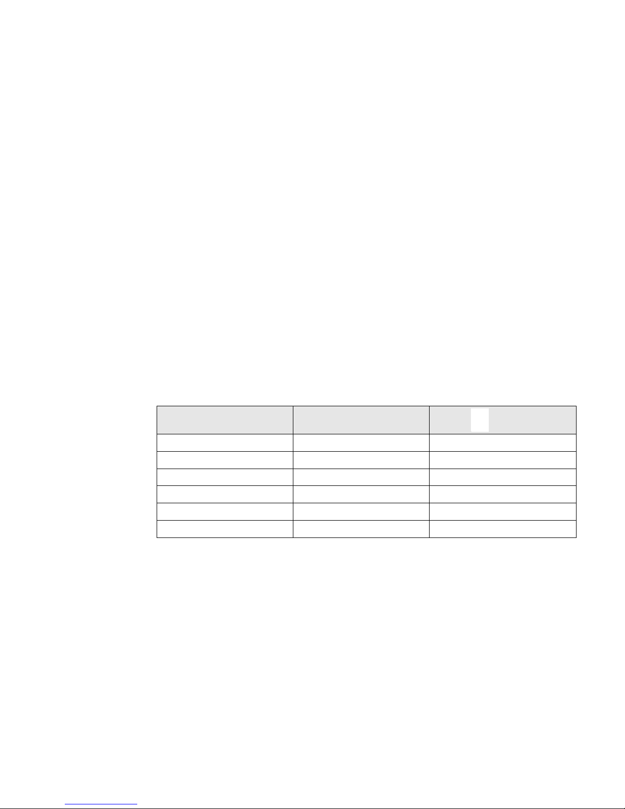
1. Presentation
Wheels position
Rack position
Sub-modules
Dimensions (H x W x D)
MX Frame
15 000 RT/ 20 000 RT
(on wheels)
688x445x738 mm
27 x 18 x 29 inches
Weights
MX Frame 71 kg
157 lbs
MX Frame
15 000 RT
194 kg
428 lbs
MX Frame
20 000 RT
239 kg
527 lbs
Dimensions (H x W x D)
MX Frame
15 000 RT/ 20 000 RT
(wheels removed)
688x445x738 mm
27 x 18 x 29 inches
Weights
MX Frame
Power sub-module
12 kg
26 lbs
MX Frame
Battery sub-module
30 kg
65 lbs
34008486EN/AC - Page 9
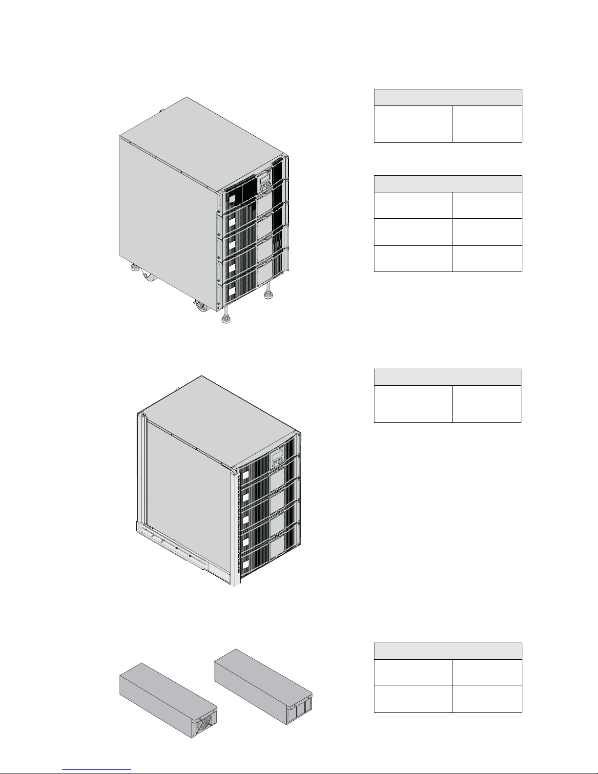
1. Presentation
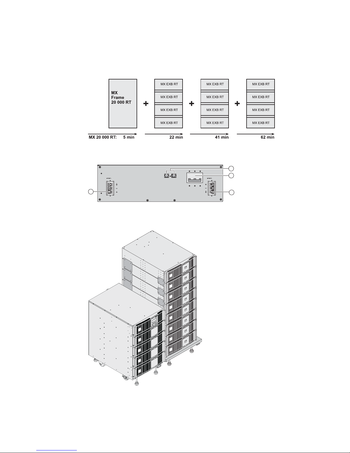
Rear panels
MX Frame 15000 RT / 20000 RT
(1) Normal AC source input switch
(2) Single phase or three-phase input
selection
(3) Residual-current earth-leakage circuit
breaker 30mA for PDU1 and PDU2
(4) Groups of 2 (10A) outlets for
connection of equipment
(5) Groups of 2 (16A) outlets for
connection of equipment
(6) 10A thermal switch
(7) 15A thermal switch
(8) Normal AC source terminal block
(9) Bypass AC source terminal block
(10) Output terminal block
(11) Slot for optional communication card
(12) Manual Bypass switch
(13) Remote Power Off communication
port (RPO).
(14) Communication port by relay
(15) USB communication port
(16) RS232 communication port
(17) Two groups of 2 programmable (10A)
outlets for connection of equipment
(18) Connector for automatic detection of
battery module(s)
(19) Connector for additional battery
module
3
12
18
14
15
16
4
9
8
2
1
11
6
7
5
13
19
17
10
34008486EN/AC - Page 10
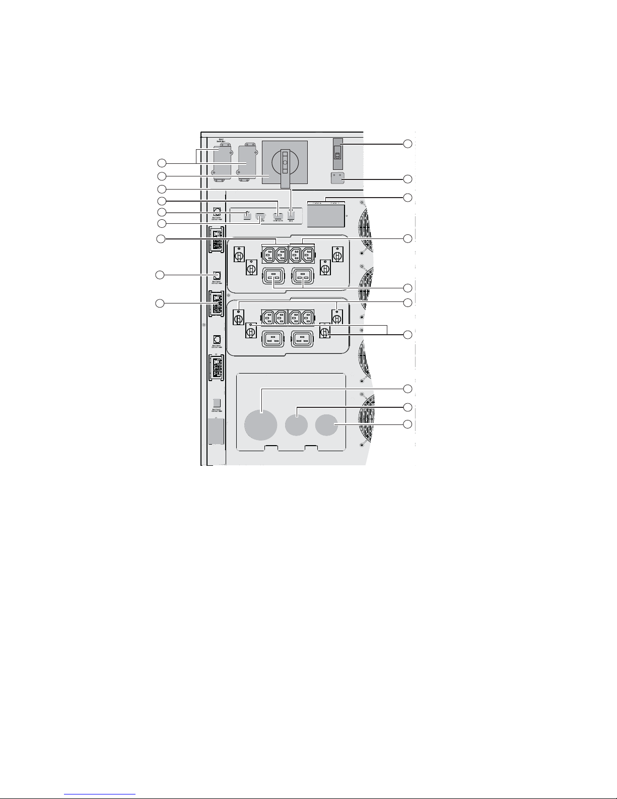
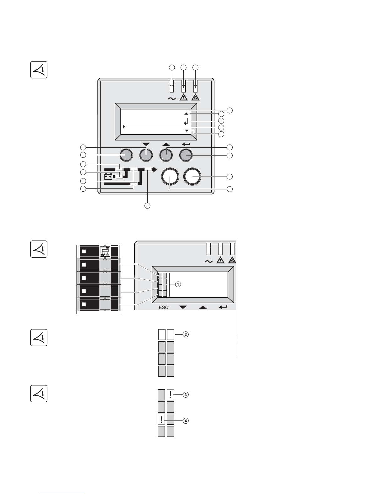
1. Presentation
Display and control panel
Sub-module pictograms on display
(1) Load protected LED
(2) Downgraded operation LED
(3) Load not protected LED
(4) Alphanumeric display
(a) Upper line exists, access by (6)
(b) Lower menu exists, access by (8)
(c) Active line
(d) Lower line exists, access by (5)
(5) (6) Function buttons (scroll down /
scroll up)
(7) Escape (cancel) button
(8) Enter (confirm) button
(9) UPS OFF button
(10) UPS ON button
(11) Rectifier LED
(12) Battery LED
(13) Inverter LED
(14) Bypass LED
(15) Load powered LED
(1) Sub-modules detection
(
(2) The power sub-module and the battery
sub-module are not detected on the level
(MX Frame 15000 RT)
(3) Internal battery sub-module fault
detected
(4) Internal power sub-module fault
detected
For internal sub-module fault description,
see section 5.2, page 35
ESC
IO
7
1 2 3
8
9
10
6
5
11
12
13
14
15
4
a
b
c
d
34008486EN/AC - Page 11
1. Presentation
Battery extension
MX Frame offers a standard backup time of 5 minutes at full load.
To increase backup time up to 62 minutes (at full load), it is possible to connect MX EXB RT modules to the UPSs.
Battery extensions for MX Frame
MX EXB RT (optional battery module)
Battery Integration System
Battery extension cable (1,8 m / 6 ft)
This extended battery cable will be used instead of the standard battery cable when battery modules are distant from
each other (located in two different enclosures, for instance).
(1) Connectors for automatic detection of
battery module(s)
(2) Battery circuit breaker
(3) Connectors for battery modules (to the
UPS or to the other battery modules)
The Battery Integration System is
intended for extended backup time
configurations to conveniently stack and
secure up to 8 modules on the same cart
(swivel wheels with brakes, leveling feet,
seismic side panels, plates to lock
modules and screws included).
BATTERY BREAKER 50Adc
BATTERY
CONNECTOR
180Vdc
BATT. NO.
BATTERY
CONNECTOR
180Vdc
3
3
2
1
34008486EN/AC - Page 12
2. Installation
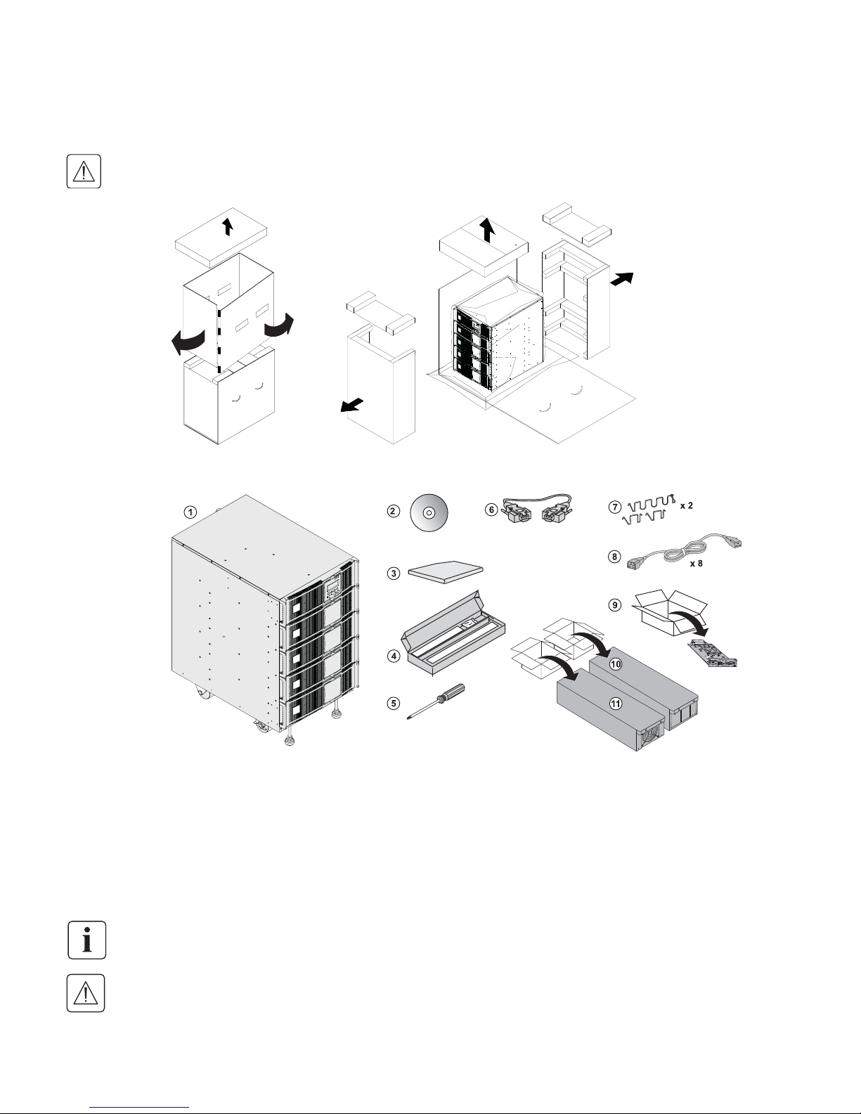
Unpacking and contents check
Unpacking
Contents check
Keep the packaging parts for wheels removal.
(
(1) MX FRAME 15 000 RT or 20 000 RT UPS.
(2) Solution-Pac power management suite CD-ROM.
(3) Product documentation.
(4) Rack mounting kit
(5) Screw driver.
(6) RS232 communications cable
(7) 4 cable lockers.
(8) 8 IEC 10A output cables.
(9) Network Management card
(10) 3 or 4 Battery sub-modules (3 for 15 000 RT, 4 for 20 000
RT)
(11) 3 or 4 Power sub-modules (3 for 15 000 RT, 4 for 20 000
RT)
Packaging must be destroyed according to waste management standards. Recycling icons are displayed for easy
selection.
A dangerous voltage is present inside the power module and the battery module. Any operations to be carried out
on these modules must be done so by qualified staff.
34008486EN/AC - Page 13
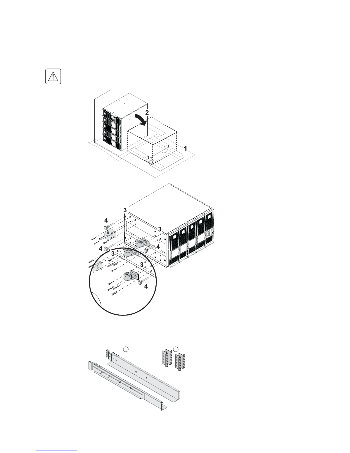
2. Installation
Rack mounting
Wheels removal
Rack mounting kit
The battery sub-modules and power sub-modules must no be mounted yet.
It is not allowed to install the UPS or battery module in a hermetically closed environment without any exchange of
air.
1 - Use packaging as shown.
2 - Place MX Frame on its side.
3 - Remove the 4 screws of the 4 wheels.
4 - Remove the feet
Rack mounting kit content (19" enclosure)
(1) Telescopic rails, 639 mm to 1005 mm
length (27.36’’ to 39.96’’)
(2) Front mouting brackets
1 2
34008486EN/AC - Page 14
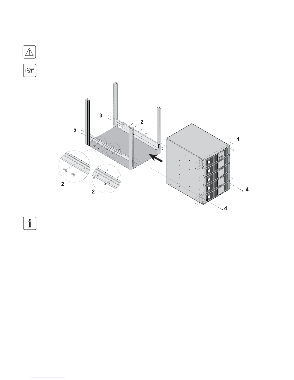
2. Installation
UPS module rack mounting
The battery sub-modules and power sub-modules must no be mounted yet.
It is not allowed to install the UPS or battery module in a hermetically closed environment without any exchange of
air.
Follow steps 1 to 4 for rack mounting the UPS onto the rails.
The rails and the necessary mounting hardware are supplied by EATON.
Note for step 1: it is possible to adjust the position of both front mounting ears.
 Loading...