

Eaton MX 4000 RT, MX 5000 RT Installation And User Manual

www.eaton.com
Installation and user
manual
English
Français
Deutsch
Italiano
Español
Nederlands
MX
4000 RT
5000 RT
Pulsar Series
34008030EN/AD - Page 3
Introduction
Environmental protection
EATON has implemented an environmental-protection policy.
Products are developed according to an eco-design approach.
Substances
This product does not contain CFCs, HCFCs or asbestos.
Packing
To improve waste treatment and facilitate recycling, separate the various packing components.
◗ The cardboard we use comprises over 50% of recycled cardboard.
◗ Sacks and bags are made of polyethylene.
◗ Packing materials are recyclable and bear the appropriate identification symbol .
Follow all local regulations for the disposal of packing materials.
End of life
EATON will process products at the end of their service life in compliance with local regulations.
EATON works with companies in charge of collecting and eliminating our products at the end of their service life.
◗ Product
The product is made up of recyclable materials.
Dismantling and destruction must take place in compliance with all local regulations concerning waste.
At the end of its service life, the product must be transported to a processing centre for electrical and electronic waste.
◗ Battery
The product contains lead-acid batteries that must be processed according to applicable local regulations concerning
batteries.
The battery may be removed to comply with regulations and in view of correct disposal.
Thank you for selecting an EATON product to protect your electrical equipment.
The MX range has been designed with the utmost care.
We recommended that you take the time to read this manual to take full advantage of the many features of your UPS
(Uninterruptible Power System)
Warning: this is a class A UPS product. In a domestic environment, this product may cause radio interference, in wich
case, the user may be required to take additional measures.
Output cables should not be longer than 10 meters.
If the device must be installed in overvoltage category III or IV envoronments, additional upstream overvoltage
protection must be provided for.
Before installing MX, please read the booklet on the required safety instructions. Then follow the indications in this
manual.
To discover the entire range of EATON products and the options available for the MX range, we invite you to visit
our web site at www.eaton.com or contact your EATON representative.
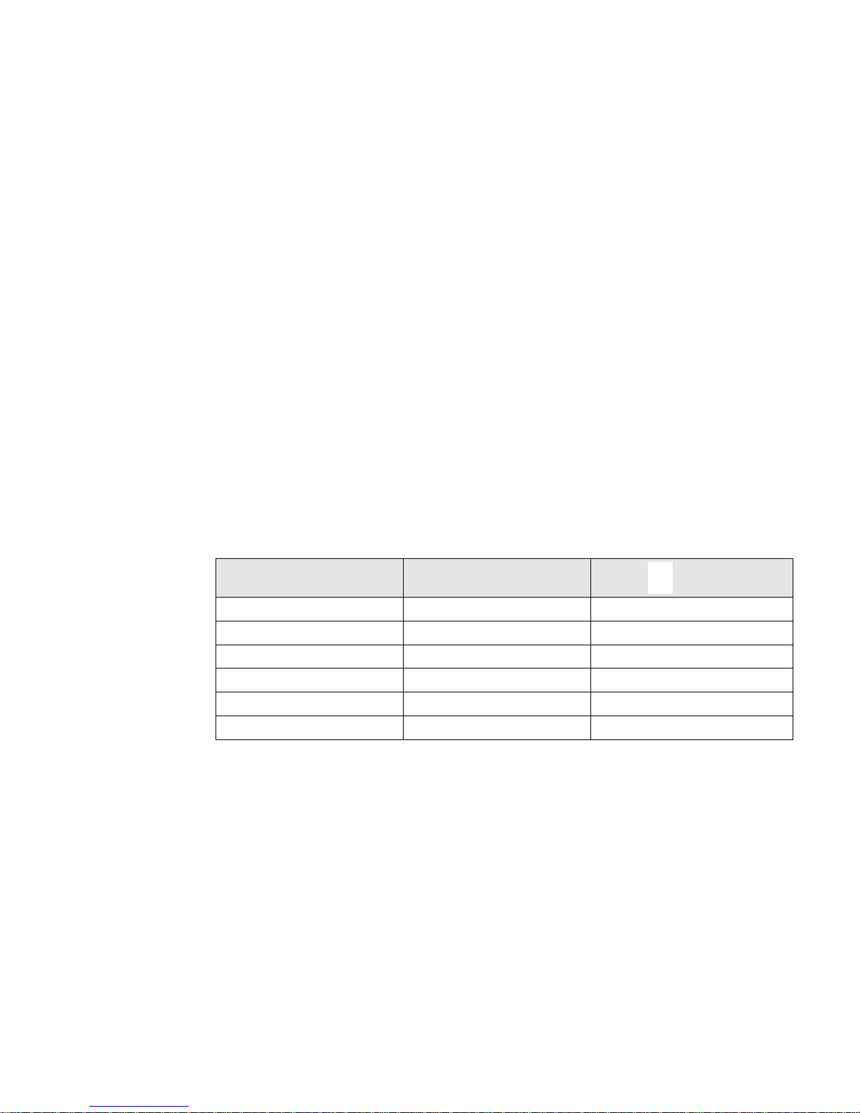
Material Abbreviation Symbol
number
Polyethylene terephthalate PET 01
High-density polyethylene HDPE 02
Polyvinyl chloride PVC 03
Low-density polyethylene LDPE 04
Polypropylene PP 05
Polystyrene PS 06

34008030EN/AD - Page 6
Contents
5. Troubleshooting
5.1 Troubleshooting LEDS (21) and (22) .........................................................................................28
5.2 Troubleshooting not requiring EATON after-sales support.....................................................28
5.3 Troubleshooting requiring EATON after-sales support............................................................29
6. Life Cycle Monitoring (LCM)
6.1 Description ..................................................................................................................................30
Secure your installation power continuity.....................................................................................30
Reset or disable LCM...................................................................................................................30
7. Maintenance
7.1 Hot swapping the power sub-module......................................................................................31
7.2 Hot swapping the battery sub-module ....................................................................................31
7.3 Maintenance on a UPS equipped with the ModularEasy MX module..................................32
7.4 Training centre ............................................................................................................................33
8. Appendices
8.1 Technical specifications..............................................................................................................34
8.2 Glossary.......................................................................................................................................35
34008030EN/AD - Page 7
1. Presentation
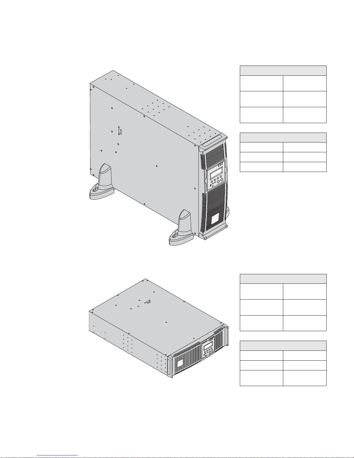
1.1 Standard positions
Tower position
Rack position
Dimensions (H x W x D) in mm / Inches
MX 4000 RT 444.5 x 131 x 700 /
17.5 x 5.16 x 27.56
MX 5000 RT 444.5 x 131 x 700 /
17.5 x 5.16 x 27.56
MX EXB RT 444.5 x 131 x 650 /
17.5 x 5.16 x 25.6
Weights in kg / lbs
MX 4000 RT 57 / 125
MX 5000 RT 57 / 125
MX EXB RT 70 / 154
Dimensions (H x W x D) in mm / Inches
MX 4000 RT 131 x 444.5 x 700 /
5.16 x 17.5 x 27.56
MX 5000 RT 131 x 444.5 x 700 /
5.16 x 17.5 x 27.56
MX EXB RT 131 x 444.5 x 650 /
5.16 x 17.5 x 25.6
Weights in kg / lbs
MX 4000 RT 57 / 125
MX 5000 RT 57 / 125
MX EXB RT 70 / 154
34008030EN/AD - Page 8
1. Presentation
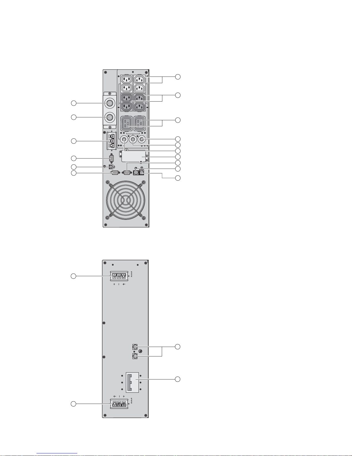
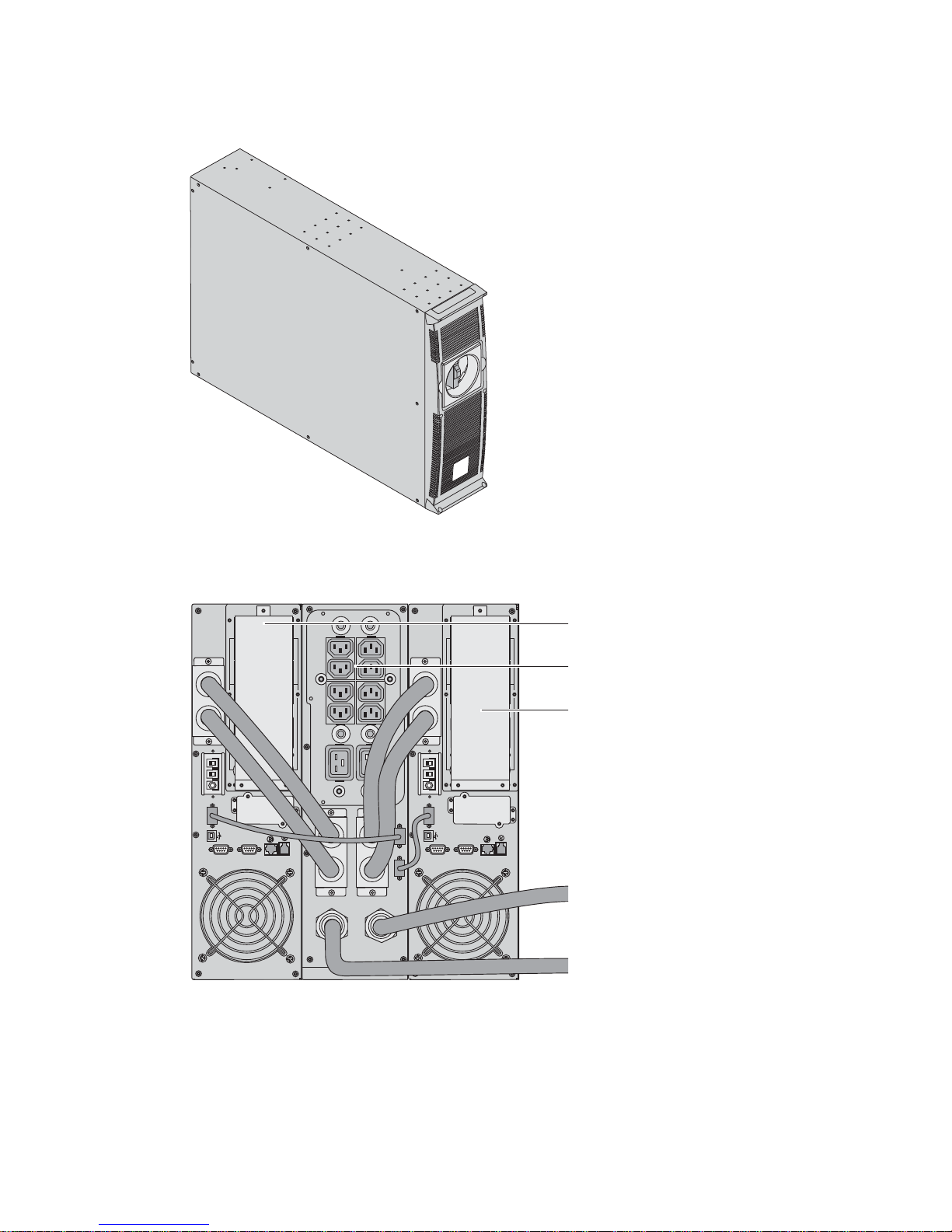
1.2 Rear panels
MX 4000 RT / 5000 RT
MX EXB RT (optional battery module)
(1) Two groups of 2 programmable (10A)
outlets for connection of equipment
(2) Groups of 4 (10A) outlets for
connection of equipment
(3) Groups of 2 (16A) outlets for
connection of equipment
(4) 12A thermal switch
(5) 20A thermal switch
(6) 12A thermal switch
(7) Output terminal block
(8) Normal AC source terminal block
(9) Connector for additional battery
module
(10) Slot for optional communication card
(11) Connector for parallel operation
(12) USB communication port
(13) RS232 communication port
(14) Communication port by relay
(15) Connector for automatic detection of
battery module(s)
(16) Connector for Remote Power Off
control (RPO)
(17) Connectors for automatic detection of
battery module(s)
(18) Connectors for battery modules (to
the UPS or to the other battery modules)
(19) Battery circuit breaker
RS232 CONTACTS
BATTERY
DETECTION
RPO
PARALLEL
SWITCHED
GROUP 2
SWITCHED
GROUP 1
1
2
3
4
5
6
7
8
9
11
12
13
10
14
16
15
BATTERY BREAKER 50Adc
BATTERY
CONNECTOR
180Vdc
BATTERY
CONNECTOR
180Vdc
17
18
18
19
FOR BATTERY
DETECTION
ONLY
34008030EN/AD - Page 9
1. Presentation
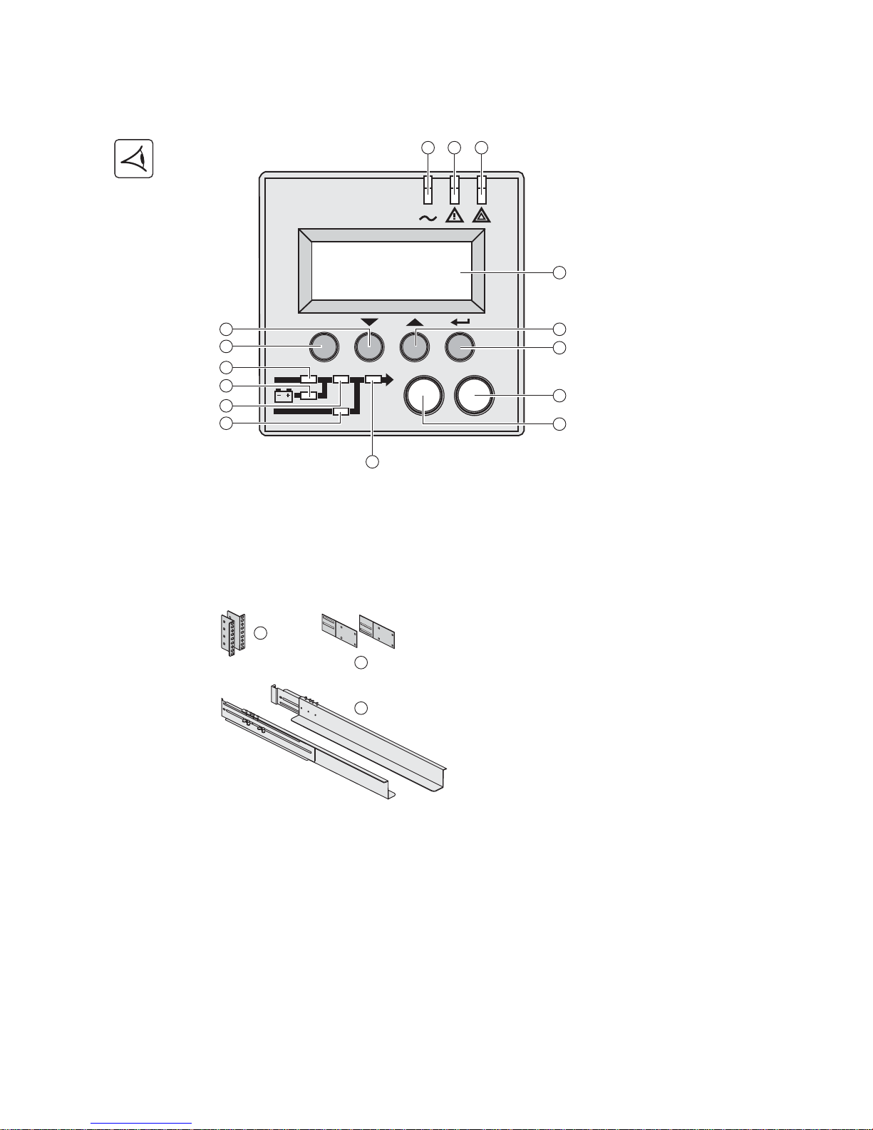
1.3 Display and control panel
1.4 Options
Rack mounting kit
(20) Load protected LED
(21) Downgraded operation LED
(22) Load not protected LED
(23) Alphanumeric display
(24) Escape (cancel) button
(25) (26) Function buttons
(scroll down / scroll up)
(27) Enter (confirm) button
(28) UPS OFF button
(29) UPS ON button
(30) Rectifier LED
(31) Battery LED
(32) Inverter LED
(33) Bypass LED
(34) Load powered LED
Telescopic rails for MX RT mounting in 19’’ enclosure with mounting hardware (part number 68002)
(35) Ear hangup
(36) Rear bracket system for
transportation
(37) Telescopic rails, 639 mm to 1005 mm
length (27.36’’ to 39.96’’)
ESC
IO
24
20 21 22
27
28
29
26
23
25
30
31
32
33
34
35
36
37
34008030EN/AD - Page 10
1. Presentation
ModularEasy
MX ModularEasy enables parallel
operation when combining two MX UPSs.
Consequently you can enhance the
availbility level of your equipment (N+1
redundancy). You can also double your
secured power capacity according to your
needs (migration, network extension...).
In the unlikely event a major fault would
occur, the manual maintenance bypass of
MX ModularEasy would allow the UPS
maintenance without interrupting your
connected equipment.
In single unit mode, MX ModularEasy
combined with one MX UPS adds a
second level of availability to your
installation.
The manual bypass mode allows the
replacement of the UPS without any
interruption to the connected equipment
in case of a major fault that would not be
related to the most critical components of
the UPS (i-e front-accessible, hotswappable Battery and Power SubModules).
Example of MX ModularEasy connected with two UPSs in parallel operation
UPS 1
(MX RT)
MX RT ModularEasy
UPS 2
(MX RT)
UPS output to load
AC Normal input
RS232 CONTACTS
RPO
PARALLEL
SWITCHED
GROUP 2
SWITCHED
GROUP 1
RS232 CONTACTS
RPO
PARALLEL
SWITCHED
GROUP 2
SWITCHED
GROUP 1
BATTERY
DETECTION
BATTERY
DETECTION
34008030EN/AD - Page 11
1. Presentation
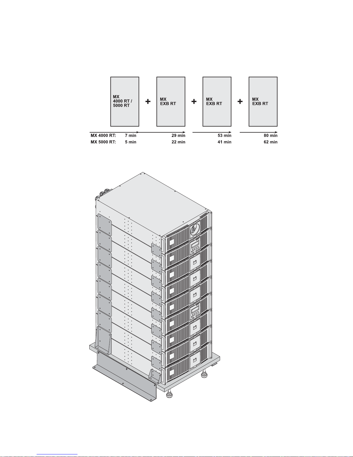
Battery extensions for UPS backup times up to 80 minutes (at full load)
MX RT offers a standard backup time of 5/7 minutes at full load.
To increase backup time, it is possible to connect MX EXB RT modules to the UPSs.
Battery extensions for MX RT
Battery Integration System
Battery extension cable (1,8 m / 6 ft)
This extended battery cable will be used instead of the standard battery cable when battery modules are distant from
each other (located in two different enclosures, for instance).
The Battery Integration System is
intended for extended backup time
configurations to conveniently stack and
secure up to 9 modules on the same cart
(swivel wheels with brakes, leveling feet,
seismic side panels, plates to lock
modules and screws included).
34008030EN/AD - Page 12
2. Installation
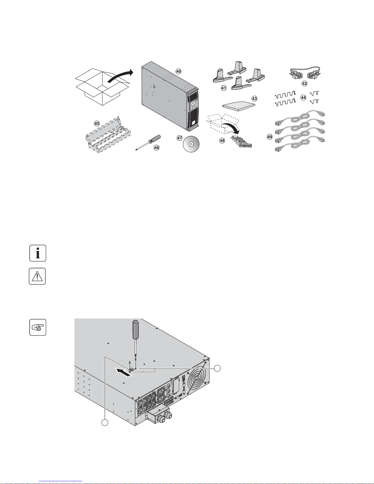
2.1 Unpacking and contents check
2.2 Internal battery connection (Battery start-up)
(40) MX 4000 or 5000 UPS.
(41) Two sets of tower stands.
(42) RS232 communications cable
(43) Product documentation.
(44) 4 cable lockers.
(45) Telescopic rails for rack enclosure with mounting
hardware (optional, or standard with NetPack
version).
(46) Screw driver.
(47) Solution-Pac power management suite CD-ROM.
(48) Network Management card (optional, or standard in
NetPack version).
(49) 4 IEC 10A output cables.
Packaging must be destroyed according to waste management standards. Recycling icons are displayed for easy
selection.
A dangerous voltage is present inside the power module and the battery module. Any operations to be carried out
on these modules must be done so by qualified staff.
1 - Remove the two fixing screws (59) to
free the battery connector.
2 - Push the battery connector so that you
can read "Connected".
3 - Secure the two fixing screws (59).
60
59
34008030EN/AD - Page 13
2. Installation
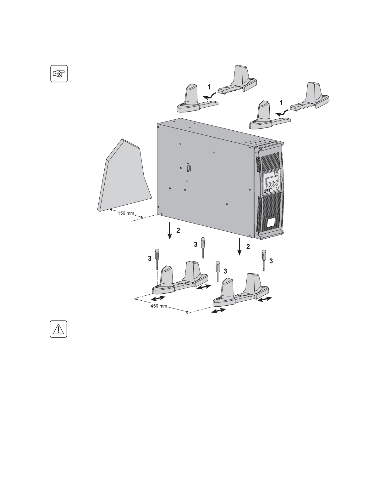
2.3 Installation in tower position
Follow steps 1 to 3 to adjust the tower stands for the upright position.
Always keep 150 mm free space behind the UPS rear panel.
The distance between the tower stands should be 450 mm.
 Loading...