

Eaton MVS Instructional Booklet
Instructional Booklet IB02102006E
Effective May 2011
Supersedes April 2006
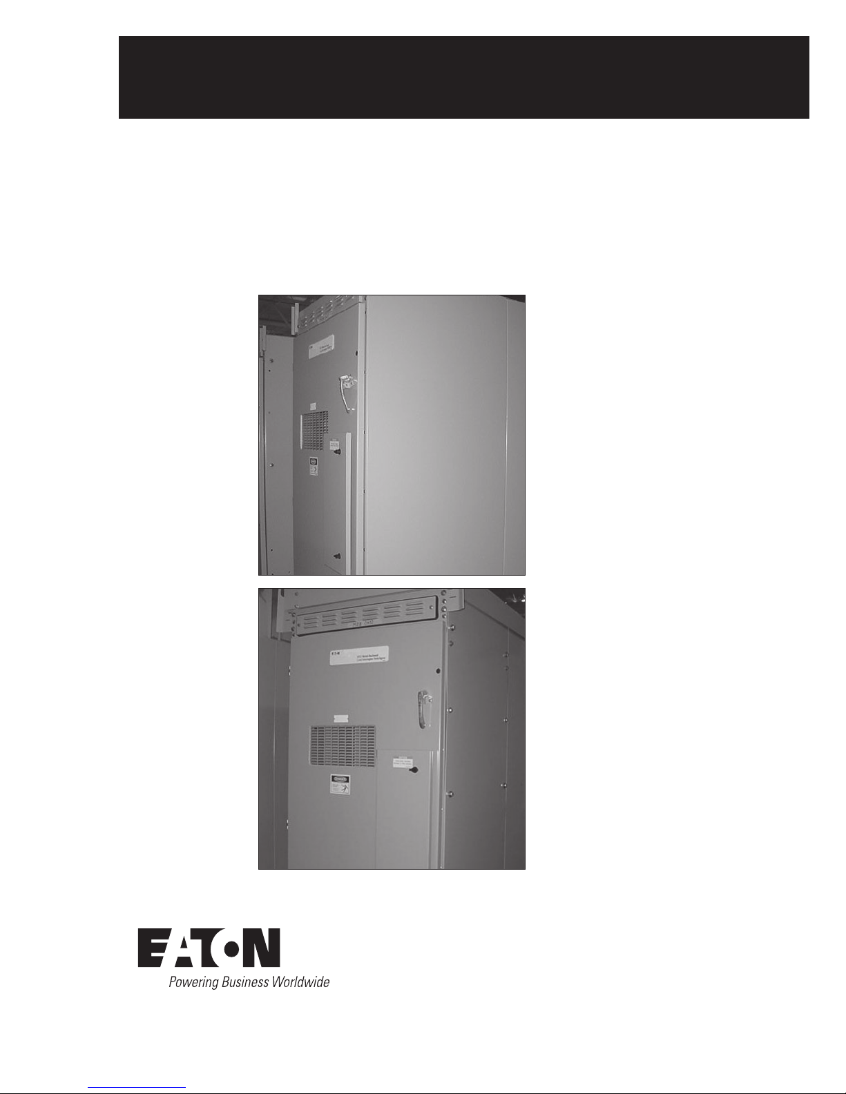
Type MVS (previously WLI)
metal-enclosed switchgear—
4.76 kV, 15.0 kV, 27.0 kV, and 38.0 kV
Description Page
Introduction .............................2
Receiving, handling, and storage ............4
Installation .............................. 5
Operation .............................. 16
Maintenance ........................... 17
Duplex switchgear configuration ............23
Motor operation .........................23
Electromechanical stored energy release
(shunt trip) ..........................25
MVS switchgear bolt tightness for
bus connections and connections to
switch terminal pads ..................28
Common renewal parts ...................28
Instructional Booklet IB02102006E
Effective May 2011
Introduction
Read and understand these instructions before attempting
any installation, operation, or maintenance of this switchgear.
Purpose
This instruction book is expressly intended to cover the installation,
operation, and maintenance of type Medium Voltage Switch
(MVS), previously known as the Westinghouse Load Interrupter
(WLI) metal-enclosed switchgear. It does not purport to cover
all possible contingencies, variations, and details that may arise
during installation, operation, or maintenance of this equipment.
If further information is desired by the purchaser regarding this
particular installation or application information, contact the local
Eaton sales office, see Eaton’s Consulting Application Guide, and
review the appropriate industry standards.
Basic description and application
A type MVS (previously WLI) metal-enclosed switchgear assembly
vertical section consists of an air insulated, three-pole, gangoperated, quick-make, quick-break, load interrupter switch in
a floor-mounted metal enclosure. It can be applied in combination
with power fuses and many other protective devices to provide
safe, economical switching and circuit protection where
infrequent disconnecting means is required.
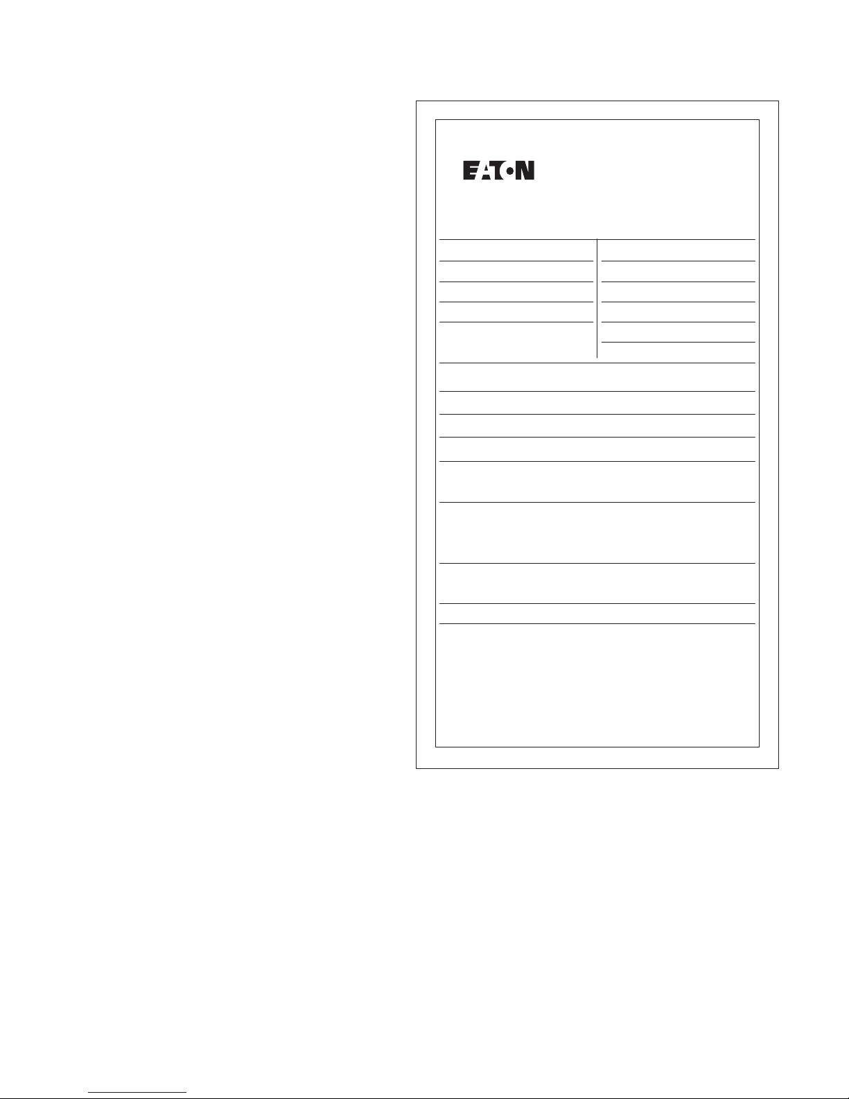
Switchgear identification
A nameplate is located inside the small access door of each type
MVS switchgear vertical section (see Figure 1). Contained on this
nameplate are the Eaton master parts list number and all the
necessary switchgear ratings. This information should be given
to the Eaton sales office if a question should arise concerning
the switchgear or if renewal parts are required. This information
is sufficient for Eaton to find the manufacturing information
for the switchgear.
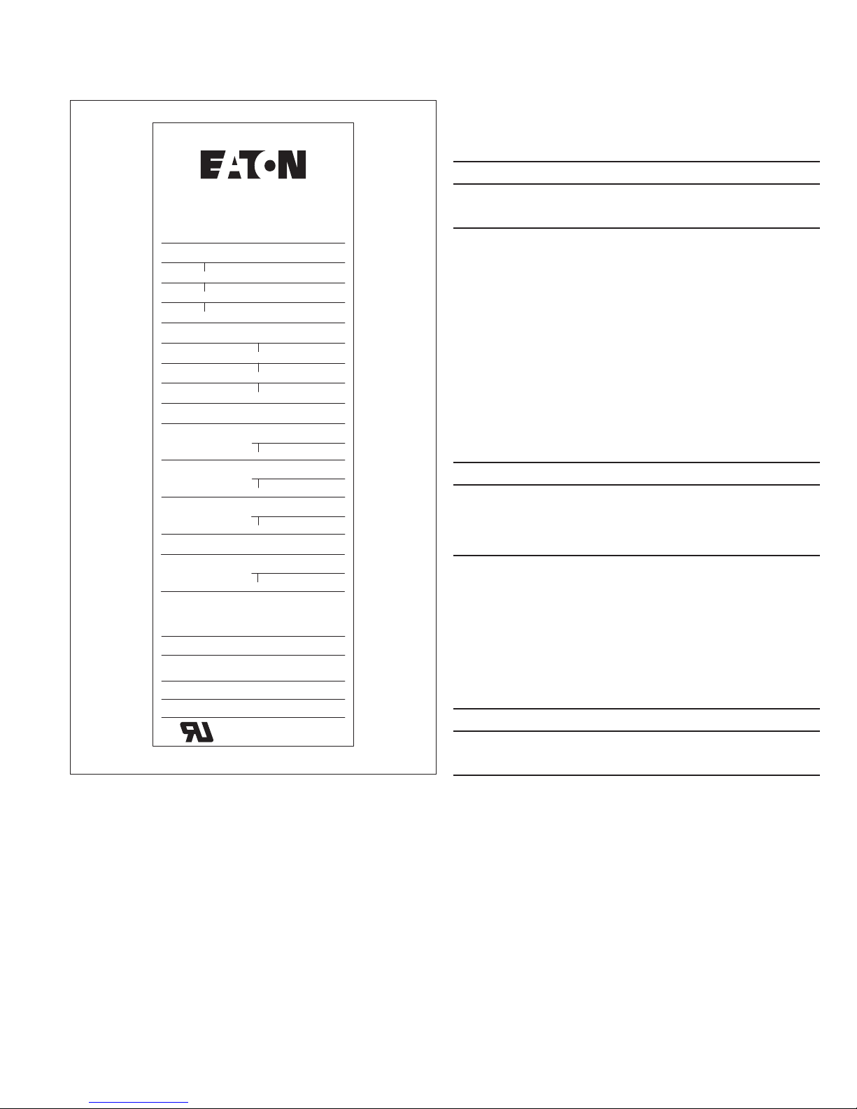
The switch rating nameplate is on the switch mechanism cover.
This nameplate is readily visible when the main enclosure door
is opened. This nameplate contains all of the switch’s ratings and
style number.
Type MVS (previously WLI)
metal-enclosed switchgear—
4.76 kV, 15.0 kV, 27.0 kV, and 38.0 kV
Medium Voltage Metal Enclosed Switchgear Assembly
Type:
Enclosure Type:
Encl. Category:
Mfd. At:
Maximum Continuous
Main Cross Bus Current Ratings
Continuous:
Momentary RMS Asym
Short Time (2 Sec., Sym)
Type Switchgear Assemblies meet the requirements
of industry standards IEEE C37.20.3 and ANSI C37.57
This switchgear vertical section is suitable for use on a circuit
capable of delivering not more than RMS
symmetrical amperes; volts maximum.
See separate label inside for fuse continuous current
ratings when fuses are mounted in this vertical section.
Instructions
Master P.L.:
GO & It:
Section No. Of
Date:
3 Phase 60 Hz.
kV BIL:Operating Volts:
2
EATON CORPORATION www.eaton.com
1A33788H01
Figure 1. Typical Nameplate
Type MVS (previously WLI)
metal-enclosed switchgear—
4.76 kV, 15.0 kV, 27.0 kV, and 38.0 kV
Instructional Booklet IB02102006E
Effective May 2011
Safety features
Type MVS load interrupter switchgear has several built-in features to
reduce hazards and to provide proper operating sequences.
WARNING
EXCEEDING THE NAMEPLATE RATINGS OF MVS SWITCHGEAR MAy CAUSE
PROPERTy DAMAGE, SEVERE INJURy, OR DEATH. MVS SWITCHGEAR
MUST BE OPERATED WITHIN ITS NAME-PLATED RATINGS.
Load Interrupter Switch
Type
Style
Date
Voltage Ratings, kV
Maximum
BIL
3 Phase 60 Hz
Current Ratings, A
Continuous and Load Break
Fault Close and Momentary,
Asymmetrical
Short-Time
(2 seconds)
Fuse Type
Fused Fault Close,
Asymmetrical
Replacement fuses shall be of
the same manufacture, type,
and interrupting rating.
Industry Standards
IEEE C37.20.4 ANSI C37.58
Instructions
Mfd At:
Figure 2. Switch Nameplate
ANSI C37.22
1A33788H02
1. A door interlock prevents opening the enclosure front door while
the switch is in the “Closed” position.
2. A switch interlock prevents manual operation of the handle
mechanism with the door open.
3. A viewing window is provided to visually verify the switch
contact position.
4. Facility is provided for padlocking the switch in the “Open” or
“Closed” position.
5. Facilities are provided for padlocking the door handles closed.
6. Mechanical indicators show whether the switch mechanism is
“Open” or “Closed.”
7. Key interlocks, when provided, force a sequence of operation.
CAUTION
OPERATING AN MVS SWITCH WITH A KEy INTERLOCK BOLT EXTENDED
WILL RESULT IN EQUIPMENT DAMAGE AND MAy ALSO EXPOSE THE
OPERATOR TO BODILy INJURy OR DEATH. THE KEy MUST BE INSERTED
INTO THE INTERLOCK AND ROTATED TO RETRACT THE LOCKING BOLT
BEFORE OPERATING AN MVS SWITCH.
Safety practices
Only qualified electrical workers with training and experience on high
voltage circuits should be permitted to work on this equipment. They
should be familiar with the work to be performed, the safety
equipment required, and the hazards involved.
1. Read and fully understand these instructions before attempting
any assembly, operation, or maintenance of this switchgear.
WARNING
EXCEEDING THE NAMEPLATE RATINGS OF MVS SWITCHGEAR MAy CAUSE
PROPERTy DAMAGE, SEVERE INJURy, OR DEATH. MVS SWITCHGEAR
MUST BE OPERATED WITHIN ITS NAME-PLATED RATINGS.
2. Disconnect all power sources before making any adjustments or
performing maintenance.
3. After opening the switch and before opening the door, use the
viewing window to ensure that all three switch blades are open.
If necessary, use a flashlight to verify that all three contacts
are open.
EATON CORPORATION www.eaton.com
3

Instructional Booklet IB02102006E
Effective May 2011
Type MVS (previously WLI)
metal-enclosed switchgear—
4.76 kV, 15.0 kV, 27.0 kV, and 38.0 kV
WARNING
THERE ARE SEVERAL INTERLOCKS ON THE SWITCHES. THEy ARE
FOR PERSONNEL AND/OR EQUIPMENT PROTECTION. UNDER NO
CIRCUMSTANCES SHOULD THEy BE MADE INOPERATIVE WHEN
SWITCH IS IN SERVICE. TO DO SO MAy CAUSE BODILy INJURy OR
PROPERTy DAMAGE.
4. Never energize the switch without the arc chutes and the
barriers installed.
5. Always be sure that all hardware is in place and bolted
tightly before putting the switch into operation.
6. Before replacing covers, carefully inspect the bus work and
phase barriers to ensure that no tools or other objects are
accidentally left inside the unit.
Revision
Effective May 2011. Supersedes IB02102006E dated April, 2006.
Eaton contact information
For the location of the nearest Eaton sales office or distributor,
call toll-free 1-800-525-2000 or log onto www.eaton.com.
Receiving, handling, and storage
Receiving
A visual inspection—inside and out—should be performed
immediately upon receipt of the switchgear and before removing it
from the truck. Shipping papers should be checked to be sure that
all boxes or other accompanying pieces have been received. If any
damage or shortages are evident, a claim should be filed at once
with the carrier and the nearest Eaton office notified.
The data nameplate for each switchgear assembly is located inside
the mechanism access door. The master parts list number is located
on this nameplate and should be given to the Eaton representative
whenever identification of the assembly is required.
Handling
Removable lifting lugs are provided on the top of the MVS structure
for insertion of hooks to lift the complete structure. This is the only
recommended method of moving the MVS structure.
CAUTION
EXTREME CARE SHOULD BE USED NOT TO DAMAGE OR DEFORM THE
SWITCHGEAR IF OTHER MOVING METHODS ARE EMPLOyED.
Storage
If it is necessary to store the equipment before installation, keep it
in a clean, dry location with ample air circulation and heat to prevent
condensation. Like all electrical apparatus, these units contain
insulation that must be protected against dirt and moisture.
ote:N Outdoor units may be stored outside ONLY if the roof caps are
installed, the space heaters are energized, and any openings
are enclosed.
4
EATON CORPORATION www.eaton.com
Type MVS (previously WLI)
metal-enclosed switchgear—
4.76 kV, 15.0 kV, 27.0 kV, and 38.0 kV
Instructional Booklet IB02102006E
Effective May 2011
Installation
Refer to the shipping list for the location of bus, hardware, and all
other joining and installation material.
Joining type MVS enclosures
Access to MVS switch vertical sections containing switches
Each MVS switch is shipped from the factory in the “Closed” position to maintain alignment during shipping and handling. The safety
interlocking prevents opening of the door of the vertical section
when the switch is closed. In order to gain access to the interior,
be sure that the switchgear is on a true and level surface. To open
a manually operated MVS switch, insert the operating handle and
push down. When the switch opens, the door may be opened. If the
switch is equipped with an electromechanical stored energy release
feature, follow the instructions on the instruction label located inside
the mechanism access door. If the switch is motor operated, it will
function identically to a manually operated switch.
When handling MVS switchgear, be sure that the switches are in
the “Closed” position. Do not operate MVS switches unless they
are setting on true and level surfaces. The definition of level is the
foundation cannot deviate more than ± 0.0125 inches in 36.00 inches
(0.318 mm in 914.4 mm) front to rear, left to right, and diagonally
at any point beneath the switchgear.
Identification of shipping splits
Refer to the front view drawing. Below this drawing, shipping splits
will be identified in relation to group numbers for each vertical
section. Normally, shipping sections will not exceed 154.00 inches
(3911.6 mm) in width.
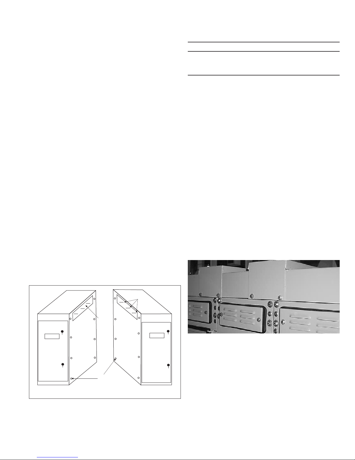
Procedures for joining MVS enclosures at shipping splits
Refer to Figure 3 while completing the following procedure.
Step 1: Remove the eight 0.375–16 inch bolts from each side sheet.
Step 2: Position the shipping sections next to each other. The eight
holes will usually match the holes in the adjacent side sheets but, in
some cases, it may be necessary to use an aligning tool such as a
punch to force the structures into alignment.
Step 3: Bolt the side sheets together using the eight bolts removed
from one side sheet in Step 1.
CAUTION
CLEANING BUS JOINTS WITH ABRASIVE OR CHEMICAL CLEANSERS MAy
REMOVE PLATING. THIS COULD RESULT IN JOINT OVERHEATING.
WIPE THE BUS JOINTS WITH A CLEAN, DRy CLOTH TO CLEAN SURFACES.
Step 5: Bolted connections should be tightened to the torque values
given on page 28.
Installation of roof caps on outdoor units
Roof caps are necessary to complete the roof on all outdoor MVS
switchgear assemblies. Those not factory installed are shipped in
cartons that may be put within one or more of the vertical sections
if there is space, or they will be shipped separately.
Roofs requiring sealing compound
The following procedure details the work to be done to install each
cap on a caulking compound sealed roof joint.
Step 1: Remove the bolts securing the lifting lugs to the MVS
assembly. Remove the lifting lugs then replace the bolts just removed.
Step 2: Place a roof cap in position and start enough screws
(provided loose in a hardware package) to temporarily hold it in place
Step 3: Draw a pencil line down the side(s) on to the roof to mark
the edge(s) of the cap on the roof.
Step 4: Remove roof cap and apply a 0.25 inch (6.35 mm) bead of
caulking (provided by Eaton with the switch) along the inside edge
of the pencil line(s).
Step 5: Hold the edge of the roof cap adjacent to the pencil line,
then rotate it over onto the bead(s) of caulk, aligning it with the bolt
holes in the roof as the action is completed.
Step 6: Install the supplied bolts and gasketed washers (rubber side
toward roof cap) in every bolt hole of roof cap. Tighten the bolts to
5 ft-lbs (6.78 Nm).
Cutout
Mounting
Bolts
Vertical Section to Left Vertical Section to Right
Figure 3. Joining MVS Enclosures
Step 4: Make the main and ground bus connections using splice
plates and the hardware furnished. The busbar is tin- or silver-plated.
To ensure a proper electrical connection, care should be taken to
protect the plating from damage. DO NOT use joint compound.
C
L of
Busbar
Figure 4. Roof Cap Installation
Step 7: Following instructions on the caulking container, smooth out
any excess caulk along the edges of the roof cap.
Step 8: Repeat this procedure until all roof caps have been installed.
For roofs that have edges turned up and formed caps to cover the
edges, it is only necessary to place the appropriate caps over the
roof edges and fasten them in place with the appropriate fasteners.
.
EATON CORPORATION www.eaton.com
5

Instructional Booklet IB02102006E
Effective May 2011
Type MVS (previously WLI)
metal-enclosed switchgear—
4.76 kV, 15.0 kV, 27.0 kV, and 38.0 kV
Connection to type MVS switchgear to a transformer
Physical connection
Indoor assemblies, dry-type, cast coil type, or liquid- filled
type transformers
Holes are predrilled in the side of the MVS structure to match the
holes provided in the transformer.
Outdoor throat connection, liquid-filled transformers
Refer to Figure 5 while completing the following procedure.
Step 1: Remove the sealing ring flange from the MVS switchgear
throat and set it aside.
Step 2: The switch and the transformer should be brought together
to provide spacing of approximately 0.50 inches (12.7 mm) between
the throat flanges.
Step 3: Apply the double-faced adhesive tape supplied with the
MVS switchgear to the outside surfaces of both flanges.
Step 4: Press the felt supplied with the MVS switchgear into place
on the adhesive tape. The felt is to seal against the entrance of dust
and to prevent transmission of the vibration produced by transformer
resonance to the MVS switchgear.
Step 5: Reinstall the sealing ring removed in Step 1.
Medium voltage electrical connections
Connection by cable supplied with the type
MVS switch
•
Cables are NOT factory pre-cut to the proper length. The installer
MUST cut them to fit.
•
Factory cables are unshielded. For 15 kV, 27kV, and 38 kV
applications, they must be properly separated from each
other, from all grounded metal parts, and from the transformer
bushings/terminals of other phases. For 4.76 kV applications,
it is only necessary to install the cables so they will not be
damaged by sharp edges, points, etc.
•
Phasing of the main conductors in type MVS switchgear conforms
to industry standards: that is 1, 2, 3, front to rear, top to bottom,
and left to right at the connection points unless otherwise noted
on the drawings. The installer is responsible for maintaining the
continuity of phasing throughout the system.
•
Lugs are provided with the switchgear for terminating cables
to the transformer bushings/terminals.
Connection by busbar
•
Splice plates and hardware are provided with the MVS switchgear.
The transformer manufacturer supplies the flexible connector.
•
The busbar is tin- or silver-plated. To ensure a proper electrical
connection, care should be taken to protect the plating from
damage. Refer to “Procedures for joining MVS enclosures at
shipping splits” section on page 5 for details.
Connections to an AMPGARDT medium voltage motor
control center (MCC)
Step 1: Holes are predrilled in the side of the MVS switchgear
structure to match the holes provided in the AMPGARD MCC.
Bolt the MVS switchgear and AMPGARD MCC together using
the hardware furnished with the MVS switchgear.
Step 2: Make the bus connections as per “Connections by busbar”
section above.
Figure 5. Transformer Connection to the MVS Switch
6
EATON CORPORATION www.eaton.com

Type MVS (previously WLI)
metal-enclosed switchgear—
4.76 kV, 15.0 kV, 27.0 kV, and 38.0 kV
Instructional Booklet IB02102006E
Effective May 2011
Connections to a medium voltage assembly (MVA)
metal-clad switchgear assembly
Indoor switchgear
Follow the same procedures outlined in “Connections to an
AMPGARD medium voltage MCC” section above.
Outdoor switchgear
Step 1: Position the units side by side. The holes in the MVS side
sheet around the bus cutout will match the holes in the metal-clad
switchgear flange.
Step 2: Press the sponge neoprene gasketing tape, supplied with
the MVS switchgear, onto the flange for the weather-tight seal.
Step 3: Join the enclosures using the bolts supplied with the MVS.
The opposite side of the metal-clad switchgear flange has nuts
welded in place for ease of connection.
Step 4: Make the bus connections as per “Connection by busbar”
section above.
Connection of customer power cables
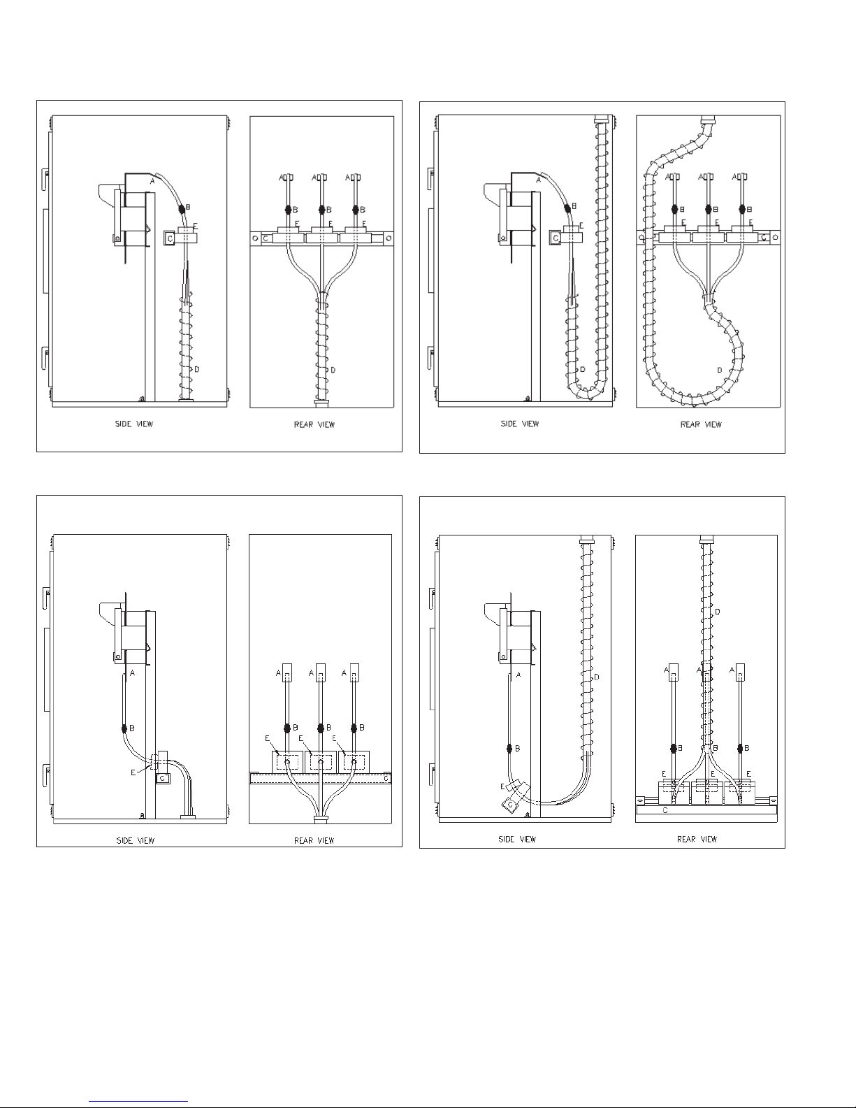
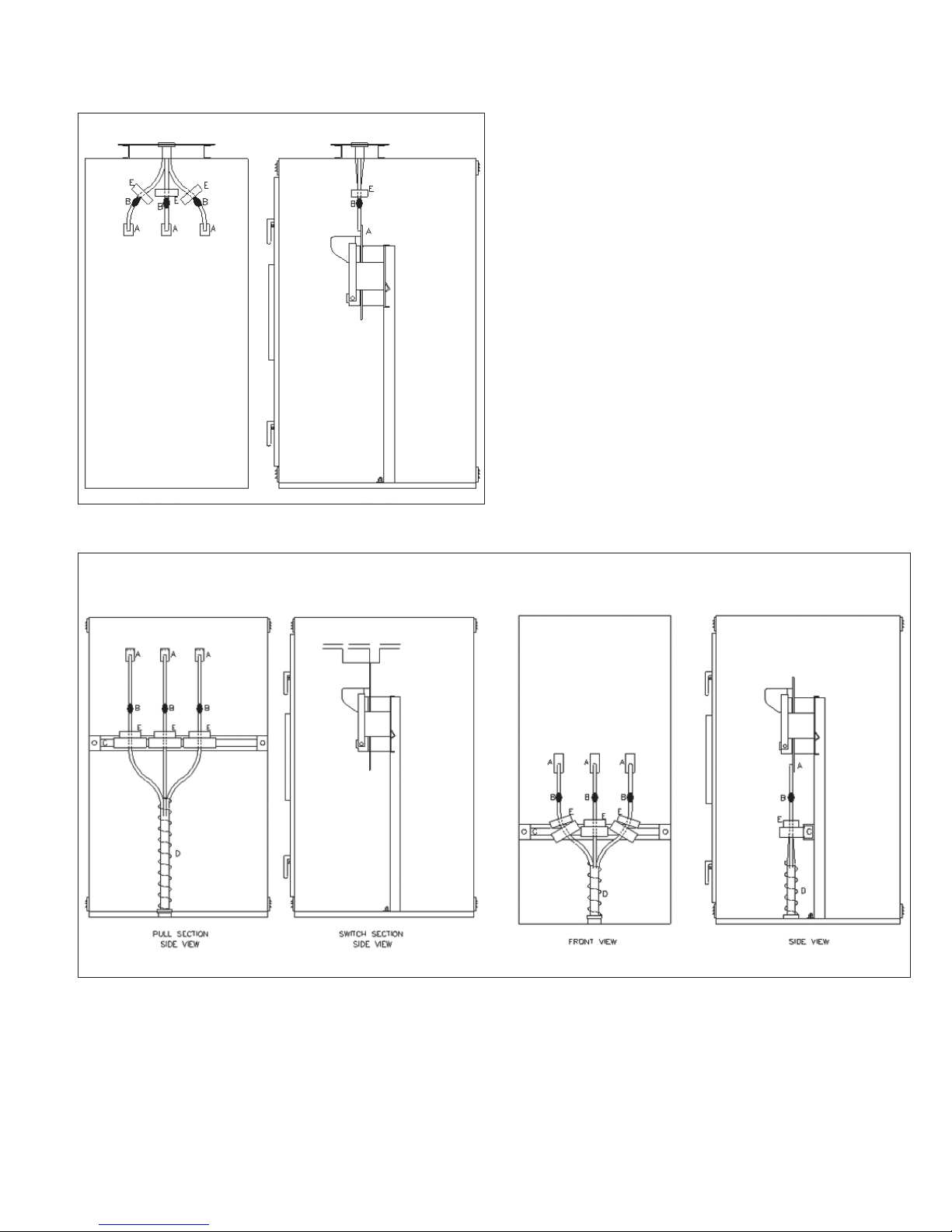
Figure 6 through Figure 15 show the suggested means for connec-
tion of the incoming or exiting cables (maximum of two per phase,
500 kcmil) to the MVS switchgear. The letters in each figure apply
to the itemized subjects (A through E) that follow. All necessary
materials to perform the cable installation are to be provided by
others unless specifically noted otherwise in the detailed instructions or where specifically purchased with the switchgear assembly.
To install the incoming and exiting cables, follow these instructions.
A. The switchgear terminals—For incoming power, the terminals
are usually located at the top of the switch in a vertical section.
For outgoing circuits, the terminals are beneath the switch if
unfused, or on the fuse mounting if fused. Each terminal pad
has a two-hole pattern suitable for either a single hole terminal
or a terminal with a two-hole National Electrical Manufacturers
Association (NEMAT) drilling pattern. The terminal lugs for the
cable, if purchased with the switchgear, will be bolted to the
switchgear terminals. If the terminal lugs are not there, then
they are to be provided by others. The terminals of the switchgear are not suitable to support the weight of the cable. It will
be necessary to support the weight of the cable with the cable
support angle discussed in C below.
B. Cable electrical stress relief devices—The design of MVS
switchgear is based upon use of “pre-formed” type electrical
stress relief devices such as 3-M Quickterm-IIT, RaychemT heat
shrink termination systems, etc. The stress relief devices are to
be provided by others.
C. Cable support channel(s)—The cable support channel(s) is not
supplied by Eaton unless purchased as a feature at the time of
offer. The cable supports may be mounted to suit the geometry
of the installation by drilling holes in the switchgear structure
to suit. The tamper-resistant hardware provided is to anchor the
support channel(s) to the structure. Use the regular hardware to
fasten the channel(s) to the mounting clips. The means to fasten
the cable to this channel(s) is to be provided by others. There are
a large number of commercially available cable support devices
that can be fastened to this channel(s) to support the cable so
that the cable weight is not hanging on the switchgear terminals.
WARNING
FAILURE TO INSTALL THE CABLE SUPPORT MAy RESULT IN DAMAGE TO
THE SWITCHGEAR TERMINALS, WHICH IN TURN MAy RESULT IN MAJOR
EQUIPMENT DAMAGE AND CAUSE SEVERE PERSONAL INJURy OR DEATH.
THE CABLE SUPPORT MUST BE INSTALLED AS INSTRUCTED IN THIS
DOCUMENT.
D. Lacing cord or other equivalent materials/means—The cables
must be lashed together to restrain the cables if a short circuit
should occur. This material is to be provided by others. For large
cables and/or cable reverse loops, it may also be necessary to
lash the cable bundle(s) to the support channel. The views show
this suggested fastening of the cable bundles.
WARNING
FAILURE TO LASH THE CABLES TOGETHER MAy RESULT IN DAMAGE TO
THE SWITCHGEAR, WHICH IN TURN MAy RESULT IN MAJOR EQUIPMENT
DAMAGE AND CAUSE SEVERE PERSONAL INJURy OR DEATH.
THE CABLE MUST BE LASHED TOGETHER AS INSTRUCTED IN THIS
DOCUMENT
E. Current transformer(s)—The current transformer(s) is to be
mounted on the side of the cable support that will physically
support the current transformer(s) so it will not slide down onto
the stress relief devices. The high voltage cable is to be routed
through the current transformer. The H1 side of each current
transformer is to be toward the normal source of electric power.
Each current transformer secondary wiring is terminated at a
plug. This plug is to be placed in the terminal block receptacle to
match the phase on which the current transformer is mounted.
The switchgear terminals will have phase labeling. The secondary
wires are to be fastened to the support channel so they can not
fall into high voltage parts.
EATON CORPORATION www.eaton.com
7
Instructional Booklet IB02102006E
Effective May 2011
Type MVS (previously WLI)
metal-enclosed switchgear—
4.76 kV, 15.0 kV, 27.0 kV, and 38.0 kV
Figure 6. Bottom Cable Entrance (Energy Source), Rear Access
Figure 7. Top Cable Entrance (Energy Source), Rear Access
Figure 8. Unfused Bottom Cable Exit (to Load), Rear Access
Figure 9. Unfused Top Cable Exit (to Load), Rear Access
8
EATON CORPORATION www.eaton.com
Type MVS (previously WLI)
metal-enclosed switchgear—
4.76 kV, 15.0 kV, 27.0 kV, and 38.0 kV
Instructional Booklet IB02102006E
Effective May 2011
Figure 10. Top Cable Entrance (Energy Source), Front Access
Figure 11. Bottom Cable Entrance (Energy Source), Front Access
EATON CORPORATION www.eaton.com
9
 Loading...