

Eaton MTVXKDA20225WRU Instruction Booklet
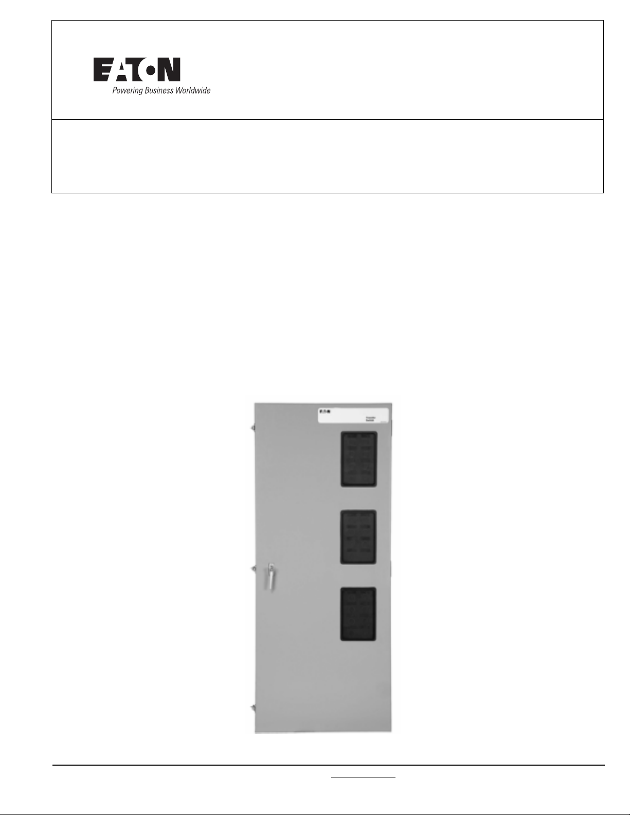
O & M Manual for 30-1000 Amperes
Manual Transfer Switch
Instruction Booklet
Description Page
Introduction . . . . . . . . . . . . . . . . . . . . . . . . . . . . . . . 2
Receiving, Handling, and Storage . . . . . . . . . . . . . . . . . 5
Equipment Description. . . . . . . . . . . . . . . . . . . . . . . . . 6
Installation and Wiring . . . . . . . . . . . . . . . . . . . . . . . . 10
Operation . . . . . . . . . . . . . . . . . . . . . . . . . . . . . . . . . 17
Testing and Problem Solving . . . . . . . . . . . . . . . . . . . . 18
Maintenance . . . . . . . . . . . . . . . . . . . . . . . . . . . . . . . 19
IB140058EN For more information visit: www.eaton.com
Instructional Booklet
Page 2 Effective: March 2016
O&M Manual for 30-1000 Amperes
Manual Transfer Switch
Section 1: Introduction
WARNING
READ AND UNDERSTAND THE INSTRUCTIONS CONTAINED HEREINAFTER BEFORE ATTEMPTING TO UNPACK, ASSEMBLE, OPERATE, OR
MAINTAIN THIS EQUIPMENT.
HAZARDOUS VOLTAGES ARE PRESENT INSIDE TRANSFER SWITCH
ENCLOSURES THAT CAN CAUSE DEATH OR SEVERE PERSONAL
INJURY. FOLLOW PROPER INSTALLATION, OPERATION, AND MAINTENANCE PROCEDURES TO AVOID THESE VOLTAGES.
TRANSFER SWITCH EQUIPMENT COVERED BY THIS INSTRUCTION
BOOK IS DESIGNED AND TESTED TO OPERATE WITHIN ITS NAMEPLATE RATINGS. OPERATION OUTSIDE OF THESE RATINGS MAY
CAUSE THE EQUIPMENT TO FAIL RESULTING IN DEATH, SERIOUS
BODILY INJURY, AND/OR PROPERTY DAMAGE. ALL RESPONSIBLE
PERSONNEL SHOULD LOCATE THE DOOR MOUNTED EQUIPMENT
NAMEPLATE AND BE FAMILIAR WITH THE INFORMATION PROVIDED
ON THE NAMEPLATE. A TYPICAL EQUIPMENT NAMEPLATE IS
SHOWN IN FIGURE 1.
1.1 Preliminary Comments and Safety Precautions
This technical document is intended to cover most aspects associated with the installation, application, operation, and maintenance
of the Automatic Transfer Controller (ATC-300) Controlled ATS
with ratings from 30 through 1000 amperes (A). It is provided as
a guide for authorized and qualified personnel only. Please refer to
the specific WARNING and CAUTION in Section 1.1.2 before proceeding. If further information is required by the purchaser regarding a particular installation, application, or maintenance activity,
an Eaton representative should be contacted.
1.1.1 Warranty and Liability Information
No warranties, expressed or implied, including warranties of fitness for a particular purpose of merchantability, or warranties arising from course of dealing or usage of trade, are made regarding
the information, recommendations and descriptions contained
herein. In no event will Eaton be responsible to the purchaser or
user in contract, in tort (including negligence), strict liability or
otherwise for any special, indirect, incidental or consequential
damage or loss whatsoever, including but not limited to damage or
loss of use of equipment, plant or power system, cost of capital,
loss of power, additional expenses in the use of existing power
facilities, or claims against the purchaser or user by its customers
resulting from the use of the information and descriptions contained herein.
1.1.2 Safety Precautions
All safety codes, safety standards, and/or regulations must be
strictly observed in the installation, operation, and maintenance of
this device.
Figure 1. Typical Manual Transfer Switch Equipment Nameplate.
Note: All possible contingencies which may arise during installation, opera-
tion or maintenance, and all details and variations of this equipment do no
purport to be covered by these instructions. If further information is desired
by purchaser regard- ing the particular installation, operation or maintenance of particular equipment, contact a Eaton representative.
WARNING
THE WARNINGS AND CAUTIONS INCLUDED AS PART OF THE PROCEDURAL STEPS IN THIS DOCUMENT ARE FOR PERSONNEL
SAFETY AND PROTECTION OF EQUIPMENT FROM DAMAGE. AN
EXAMPLE OF A TYPICAL WARNING LABEL HEADING IS SHOWN
ABOVE TO FAMILIARIZE PERSONNEL WITH THE STYLE OF PRESENTATION. THIS WILL HELP TO INSURE THAT PERSONNEL ARE ALERT
TO WARNINGS, WHICH APPEAR THROUGHOUT THE DOCUMENT.
IN ADDITION, WARNINGS AND CAUTIONS ARE ALL UPPER CASE
AND BOLDFACE.
CAUTION
COMPLETELY READ AND UNDERSTAND THE MATERIAL PRESENTED IN THIS DOCUMENT BEFORE ATTEMPTING INSTALLATION,
OPERATION, OR APPLICATION OF THE EQUIPMENT. IN ADDITION,
ONLY QUALIFIED PERSONS SHOULD BE PERMITTED TO PERFORM
ANY WORK ASSOCIATED WITH THIS EQUIPMENT. ANY WIRING
INSTRUCTIONS PRESENTED IN THIS DOCUMENT MUST BE FOLLOWED PRECISELY. FAILURE TO DO SO COULD CAUSE PERMANENT EQUIPMENT DAMAGE.
For more information visit: www.eaton.com IB140058EN
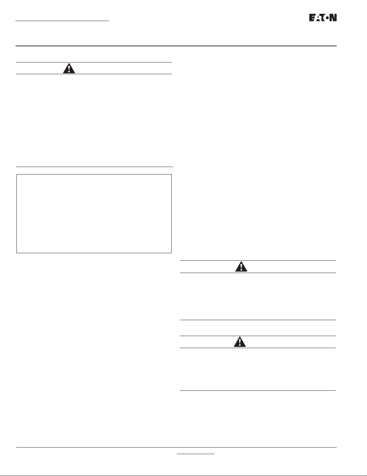
O&M Manual for 30-1000 Amperes
Emergency Source
Normal Source
Load
Manual Transfer Switch
Instructional Booklet
Effective: March 2016 Page 3
1.2 General Information
Transfer switches are used to protect critical electrical loads
against loss of power. The load's normal power source is backed
up by a secondary (emergency) power source. A transfer switch is
connected to both the normal and emer- gency power sources and
supplies the load with power from one of these two sources. In
the event that power is lost from the normal power source, the
transfer switch transfers the load to the secondary (emergency)
power source. Transfer can be automatic or manual, depending
upon the type of transfer switch equipment being used. Once normal power is restored, the load is automatically or manually transferred back to the normal power source, again depending upon the
type of transfer equipment being used (Figure 2)
1.2.1 Transfer Switch Types
Four types of basic transfer switch equipment are available:
Automatic Transfer Switch
Automatic transfer switches automatically perform the transfer
function. They consist of three basic elements:
1. Main contacts to connect and disconnect the load to and from
the power source.
2. A mechanism to transfer the main contacts from source to
source.
3. Intelligence/supervisory circuits to constantly monitor the condition of the power sources and thus provide the intelligence
necessary for the switch and related circuit operation.
Basic Transfer Switch
The basic transfer switch is designed for use with customer furnished controls. It is similar in design to the automatic version
except the intelligence circuit (logic panel) and voltage selection
panel are omitted. All automatic sensing devices, relays or solidstate devices are the customer's responsibility.
Manual Transfer Switch (Manually Operated)
Manual transfer switches provide the main contacts and the transfer mechanism to effect the transfer of the main contacts from
source to source. Transfer of power, however, is accomplished by
true hand operation (not power assisted) of the transfer switch.
This switch is similar to the basic switch in that an intelligence circuit and a motor driven mechanism are not part of the design.
1.2.2 Design Configuration
The Eaton Transfer Switch is a rugged, compact design utilizing
molded case switches to effect the transfer of essential loads
from one power source to another (Figures 3, 4 and 5). Molded
case switches are interlocked to prevent both switches from being
closed at the same time. The versatile design, in addition to standard transfer functions, offers an optional integral thermal and
short circuit protection in either or both switching devices.
Molded case switches and the associated transfer mecha- nism
are usually mounted vertically in the assembly. The vertical configuration (225 - 1000 amperes) is accomplished by utilizing a positive, metallic transfer and interlocking system between the molded
case switches. A horizontally mounted transfer mechanism is utilized with transfer switches 30 - 150 amperes.
The Eaton Transfer Switch was designed with installation ease
and simplified maintenance in mind. Three main panels comprise
the automatic transfer switch design:
• Power Panel
• Voltage Selectin Panel
• Logic Panel
Each panel is independently mounted with interconnecting wiring
terminated in connector plugs to permit individual door or panel
removal without disturbing critical connec- tions. Enclosure
mounting is simplified by utilizing top and bottom mounting
flanges with elongated mounting holes.
For the vertical design, installed power panel positioning bolts,
elongated mounting holes and pre-tapped inserts insure proper
power panel mounting after initial enclosure installation or when
switching from top to bottom entry and vice versa. Refer to Section 4 for mounting and modification details.
1.3 Transfer Switch Catalog Number Identification
Transfer switch equipment catalog numbers provide a signifi- cant
amount of relevant information that pertains to a particu- lar piece
of equipment. The Catalog Number Identification Table (Table 1)
provides the required interpretation informa- tion. An example is
Figure 2. Typical Load Transfer Switch (Circuit Breaker Type)
Schematic.
IB140058EN For more information visit: www.eaton.com
offered to initially simplify the process.
Example: Catalog Number (bolded numbers correspond to position headings in Table 1)
Table 1.
1 to 2 3 4 5 6 7 8 9 to 12 13 14 15
MT V X KD A 3 0300 X S U
The catalog number MTVXKDA30300XSU describes a Manual
transfer switch with the switching devices mounted vertically in
the enclosure. The Eaton Series CT Type HKD is used as the
switching device and is in the form of a 3-pole molded case
switch on each source. The continuous current rating of this
equipment is 300 amperes and applicable at 480 Vac, 60 Hz. The
transfer switch equipment is enclosed in a NEMAT 1 enclosure
and is both UL and CSA listed.
Instructional Booklet
Page 4 Effective: March 2016
Table 2. Transfer Switch Catalog Number Explanation
O&M Manual for 30-1000 Amperes
Manual Transfer Switch
Figure 3. Vertical Design Automatic Transfer Switch Equipment
with Deadfront Cover in Place Over Power Panel (225 - 1000
Amperes)
For more information visit: www.eaton.com IB140058EN
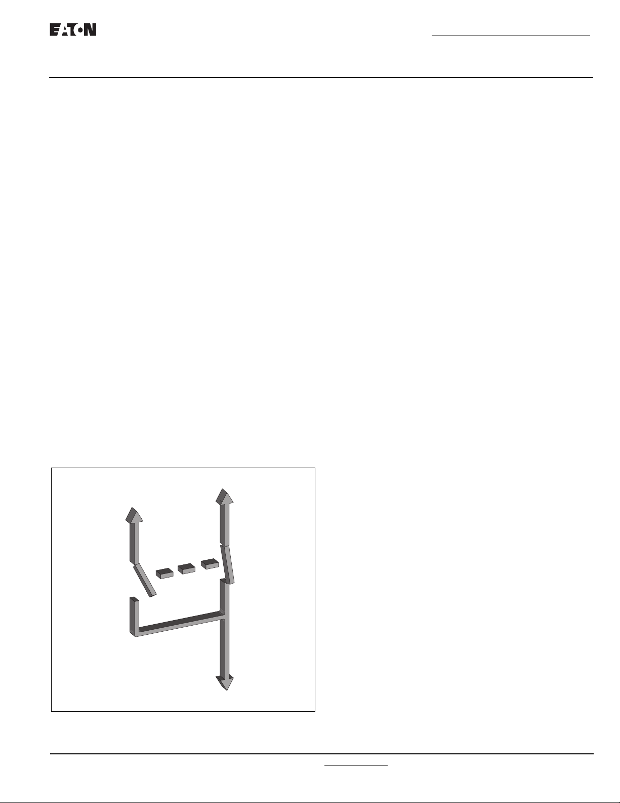
Figure 4. Vertical Design Automatic Transfer Switch Equipment
Shown with Deadfront Cover Removed (225 - 1000 Amperes).
O&M Manual for 30-1000 Amperes
Manual Transfer Switch
Instructional Booklet
Effective: March 2016 Page 5
Section 2: Receiving, Handling, and Storage
2.1 Receiving
Every effort is made to ensure that the ATS equipment arrives at
its destination undamaged and ready for installation. Packing is
designed to protect internal components as well as the enclosure.
Care should be exercised, however, to protect the equipment from
impact at all times. Do not remove the protective packaging until
the equipment is ready for installation.
When the ATS equipment reaches its destination, the customer
should inspect the shipping container for any obvious signs of
rough handling and/or external damage that occurred during transportation. Record any external and internal damage for reporting
to the transportation carrier and Eaton, once a thorough inspection
is complete. All claims should be as specific as possible and
include the Shop Order and General Order numbers.
CAUTION
MAKE NOTE OF THE WARNING LABEL ATTACHED TO THE TOP OF
THE SHIPPING CONTAINER THAT WARNS AGAINST DOUBLE
STACKING TRANSFER SWITCH EQUIPMENT.
Figure 5. Horizontal Design Automatic Transfer Switch Equipment
(30 - 100 Amperes)
1.4 Environmental Conditions
Seismic
With proper installation and by including the appropriate option
which includes specially designed cleats, transfer switches have a
seismic capability which exceeds the worst case Zone 4 required
levels per both the Uniform Building CodeT and the California
Building Code.
Operational Conditions
Normally, a transfer switch is applied indoors in an electrical
equipment room. In the appropriate enclosure, it can be used for
outdoor applications where the equipment is sub- ject to falling
rain, freezing temperatures and 95% humidity (non-condensing).
The ambient temperature range for operation is between -20 and
+70°C.
A shipping label is affixed to the top of the shipping container
which includes a variety of equipment and customer information,
such as General Order Number (GO#) and Catalog Number (Cat#).
Make certain that this information matches other shipping paper
information.
Each transfer switch enclosure is bolted through its top and bottom mounting flanges to a rigid wooden pallet. The pallet is open
at two ends for movement by a fork lift. Heavy duty cardboard
sides surround the enclosure and are further supported with reinforced cardboard corner posts. An egg crate design cardboard protector covers the entire top of the enclosure with additional
cardboard protectors over the indicating light panel and operating
handle. A heavy duty cardboard lid covers the entire opening. The
shipment is secured and further protected with shrink wrap. Do
not discard the packing material until the equipment is ready for
installation.
Once the top packaging is removed from the shipment, the enclosure door can be opened. A plastic bag of docu- ments will be
found within the enclosure, usually attached to the inside of the
door. Important documents, such as test reports, wiring diagrams,
appropriate instruction leaflets and a warranty registration card,
are enclosed within the bag and should be filed in a safe place.
2.2 Handling
As previously mentioned, ATS equipment is packaged for forklift
movement. Protect the equipment from impact at all times and DO
NOT double stack.
Once the equipment is at the installation location and ready to be
installed, packaging material can be removed and discarded. Once
the enclosure is unbolted from the wooden pallet, it can be hand
moved to its installation position. Be careful not to damage the top
or bottom enclosure mounting flanges. Refer to Section 4 of this
manual for specific installation instructions.
IB140058EN For more information visit: www.eaton.com

Instructional Booklet
Page 6 Effective: March 2016
O&M Manual for 30-1000 Amperes
Manual Transfer Switch
2.3 Storage
Although well packaged, this equipment is not suitable for
outdoor storage. The equipment warranty will not be applicable if there is evidence of outdoor storage. If the equipment
is to be stored indoors for any period of time, it should be
stored with its protective packaging material in place. Protect the equipment at all times from excessive moisture, construction dirt, corrosive conditions, and other contaminants.
It is strongly suggested that the package-protected equipment be stored in a climate-controlled environment with temperatures from -20 to 85°C (-22 to 185°F) and with a
relative humidity of 80% or less. DO NOT, under any circumstance, stack other equipment on top of a transfer switch
equipment enclosure, whether packaged or not.
Section 3: Equipment Description
3.1 General
Eaton transfer switch equipment is available in four different
configurations:
• Automatic Transfer Switch
• Maintenance Bypass Transfer Switch
• Manual Transfer Switch (Manually Operated)
• Non-automatic Transfer Switch (Electrically Operated)
Refer to Section 1 for a discussion of the four types. Each
transfer switch is usually supplied in an enclosure, although
un-mounted sub-assemblies can be supplied for mounting by
the customer. Since the enclosed automatic transfer switch
encompasses all transfer switch equipment possibilities, it is
the only specific type that will be discussed in this section.
Figure 6. Typical Vertical Design Power Panel (Unmounted).
The enclosed automatic transfer switch consists of three
basic panels interconnected through connector plugs and
mounted in an enclosure (Figures 4, 5, 15 and 16):
1. Power Panel
2. Voltage Selection Panel
3. Logic Panel.
For more information visit: www.eaton.com IB140058EN
 Loading...