

Eaton MTL83*C Modbus, Crouse-Hinds Series, MTL838C, MTL831C Software Manual
DRAFT - 06 January 2019
MTL83xC Modbus
PC software manual
January 2019
INM MTL83xC PC Modbus Rev 1
Instruction manual
MTL fieldbus networks

ii
INM MTL83xC PC Modbus Rev 1
DRAFT - 06 January 2019
This page left intentionally blank

iii
INM MTL83xC PC Modbus Rev 1
DRAFT - 06 January 2019
CONTENTS
1 INTRODUCTION ............................................................1
1.1 PC Requirements ........................................................................1
2 QUICKSTART GUIDE ........................................................2
3 BACKGROUND TO THE MTL838C .............................................2
3.1 The analog-input multiplexer system .......................................................3
3.2 Configuring the MTL838C .................................................................3
3.3 On-line Configuration .....................................................................4
3.4 Off-line Configuration ....................................................................4
3.5 The PC software .........................................................................4
3.6 Interconnection of the MTL838C ...........................................................5
3.7 Initialization mode .......................................................................5
3.8 Slave, Transmitter and Input addressing .....................................................5
3.8.1 Addressing MTL838C slaves ..............................................................5
3.8.2 Addressing the transmitters of each MTL838C ...............................................6
4 PC SOFTWARE INSTALLATION ........................................................7
5 SOFTWARE OPERATION .............................................................8
5.1 Configuration Overview ...................................................................9
5.2 The MTL838C Tab .......................................................................10
5.2.1 Communication Protocol ................................................................10
5.2.2 Data Format ..........................................................................10
5.2.3 Tag Name ............................................................................11
5.2.4 RS485 Link 1 Address ..................................................................11
5.2.5 RS485 Link 2 Address ..................................................................11
5.2.6 Transmitters Connected ................................................................11
5.2.7 Temperature Units .....................................................................12
5.2.8 Baud Rate ............................................................................12
5.2.9 Line Frequency ........................................................................12
5.2.10 Parity ................................................................................12
5.2.11 Alarm Relay 1 .........................................................................13
5.2.12 Alarm Relay 2 .........................................................................14
5.2.13 Action Buttons ........................................................................14
5.3 The MTL831C #1 Tab ....................................................................14
5.3.1 Input Type ............................................................................15
5.3.2 Safety Drive ..........................................................................15
5.3.3 High Alarm ...........................................................................15
5.3.4 Low Alarm ............................................................................15
5.3.5 Input Zero, Output Zero, Gain ............................................................16
5.3.6 Reading ..............................................................................16
5.3.7 The CJ Channel .......................................................................16
5.3.8 Moving around the Channel List: .........................................................16
5.4 Action Buttons ...................................................................... 17- 18
5.5 Input Calculator ........................................................................19
5.6 The MTL831C #2 Tab ....................................................................20
6 THE MENU .......................................................................21
6.1 File ...................................................................................21
6.2 Edit ...................................................................................22
6.3 Devices ............................................................................23-25
6.4 Help ...............................................................................26-29

iv
INM MTL83xC PC Modbus Rev 1
DRAFT - 06 January 2019
This page left intentionally blank

1
INM MTL83xC PC Modbus Rev 1
DRAFT - 06 January 2019
1 INTRODUCTION
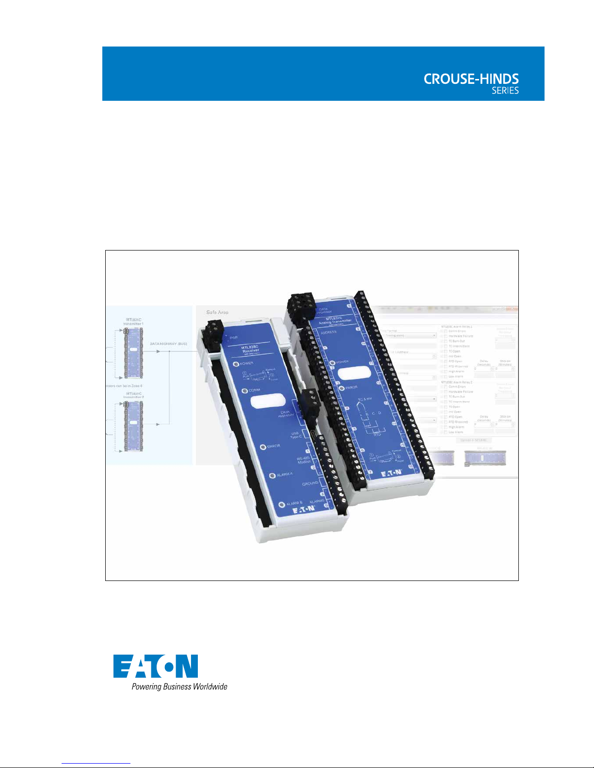
The MTL83xC is a temperature (and mV) measuring system. It consists of an
MTL838C and one or two MTL831C modules. See the datasheet EPS830C
and installation manuals INM838C and INM831C for these modules for further
details. The main interface on the MTL838C which concentrates the data from the
MTL831Cs is Modbus
®
RTU (RS485). A separate document covers the MTL838C
Modbus
®
implementation (INM MTL838C-MBF).
This document covers the operation of the PC software that is used to configure
and monitor the system.
1.1 PC Requirements:
The MTL83xC PC software will run on a Windows® 7, 8, or 10 computer.
This is a small application that doesn’t require a lot of space, memory, or processor
speed. A USB cable is used to connect to the MTL838C (USB-C) – not part of the
MTL838C – purchase separately.
Modbus is a trademark of Schneider Automation Inc., North Andover, MA.

2
INM MTL83xC PC Modbus Rev 1
DRAFT - 06 January 2019
2 QUICKSTART GUIDE
This quickstart guide is written for an MTL83xC system based on an MTL831C
temperature input multiplexer transmitter with an MTL838C multiplexer receiver.
Before the actual installation, it is recommended that new users initially set up a
simple system on the bench to become familiar with the MTL83xC system. The
minimum hardware required for a test system is as follows:
MTL831C Analog transmitter
MTL838C Receiver
MTL5553 Isolator (for hazardous area installations only).
In order to run a test the following equipment will be required:
A PC loaded with MTL83xC Configuration software, Power supply 20 - 35V @
500mA, together with suitable cabling for the following requirements:
Data highway connections (see INM831C / INM838C)
Power supply connections
USB cable
The user will also need the following documentation for wiring information:
INM831C MTL831C installation manual
INM838C MTL838C installation manual
Connect at least one sensor to an MTL831C.
Refer to chapter 5 to configure and test the system.
3
INM MTL83xC PC Modbus Rev 1
DRAFT - 06 January 2019
3 BACKGROUND TO THE MTL838C
3.1 The analog-input multiplexer system
The MTL838C is an analog multiplexer receiver that is used with the MTL831C
hazardous area millivolt input multiplexer transmitter. The status of up to 32 analog
inputs may be communicated from the hazardous area to the safe area via a data
highway, comprised of a simple twisted pair - over distances up to 2000m.
Each data highway must be protected by an MTL5553/5053 digital isolator when
the inputs are located in a Zone 0,1 hazardous area. The MTL831C is typically used
with thermocouple and RTD inputs and is intrinsically safe. It can be mounted in a
Zone 0,1 hazardous area and will accept 16 inputs. For systems that do not require
Zone 0 or Zone 1 installation, the MTL5553/5053 can be eliminated.
Up to two MTL831C transmitters can be combined on a single MTL838C receiver
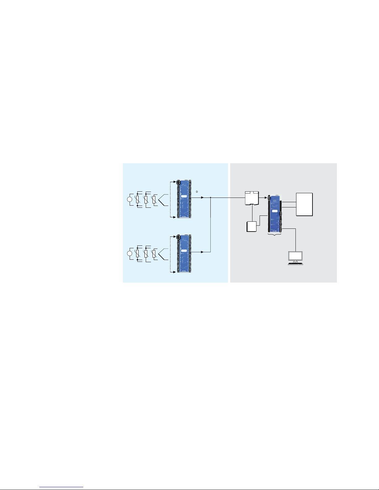
input - up to a total of 32 analog inputs - as shown in Figure 1.
Figure 1 - MTL838C/MTL831C System Diagram
The MTL838C acts as a Modbus slave. It may be connected into any standard
Modbus network, with up to 31 MTL838C slaves on each network. If each unit has
its full complement of 32 analog inputs, the status of a total of 992 analog inputs
may be passed to a Modbus master using a single RS485 network.
3.2 Configuring the MTL838C
The MTL838C must first be configured using software on a PC and the USB
connection. This configures things such as the slave address and communication
parameters. After the initial configuration, the MTL838C is ready to communicate
with the Modbus host. At this point, the remaining configuration may be done in
one of two ways:
• on-line via the Modbus link, direct from the host
• off-line using the PC software and USB connection
Using the PC software is required for initial configuration and recommended for
first time configuration of the measuring channels.
MTL831C
transmitter 1
MTL831C
transmitter 2
mV
Sensors can be in Zone 0
MTL5553/5053
isolator/PSU
mV
MTL838C
receiver
PLC
RS485
RS485
19-30Vdc
Power
PC
(MTL 83xC Configurator Software)
USB
2x SPST
relay
contacts
DATA HIGHWAY (BUS)
Up to 16 THC, RTD,
and mV inputs
potentiometer
Up to 16 THC, RTD,
and mV inputs
potentiometer
Zone 0, 1 or 2
Hazardous Area
Safe Area

4
INM MTL83xC PC Modbus Rev 1
DRAFT - 06 January 2019
3.3 On-line Configuration
Configuring the unit via the Modbus master and the network might seem to be the
simplest method at first sight, but there are a number of practical difficulties with this
configuration technique. This approach means that the user must deal with a number
of complex aspects which require a significant investment of the configurer’s time
before they are understood fully. A further difficulty may be a lack of the necessary
memory space within the Modbus master. If the configuration is likely to be changed
frequently it could even be necessary for the system designer to design specific ‘user
interface’ screens, such as those used by the PC software, to allow changes to be
made by operators. This would be a time consuming and costly task.
For most users, the attraction of being able to use the Modbus master to configure the
unit is that the configuration can be re-sent if the slave’s memory becomes corrupted.
Whilst this is true, it is not possible to avoid the difficulties (and costs) outlined earlier
and the decision to adopt a strategy of configuring via the Modbus master should be
arrived at only after due consideration.
A cost effective compromise would be to perform the initial configuration via the PC
software, and then read the configuration parameters stored in the MTL838C via the
host. The stored parameters could then be re-written to the MTL838C should the
configuration database ever become corrupt.
If a user intends to adopt the on-line configuration method, the calculation of
configuration parameters for storage in the master can be simplified, and the
possibility of ‘human error’ reduced, by using the PC software to input the required
data and data format, and then reading the stored values (encoded correctly in the
required data format) back from the MTL838C via Modbus. The user should still realize
that any subsequent alterations of the parameters will require further use of the PC
software.
3.4 Off-line Configuration
Off-line configuration requires the use of the PC software briefly described below.
Once configured, the configuration parameters are stored in non-volatile memory
within the unit.
3.5 The PC software
By far the simplest method of configuring the MTL838C is using the PC software. This
software has been specifically designed to perform all of the complex calculations that
must be carried out, in order to configure the unit. These calculations are transparent
to the user, and this method provides a convenient and time efficient method.
Alternatively, as explained before, the master could read the configured parameters
after initial off-line configuration and these may then be stored within the host for use
in the event of a database failure.

5
INM MTL83xC PC Modbus Rev 1
DRAFT - 06 January 2019
3.6 Interconnection of the MTL838C
The MTL838C may be connected to a Modbus host in a number of ways.
Two RS485 outputs, Link 1 and Link 2, are provided on the MTL838C. As there are
two outputs the unit can either be connected to a single Modbus master, with dual
redundancy, or connected to two separate Modbus hosts.
The MTL838C will respond on whichever RS485 connection the query is received,
and there is no restriction placed on the simultaneous use of both interfaces. The
Modbus addresses for each Link may only be set by using the PC software.
3.7 Initialization mode
The MTL838C has two distinct modes of operation - normal and initialization.
It will always enter initialization mode during power-up. It can also be triggered by
the detection of internal hardware or software faults, or after receiving an instruction
from the host to reset some or all of the configuration registers.
During initialization, the unit will ignore all commands from the master.
The initialization period will take several seconds to complete all the necessary
operations and calculations. Following successful initialization, the unit will
automatically enter, or return to, normal operation mode.
If a corrupted configuration database is detected during initialization the unit will
revert to a set of default values, and on entering normal operation mode, will issue
exception responses when requested by the host to read input values. Exception
responses will continue to be issued until the unit is re-configured. The need to reconfigure the unit will remain even if the MTL838C is powered down and back up.
If a corrupted configuration is detected, the slave address may be reset. If this
occurs, the user must use the PC software to set the slave address.
Also, when the PC software is communicating with the MTL838C, Modbus
communications are disabled. This is to prevent the possibility of writing to the
configuration database simultaneously from two sources.
3.8 Slave, Transmitter and Input addressing
The following discusses the allocation of addresses to the slaves on the Modbus
network - including the MTL838C - and the allocation of addresses for the
transmitters and inputs connected to each MTL838C.
3.8.1 Addressing MTL838C slaves
Modbus allows slave addresses in the range 1 to 247. JBUS allows slave addresses
in the range 1 to 255. This is the only difference between the two protocols. The
MTL838C will accept addresses in the range 1 to 255 for each Link. Care should be
taken when setting the addresses for each Link using the PC software. For example,
if both Links are connected to the same Host, the addresses should probably be
different.
The Modbus address for each MTL838C slave is set via the PC software. For
reasons of security, it is not possible to set the address of the slave via the
Modbus host.

6
INM MTL83xC PC Modbus Rev 1
DRAFT - 06 January 2019
3.8.2 Addressing the transmitters of each MTL838C
Each MTL831C transmitter accepts up to 16 sensor inputs and there can be one
or two MTL831C transmitters connected to a single MTL838C. The address of
the MTL831C as seen by the MTL838C is determined by whether a jumper wire
is installed on the MTL831C. A jumper wire not installed gives the MTL831C an
address of ‘1’ and a jumper installed gives it an address of ‘2’. The following shows
the sensor numbers used by the MTL838C for a given MTL831C address.
MTL831C Address Sensor Numbers
1 0 - 15
1 32 CJC
2 16 - 31
2 33 CJC
Addressing of the MTL831C transmitters affects which sensor is given which
address in the MTL838C. For example, if only one MTL831C is connected to the
MTL838C but its address jumper is installed, it will be at transmitter address ‘2’ and
the sensor range will be 16 – 3, 1, 33.
It is also important that with two MTL831Cs connected to a single MTL838C, that
one and only one of them has the jumper installed. Otherwise they will both be at
the same address and communication between the MTL831s and the MTL838C
will fail. Likewise, there can be no more than two MTL831Cs connected to a single
MTL838C.
CJC stands for Cold Junction Compensation and reports the average temperature
of the MTL831C circuit board. This is an average of two temperature sensors
and should not be used by the Modbus Host to cold junction compensate
thermocouples. Instead the thermocouple channels should be compensated by the
MTL831C by selecting the correct Input Type.
7
INM MTL83xC PC Modbus Rev 1
DRAFT - 06 January 2019
4 PC SOFTWARE INSTALLATION
The MTL83xC Configuration Software is only available from the Eaton (MTL)
website. Direct your browser to the following website and then locate the
MTL83xC product page. There will be a link on that page to download and install
the software:
www.mtl-inst.com
When you click on the link, your computer will likely warn about the file (setup.exe)
as it is an executable. Allow it to Run the file.
Anti-virus software on your computer may also complain about not knowing
whether the file is safe or not. Tell it to Allow the execution of the file.
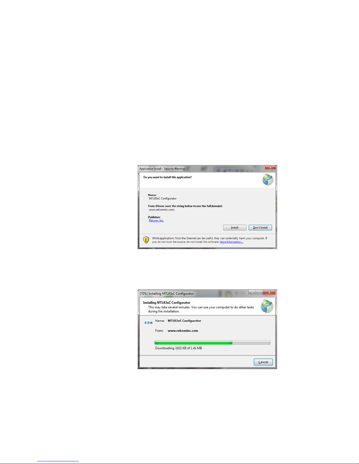
Finally, Windows will want confirmation that you want to install the application. The
following is a sample screen shot of the warning. Notice that Relcom, Inc. is the
publisher of the software as they wrote it for Eaton (MTL).
Allow the installation to proceed.
The application will be downloaded, installed, and will start running.
 Loading...