

Eaton 57605-452, 57601-402, 57602-402, 57601-452, 57600-402 Installation And Operation Manual
®
Durant
AMBASSADOR SERIES COUNT CONTROL
MODELS:
57600-402 (10-15 VDC)
57601-402 (115 VAC)
57601-452 (Red Display)
57602-402 (230 VAC)
57605-452 (24 VAC)
• Six Digit, Single Preset Main Counter
• Six Digit, Single Preset Batch Counter
• Eight Digit Totalizer
• 1/Tau Rate Meter
• Counter and Rate Meter Scaling
• Four User-Configurable Control Inputs
• One Output Relay
• Two Solid State Outputs
• RS-485 Serial Communications
• Red or Green Display
INSTALLATION AND OPERATION
MANUAL Number 57600-902-05
Durant
RST
CLR
®
RUN
PGM
HELP
TABLE OF CONTENTS
1 Introduction
3 Front Panel Features
4 Run Mode Operation
5 Programming
12 Scale Factors
13 Rear Terminal Description
15 Wiring
18 Serial Communications
24 Diagnostics and Troubleshooting
26 Specifications
27 Parts / Accessories
EXIT ENT
SEL
Durant

INTRODUCTION
GENERAL DESCRIPTION
The Durant Ambassador 5760X-402 is a count control device
with three count registers - main counter, batch counter and
totalizer. The main counter has one preset and is typically
used to control cut length, fill quantity, or number of pieces/
container. The batch counter counts the number of times the
main counter has cycled and typically represents values
such as: pieces cut, containers filled, cartons made and etc.
The batch preset is useful for signaling or stopping the
process when the desired amount of product is completed.
The totalizer accumulates the total number of counts processed by the main counter. Its value represents the total
amount of material used by a process or the total number of
pieces processed.
PROGRAMMABLE I/O
One of the unique features of the Ambassador family of
counters is the programmability of the inputs and outputs.
Each of the four inputs can be independently programmed to
perform one of eight functions. The user can also select
which events (counter preset outputs, reset signals, output
control inputs, output timers, and serial commands) cause
each of the three outputs (1 relay and 2 transistor) to pick-up
and drop-out. Any input(s) may be programmed for output
control, however, multiple output control inputs are paralled
into a single output control channel in the unit.
RATE METER
MENU PROGRAMMING
Another unique feature of the Ambassador family of counters
is the menu driven programming. The two line alphanumeric
display prompts programming choices, thus eliminating the
need to remember or look up programming codes. A nonvolatile memory retains programming choices, presets, and
count values while power is removed.
APPLICATION
To better understand the features and capabilities of the
Ambassador, review the simplified block diagram at the top
of the next page and the programming diagrams on pages 6
through 9. Because of the Ambassadors’s versatility, both
programming and wiring decisions must be made before the
counter can be operated. The following sequence of activities is recommended:
1. Answer the following questions:
What should each count register represent?
What should each output control or do?
What effect should each preset have on the outputs?
What should cause each count register to reset?
Which control signals should affect outputs (resets,
programmable inputs, output timers, etc)?
What engineering units should the rate represent?
2. Go through the programming section and mark the choices
required for the application.
In addition to count/control capabilities, a rate meter is
provided to monitor the speed of the incoming count signal.
This rate feature uses the 1/tau method (event time measurement) and can calculate and scale the rate so that even a low
count speed (.1 Hz) can yield accurate rates in engineering
units (ft/sec, gal/min, etc). The rate feature operates simultaneously with the count/control functions.
DISPLAY
All Ambassador Count/Controls are available in green backlit
LCD display and reverse image red LCD display versions.
3. Go through the wiring section and lay out the wiring
required. Remember that wiring is affected by programming.
4. Wire and program the counter as determined in steps 2
and 3 above.
1
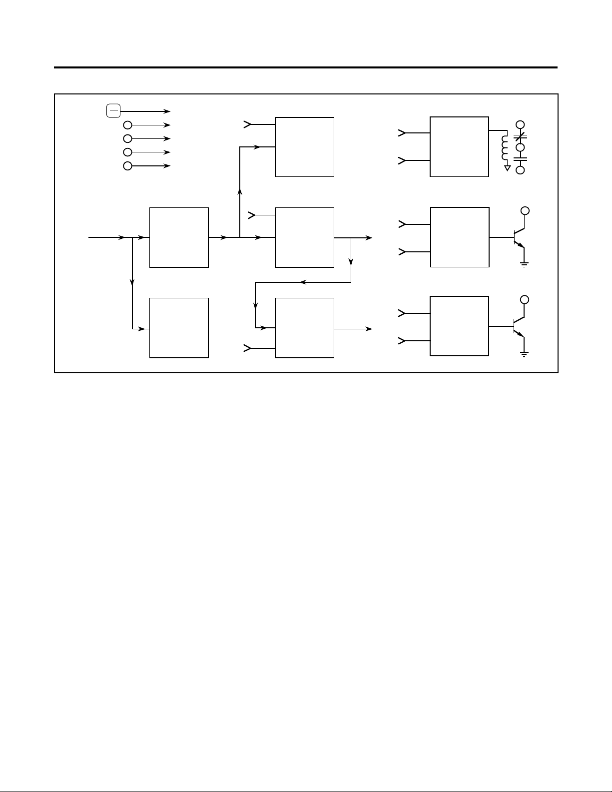
BLOCK DIAGRAM/OVERVIEW
RST
CLR
Inp 1
Inp 2
Inp 3
Inp 4
R
TOTALIZER
C
Pick
Up
Drop
Out
RELAY 1
OUTPUT
LOGIC
R1
Count
Signal
From
Sensor(s)
COUNT
SCALER
RATE METER
RATEMETER
(Rate Scaling)
R/P
C
C
R
COUNT SCALER
Receives the up or down signals and adds or subtracts the
scale factor value to/from the current scaler remainder. The
scaler outputs the integer result as up or down pulses. The
fractional portion of a count remaining is stored in the scaler’s
memory.
MAIN
COUNTER
BATCH
COUNTER
Pick
Main
Preset
Batch
Preset
Up
Drop
Out
Pick
Up
Drop
Out
TRANSISTOR
1 OUTPUT
LOGIC
TRANSISTOR
2 OUTPUT
LOGIC
T1
T2
PROGRAMMABLE INPUTS
The Ambassador unit has five programmable inputs (RST/
CLR key and four terminals). The user may program each
input for one of eight functions (see INPUTS, page 10).
RELAY AND TRANSISTOR OUTPUT LOGIC
MAIN COUNTER
Counts the up and down pulses from the scaler. Every two
milliseconds, the main counter checks if its value has passed
through the preset value (coincidence). For coincidence to
occur, the counter must count up to the preset in the reset to
zero mode and count down to zero in the reset to preset
mode. If coincidence has occurred, the main counter outputs
a pulse on the main preset output. The main counter counts
in the opposite direction if it is programmed to reset to preset.
BATCH COUNTER
Counts up when main counter reaches the main preset.
Every two milliseconds, the batch counter checks if its value
has passed through the preset value (coincidence). If coincidence has occurred, the batch counter outputs a pulse on the
batch output.
These blocks act like latching relays. When the pick-up input
receives a pulse, the output turns on and stays on until it times
out or until the dropout input receives a pulse.
RATE METER BLOCK
The Rate Meter Block measures the time duration of a pulse
or group of pulses received at input A. It uses this measurement along with the rate scaler to calculate the rate in
meaningful units. Internal logic resets the rate meter if the
count direction reverses.
TOTALIZER
Counts the up and down pulses from the scaler. The totalizer
and main counter count in opposite directions if the main
counter is programmed to reset to the preset value.
2
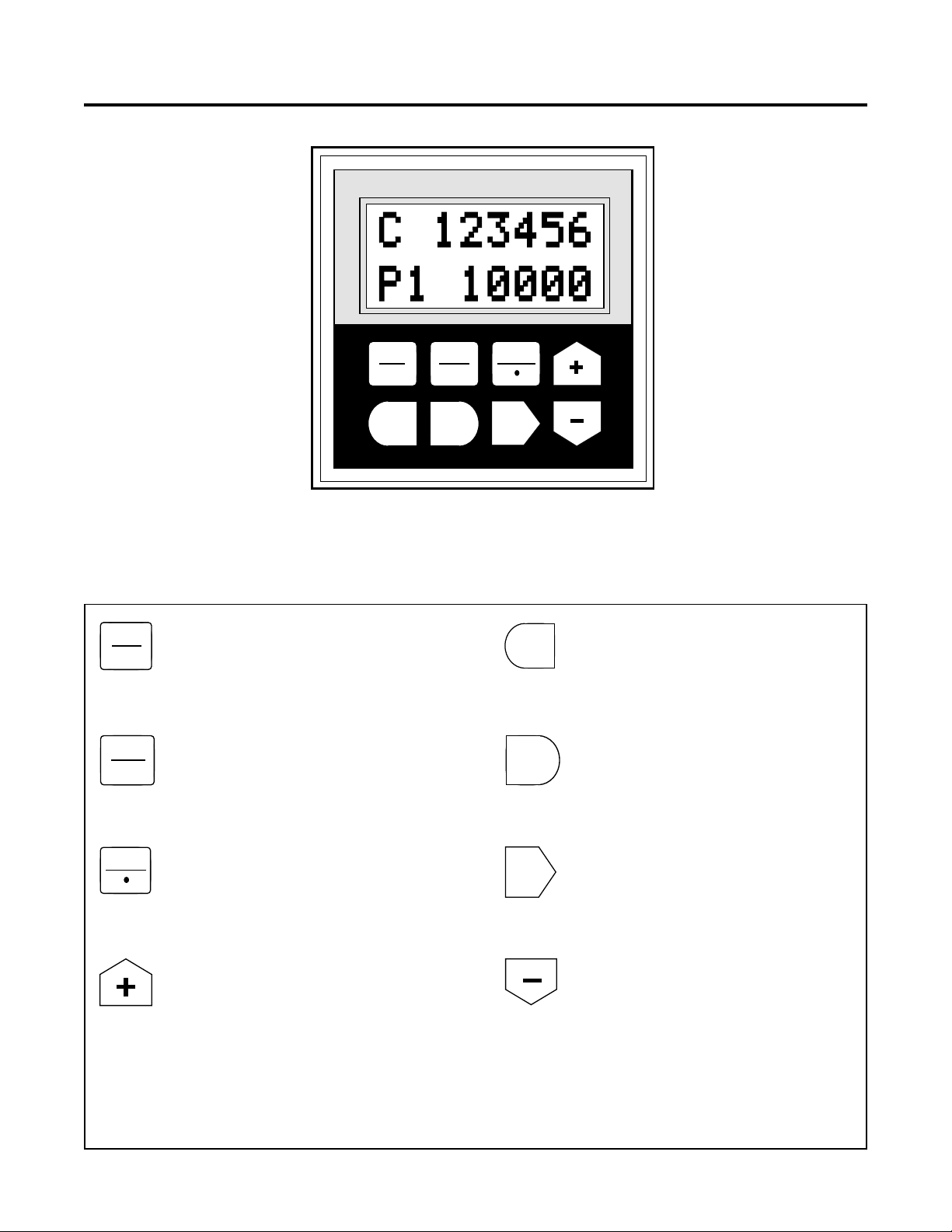
FRONT PANEL FEATURES
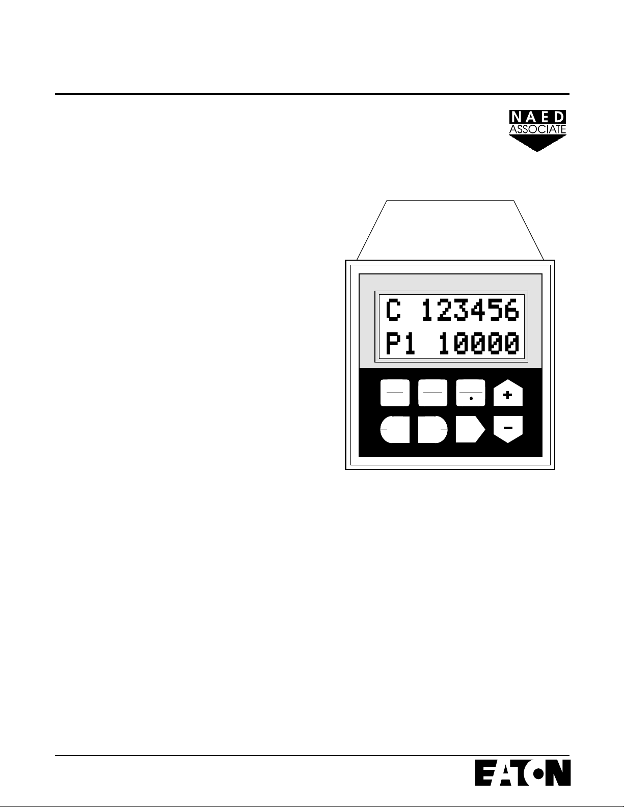
Two line LCD Display - Shows
count, preset, and rate values when
unit is in the run mode. Displays
programming information when the
unit is in the program mode.
RST
CLR
RUN
PGM
Reset/Clear Key - In the run mode this key
can be programmed to reset count values. In
the preset editing mode this key zeros presets that are being changed. In the program
mode it zeros numeric data that is selected
for editing.
Run/Program Key - Press this key followed
by the Enter key (ENT) to enter the program
mode. Pressing this key while in the program
mode returns the control to the run mode.
Durant
RST
CLR
EXIT ENT
®
RUN
PGM
Key Functions
HELP
SEL
EXIT
ENT
Exit Key - In the preset editing mode this key
allows the preset editing process to be exited
without altering the previous preset value. In
the program mode this key exits program
changes that have been selected but not yet
entered.
Enter Key - In the run mode this key causes
preset changes to take effect. In the program
mode it causes the displayed program
changes to be entered.
HELP
Help/Key - In the run mode this key causes
the Help Screens to be displayed. In the
program mode this key is used to set the
decimal point positions for count and rate
scaler displays.
Up Arrow/Plus (+) Key - In the run mode this
key is used to scroll up through the five
different display screens. In the preset editing mode this key adds 1 (increments) to the
value of the selected digit each time it is
pressed. In the program mode this key is
used to step vertically up through the menus
and increment the value of selected digits
when changing numeric values.
Select Key - In run mode this key allows the
SEL
3
editing of presets and selects individual digits
of the preset. In program mode this key is
used to move into more detailed menus and
selects the digits of numeric values needed
for programming.
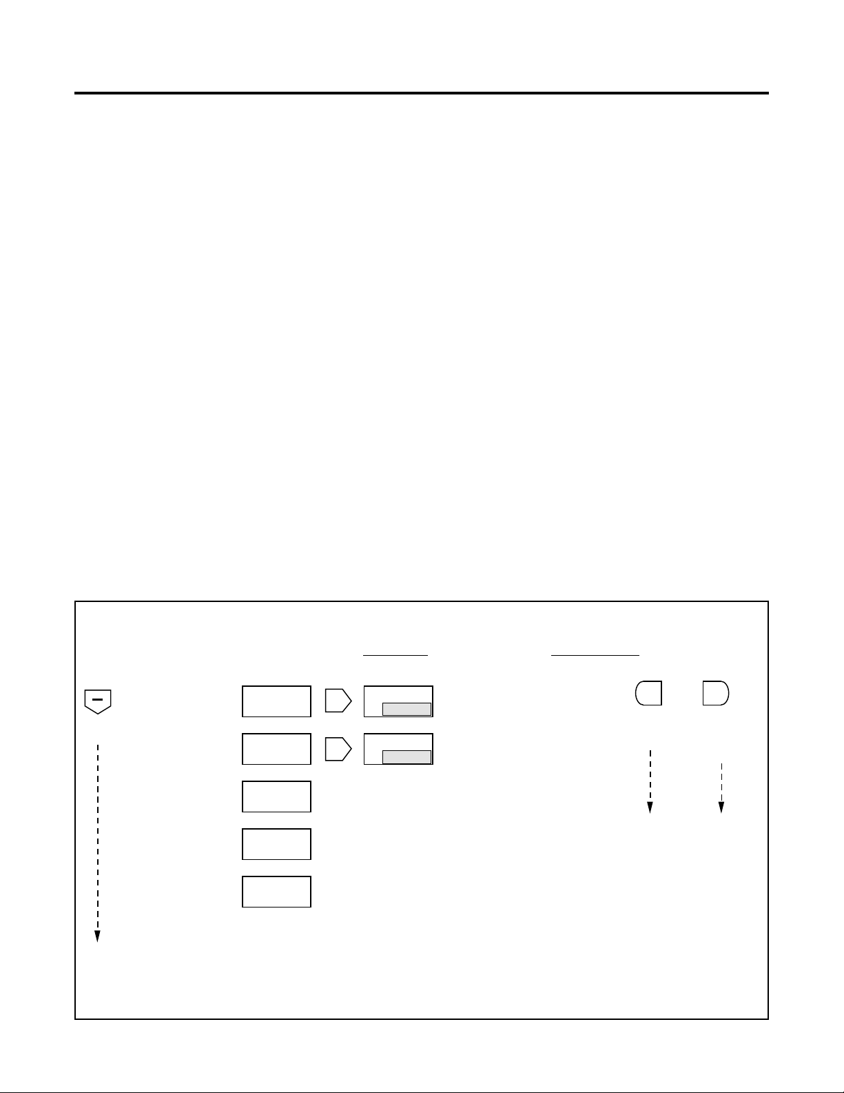
Down Arrow/Minus (-) Key - In the run
mode this key is used to scroll down through
the five different display screens. In the preset editing mode this key subtracts 1 (decrements) from the value of the selected digit
each time it is pressed. In the program mode
this key is used to step vertically down through
the menus and decrement the value of selected digits when changing numeric values.
RUN MODE OPERATION
SELECTING DISPLAY INFORMATION
The Ambassador control has five available run mode displays. Use the up and down arrow keys to select the desired
display.
The selected display will remain on until one of the arrow keys
is pressed to cause a change.
The screen selected for display during run-mode only provides information to the operator and does not affect the
operation of the control.
If power is removed and restored, the unit will power-up with
the display that was last selected.
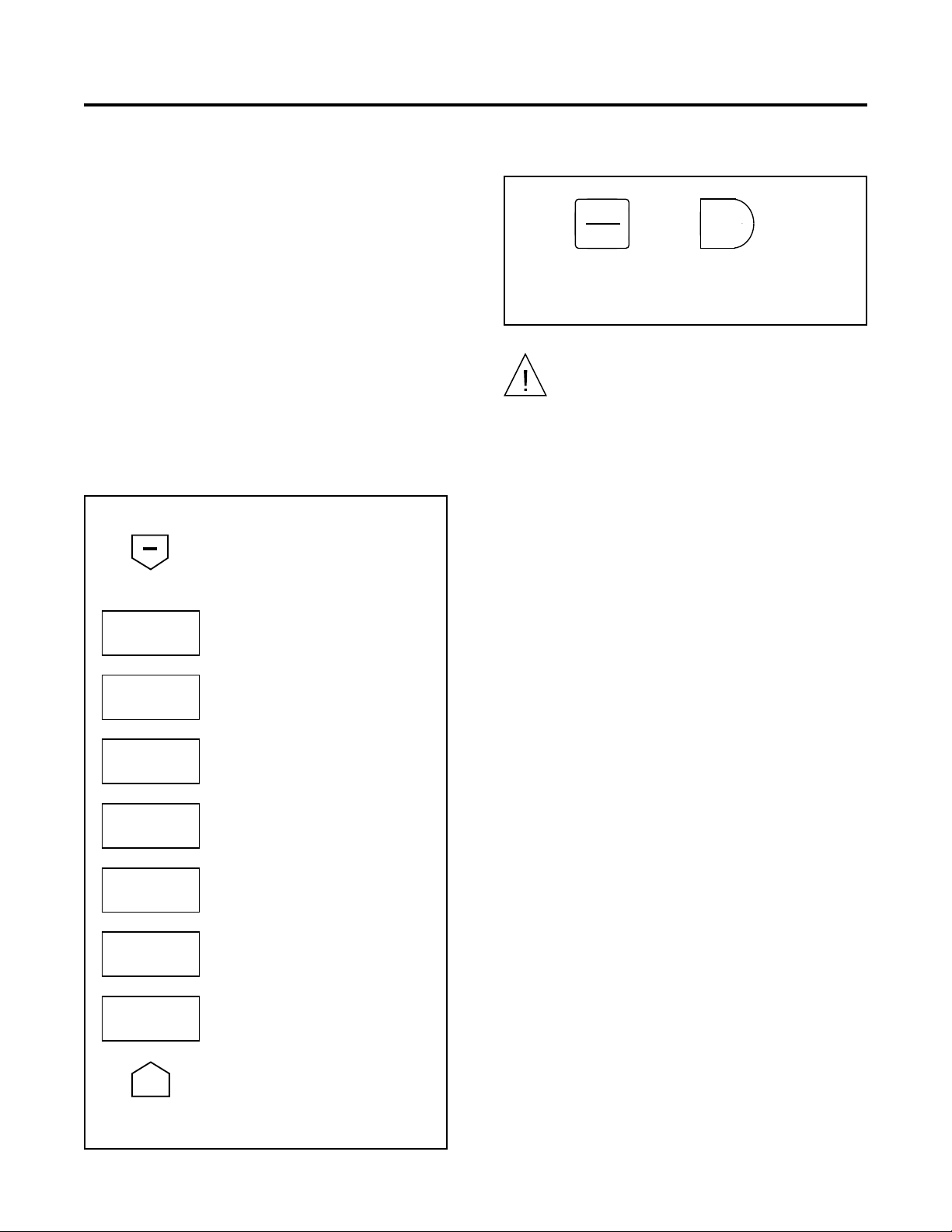
RUN MODE MENUS
The keystroke sequence used to access all of the available
run mode screens and change preset values is shown in a
menu format below.
CHANGING PRESET VALUES
Preset 1 and the batch preset are set as follows:
1. Use the up and down arrow keys to select one of the two
preset screens.
2. Press the SEL key to enter the preset change mode. The
display will show all digits of the preset value. The leftmost digit will flash indicating that it is currently selected.
To set the preset to zero, press the RST/CLR key.
3. Use the SEL key to select the digit to be changed. Each
time the key is pressed, the next digit to the right is
selected. The digit value can then be changed using the up
and down arrow keys.
4. Press the ENT key to enter the new preset value and
return to the run mode screens. Press the EXIT key at any
time to abort preset changes.
All count and control functions continue to operate when
preset values are being changed.
press
to scroll
down
Count & Preset 1
Batch & Batch Preset
Totalizer
Rate Indicator
Count and Rate
Run Mode Menu Illustration
RUN MODE PRESET EDIT MODE
C 123456
1
P 25000
B 500
b
P 1000
TOTAL
12345678
RATE
600.0
C 123456
R 600.0
SEL
SEL
Data field flashes
C 123456
1
P 25000
B 500
b
P 1000
SEL selects digit to be programmed
from left to right. + and - add 1 and
subtract 1 from the selected digit.
SEL selects digit to be programmed
from left to right. + and - add 1 and
subtract 1 from the selected digit.
press
to return
one menu
level
press
ENTEXIT
to enter
data and
return one
menu level
4
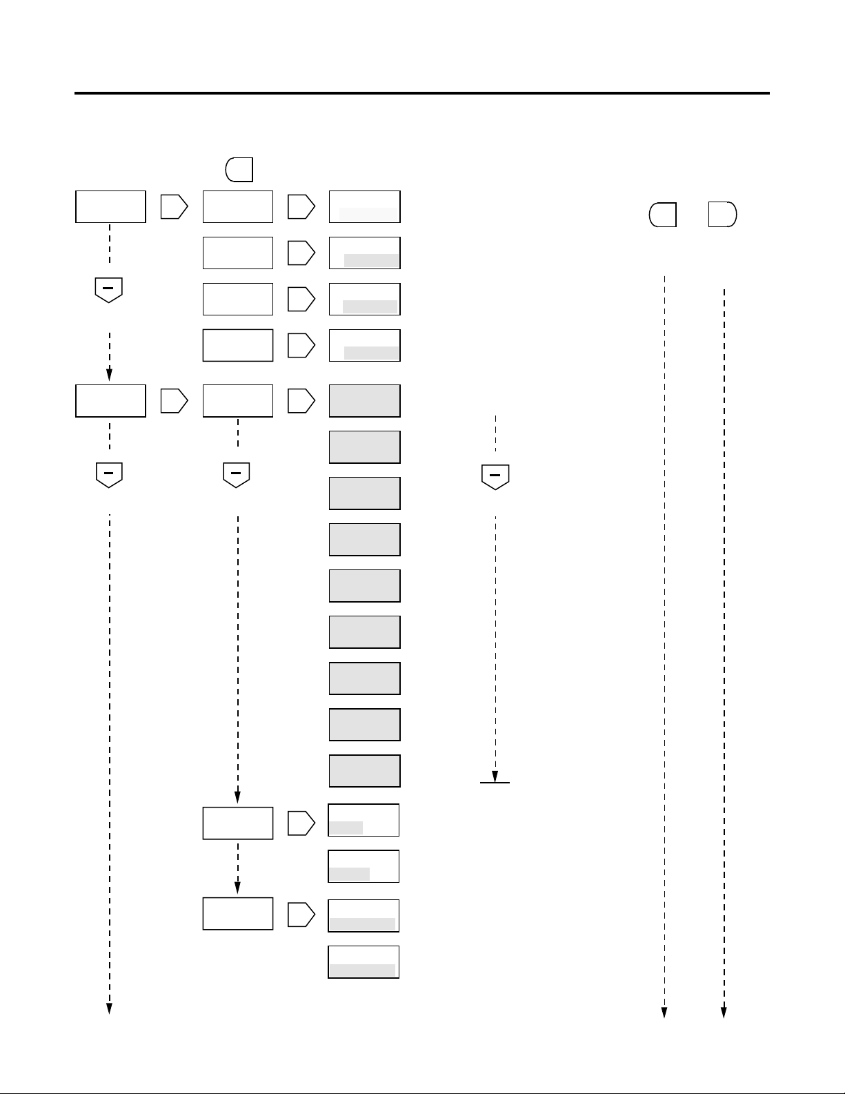
PROGRAM MODE
INTRODUCTION TO MENU PROGRAMMING
The menu programming format used by the Ambassador
series eliminates the need to memorize or look up programming options. Program prompting is provided on the 2 line
alphanumeric display.
The programming menus are organized in a manner much
like an outline. The main menu items are located out to the far
left column and each successive subdivision of these main
items is located one column further to the right.
The keystroke sequences to select all of the programmable
options are shown in the programming charts on pages 7-10.
The seven main menus are shown below.
OVERVIEW OF MAIN MENUS
press
to scroll
down
PROGRAM
SCALERS
Enter count scale factor and decimal
point, rate scale factor and decimal
point.
ENTERING THE PROGRAM MODE
Press
The ENT key must be pressed within five seconds, otherwise the display will return to the last run mode menu.
RUN
PGM
Caution: entering the Program Mode will cause all
outputs to turn off. Make sure process is stopped
before entering the Program Mode.
Then
ENT
To enter
program
mode
PROGRAM
COUNT IN
PROGRAM
INPUTS
PROGRAM
OUT MODE
PROGRAM
SER PORT
PROGRAM
SER OUT
PROGRAM
OPTIONS
press
+
to scroll
up
Select count mode, reset to zero or
reset to preset and auto-recycle operations.
Select the input function to be performed by each to the four programmable inputs.
Select normal or reverse logic, latched
or pulsed, pick-up and drop-out events.
Select the unit I.D. number, baud rate,
parity, and transmission delay.
Select the data items to be transmitted
when a serial group print command
(RCD7) is received.
Select the run mode function of the
front panel RST/CLR key. Restore
factory programming.
5
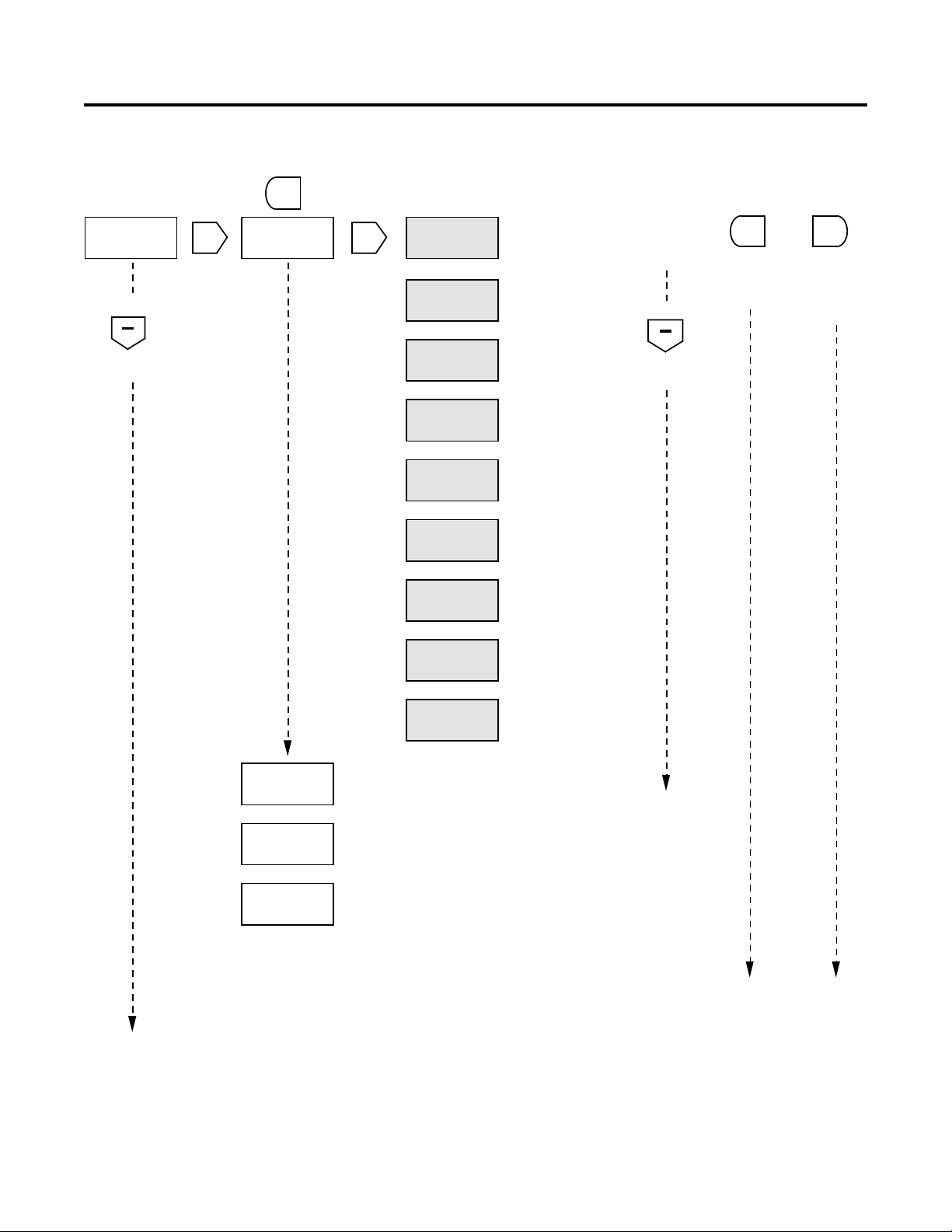
PROGRAMMING SCALERS AND COUNT INPUTS
MAIN MENU SUB MENU EDIT MENU
EXIT
to exit to
main menu
SEL
SEL
SEL
SEL
SEL
Data field flashes
C SCALER
1.00000
C DEC PT
------
R SCALER
1.0000
R DEC PT
------
CONTACT
ADD/SUB
PROGRAM
SCALERS
press
to scroll
down
PROGRAM
COUNT IN
SEL
SEL
press
C SCALER
1.00000
C DEC PT
------
R SCALER
1.0000
R DEC PT
------
CONTACT
ADD/SUB
CONTACT
press
to scroll
down
press
to scroll
down
ADD/ADD
CONTACT
C/DIR
SOLID ST
QUAD x1
See pages 10-11 for detailed description of
programming options.
SEL selects digit to be programmed from left
to right. + and - add 1 and subtract 1 from
the selected digit.
SEL selects decimal point position. HELP/•
SEL selects digit to be programmed from left to
right. + and - add 1 and subtract 1 from the
selected digit. HELP/• programs decimal point.
SEL selects decimal point position. HELP/•
Select Count Input mode using the UP and
DOWN cursors to scroll thru this menu.
press
to scroll
down
press
EXIT
to return
one menu
level
press
ENT
to enter
data and
return one
menu level
RESET TO
ZERO
AUTO CYC
DISABLED
SEL
SEL
SOLID ST
QUAD x2
SOLID ST
ADD/SUB
SOLID ST
ADD/ADD
SOLID ST
Cx1/DIR
SOLID ST
Cx2/DIR
RESET TO
ZERO
RESET TO
P1 ()
AUTO CYC
DISABLED
AUTO CYC
P1 (0)
Select Reset to Zero
or
Select Reset to Preset
Select Auto Cycle Disabled
or
Select Auto Cycle on P1
6
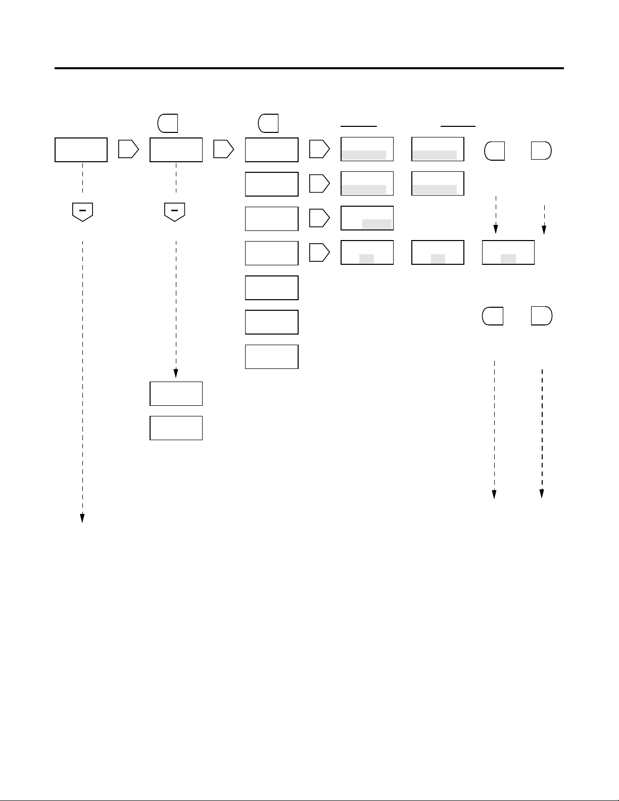
PROGRAMMING CONTROL INPUTS
MAIN MENU SUB MENU EDIT MENU
EXIT
to exit to
main menu
SEL
Data field flashes
INPUT 1
DISABLED
PROGRAM
INPUTS
SEL
press
INPUT 1
DISABLED
INPUT 1
press
to scroll
down
OUT CTRL
INPUT 1
RS C EDG
INPUT 1
RS C LVL
INPUT 1
RS B EDG
INPUT 1
RS T EDG
INPUT 1
STOP CNT
See pages 10-11 for detailed description of
programming options.
Define input function from the
list provided. Repeat for
INPUT 2, INPUT 3, INPUT 4.
Output Control
Reset Counter,
Edge triggered
Reset Counter,
Level sensitive
Reset Batch,
Edge triggered
Reset Totalizer,
Edge triggered
Count Inhibit
press
to scroll
down
press
EXIT
to return
one menu
level
press
ENT
to enter
data and
return one
menu level
PROGRAM
OUTPUTS
INPUT 2
DISABLED
INPUT 3
DISABLED
INPUT 4
DISABLED
INPUT 1
LOCK PGM
INPUT 1
LOCK ALL
Repeated as above for INPUT 1.
Repeated as above for INPUT 1.
Repeated as above for INPUT 1.
Lock Program
mode.
Lock Program &
Preset edit mode
7
PROGRAMMING OUTPUTS
MAIN MENU SUB MENU VIEW MENU EDIT MENU
PROGRAM
OUT MODE
press
to scroll
down
SEL
press
to exit to
EXIT
main menu
RELAY 1
PROGRAM
press
to scroll
down
TRANS 1
PROGRAM
press
EXIT
RELAY 1
SEL
NORMAL
RELAY 1
LATCHED
RELAY
PUL 1.00
Preset 1
Batch Preset
Output
Control In
Front panel
and Remote
Counter Rst
Repeats as for RELAY 1 above.
RELAY 1
P1 NA
RELAY 1
PB NA
RELAY 1
OCTRL NA
RELAY 1
RS C NA
to exit to
sub menu
SEL
SEL
SEL
SEL
Selection repeats as for P1 above
Selection repeats as for P1 above
Selection repeats as for P1 above
RELAY 1
NORMAL
RELAY 1
LATCHED
RELAY
PUL 1.00
RELAY 1
P1 NA
No Action Pick Up output
Data field flashes
RELAY 1
or
REVERSE
RELAY 1
or
PULSED
Enter output pulse time
XX . XX seconds
RELAY 1
or
P1 PU
press
EXIT
to return
one menu
level
RELAY 1
or
P1 D0
Drop Outoutput
press
EXIT
to return
one menu
level
press
ENT
to enter
data and
return one
menu level
press
ENT
to enter
data and
return one
menu level
PROGRAM
SERIAL
PORT
TRANS 2
PROGRAM
Repeats as for RELAY 1 above.
See pages 10-11 for detailed description of
programming options.
8
 Loading...