How it Works
Log In / Sign Up
Buy Points
How it Works
FAQ
Contact Us
Questions and Suggestions
Users
EATON
Loading...
#
3S
3S 450 FR
3S550F
3S 550VA FR
3S 700 DIN
2
3S 700 FR
3S 700VA 2P T
5130 EBM 1750 RT 2U
5130 EBM 3000 RT 2U
5130 EBM 3000 RT 3U
5E
5E 1100i USB
5E 1500i USB
2
5E 2000i USB
5E 500i
2
5E 650i
5E 650i DIN
5E 650i USB
3
5E 650i USB DIN
2
5E 850i USB
2
5E 850i USB DIN
2
5P
5P 1150I
2
5P1150IR
5P 1150i Rack1U
5P 1150i ВА
5P 1550I
5P1550iR
5P 1550i Rack1U
5P 1550i ВА
5P 650I
5P 650i Rack1U
5P 650i ВА
5P 850I
5P850IR
5P 850i Rack1U
5P 850i ВА
5PX
5PX 1500i RT2U
5PX 1500I RT2U NETPACK
2
5PX 1500ВА
5PX 2000i RT2U
5PX 2200I RT2U
5PX 2200I RT2U NETPACK
2
5PX 2200ВА
5PX 3000i RT2U
5PX 3000i RT2U Netpack
2
5PX 3000I RT3U
2
5PX 3000ВА
200
5000
116750221-001
103006455-6591
2
Loading...
Loading...
Nothing found
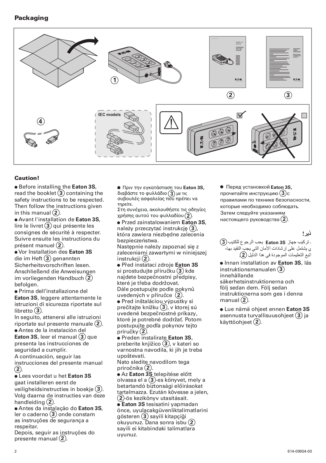
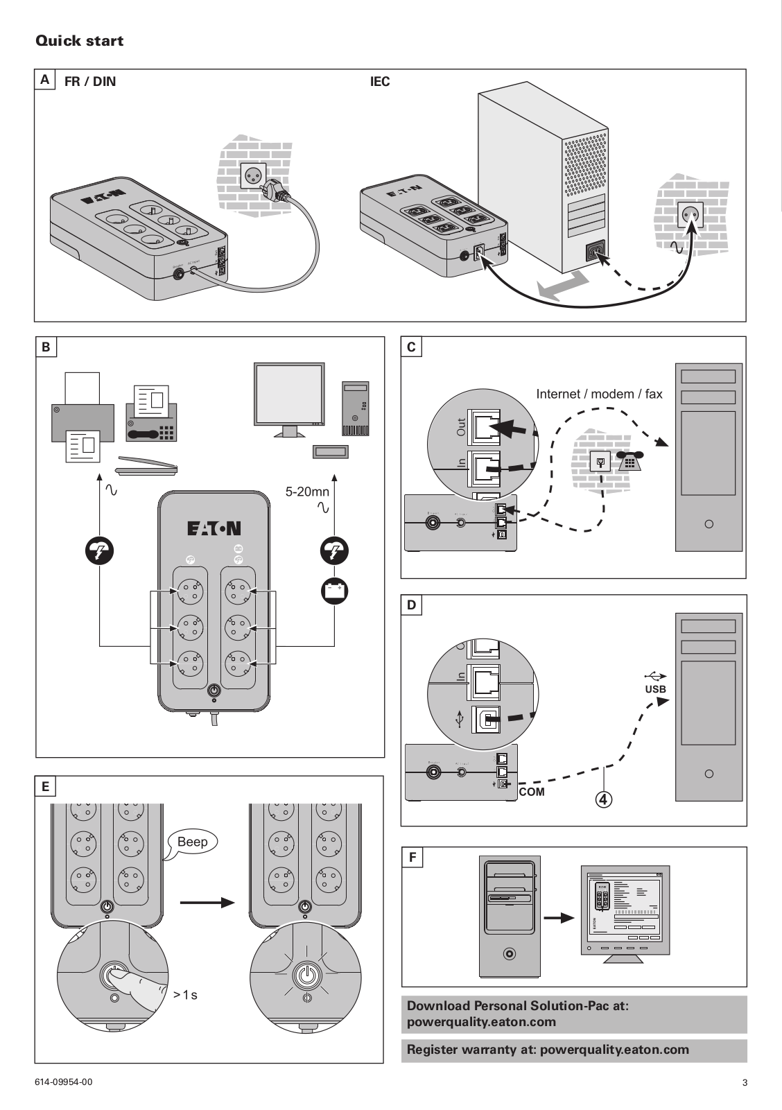
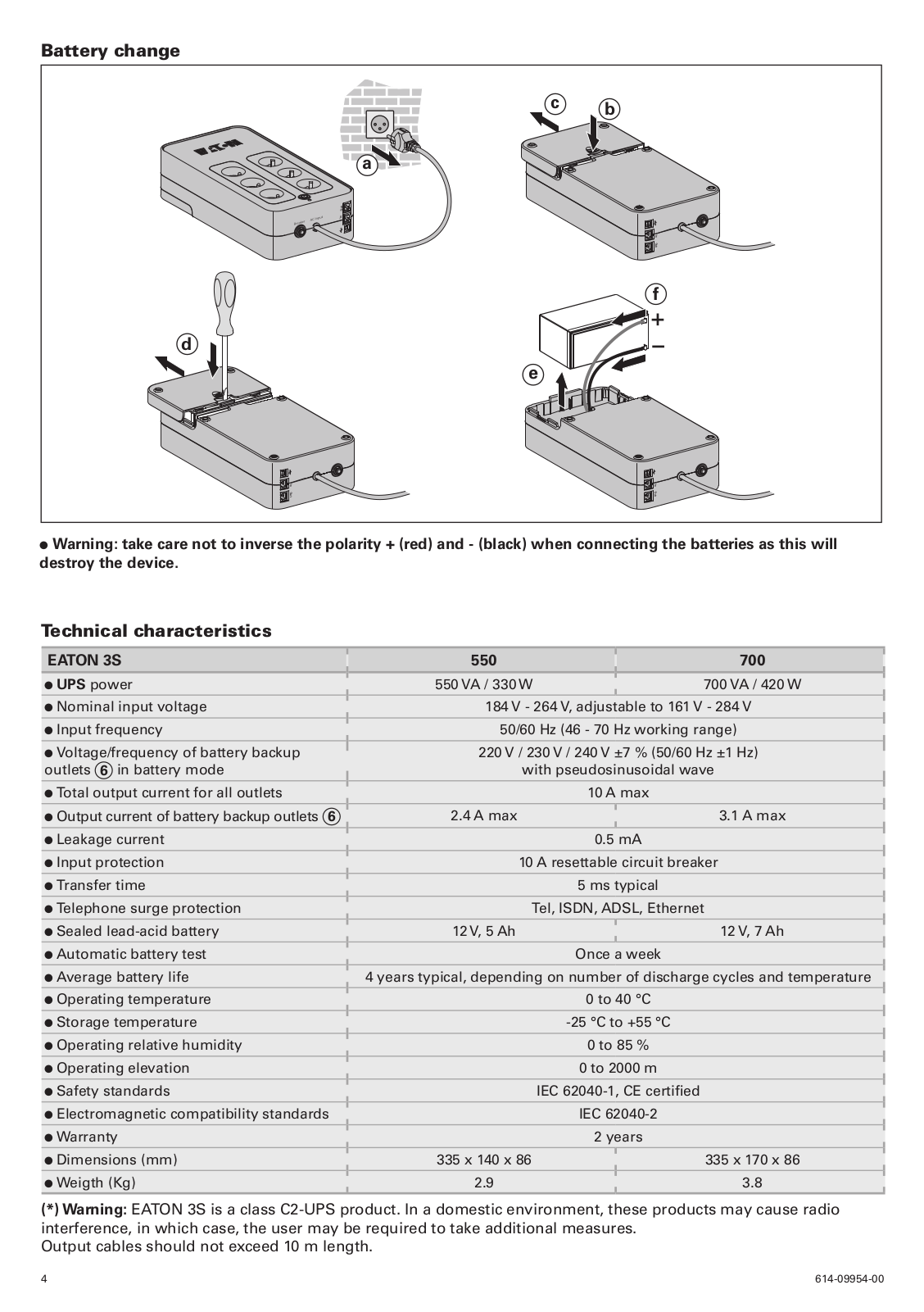
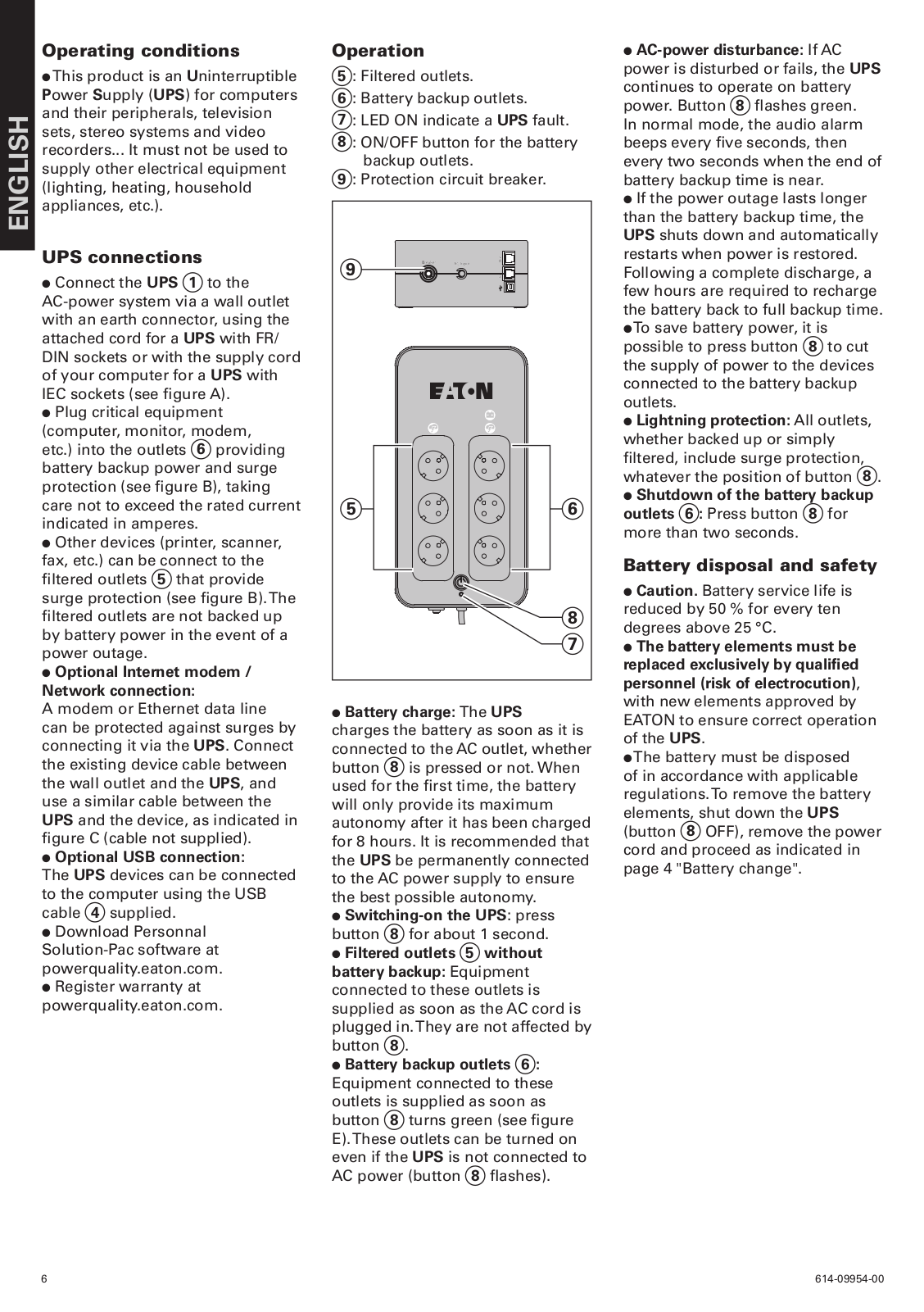
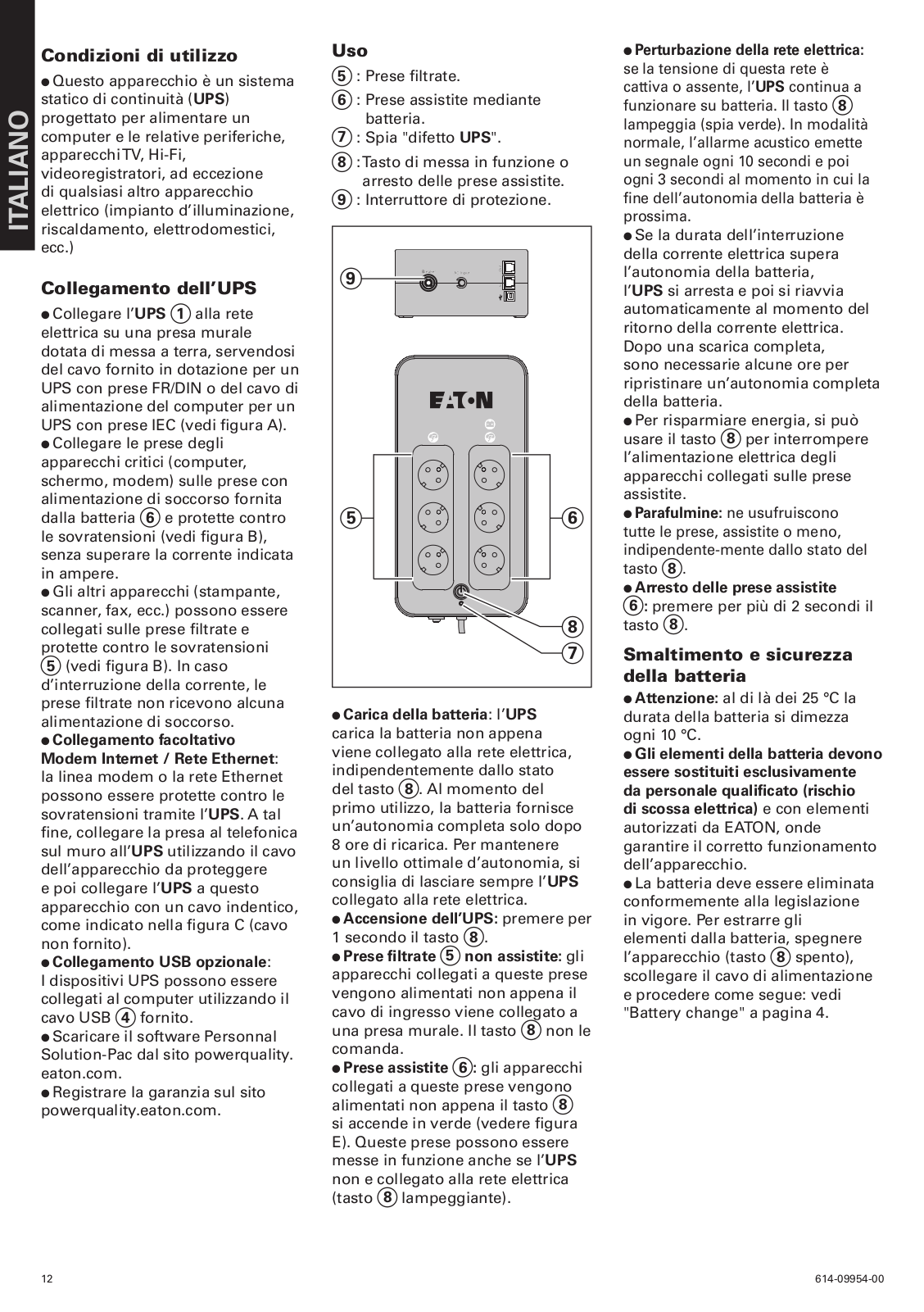
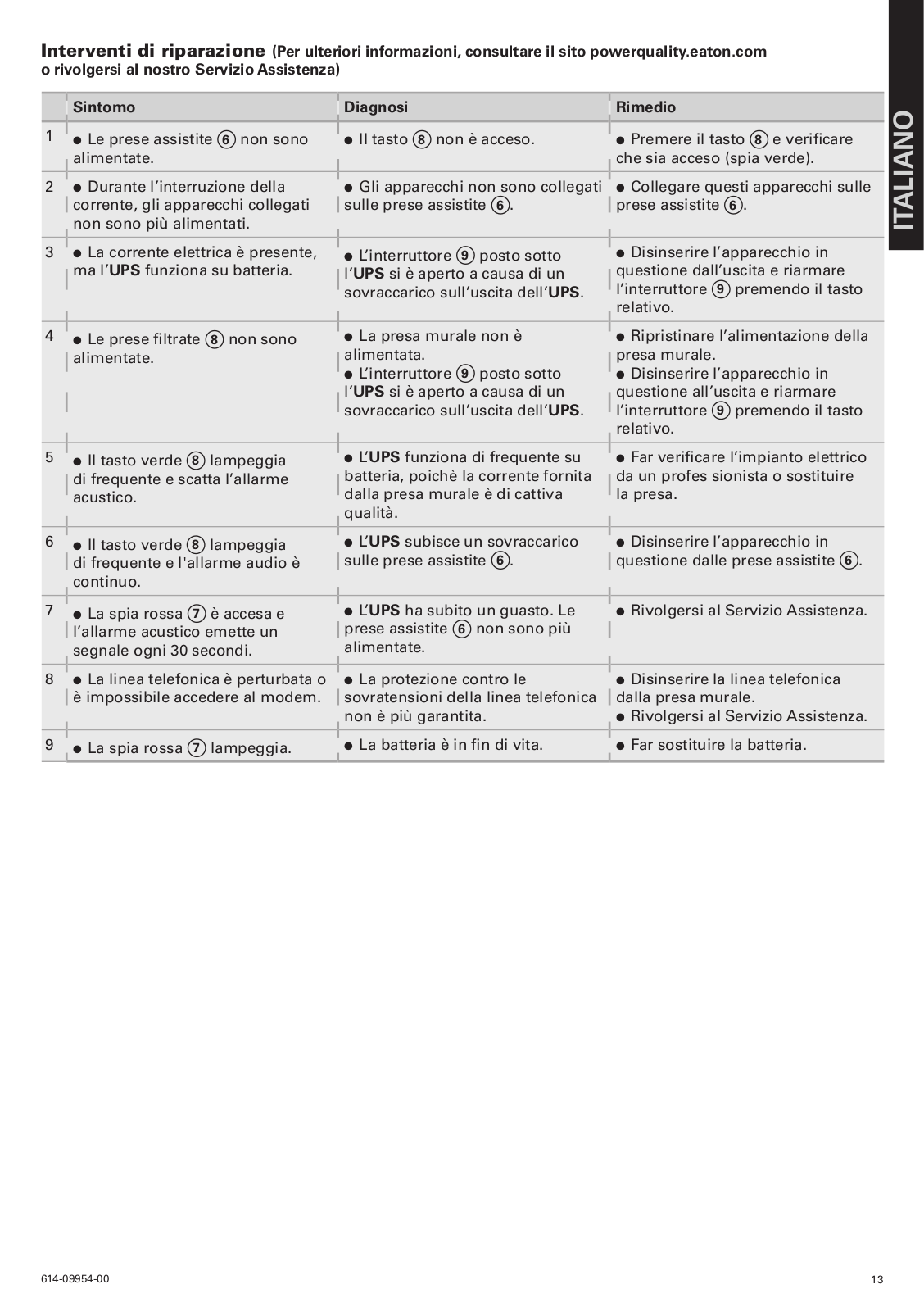
3S
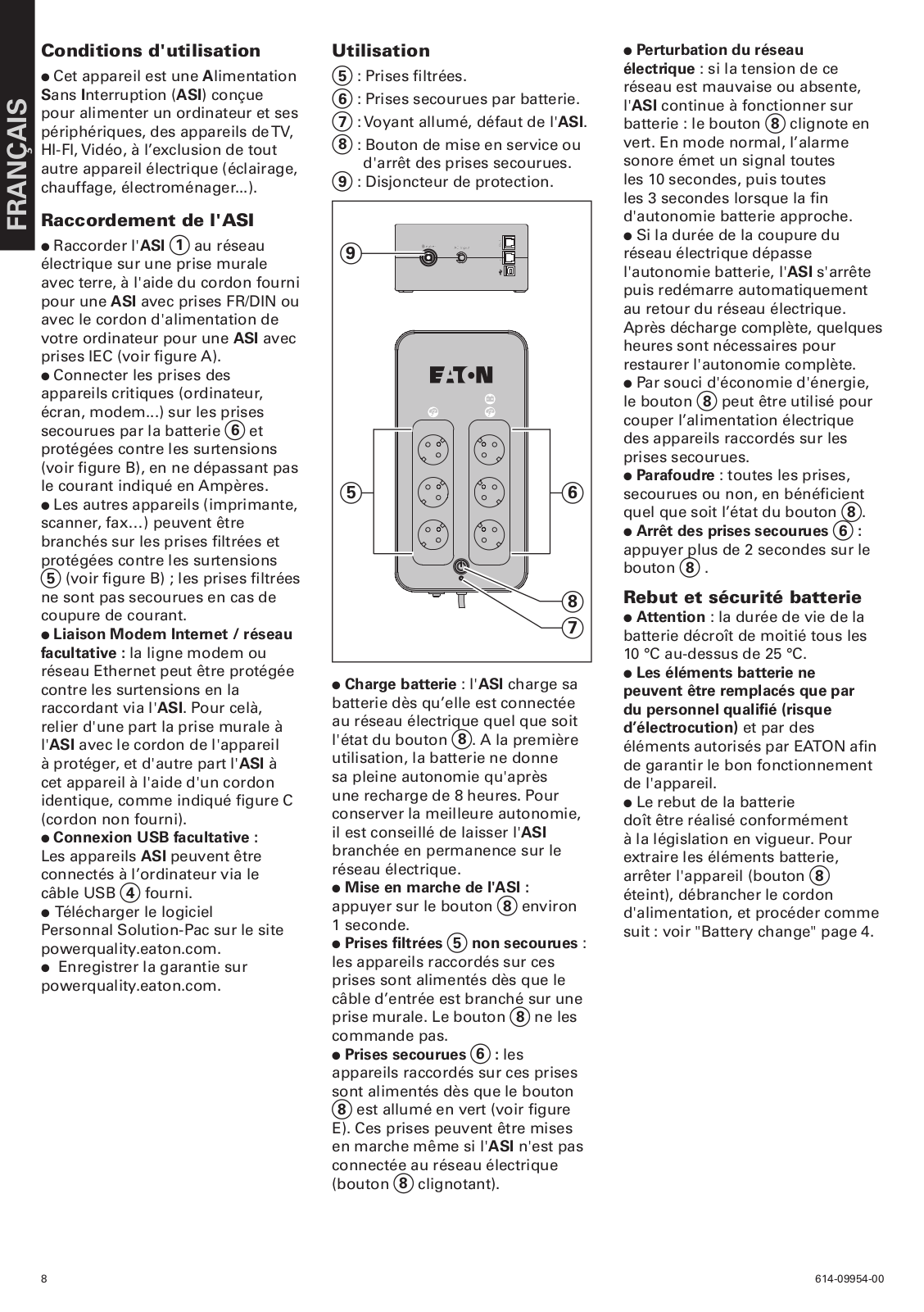
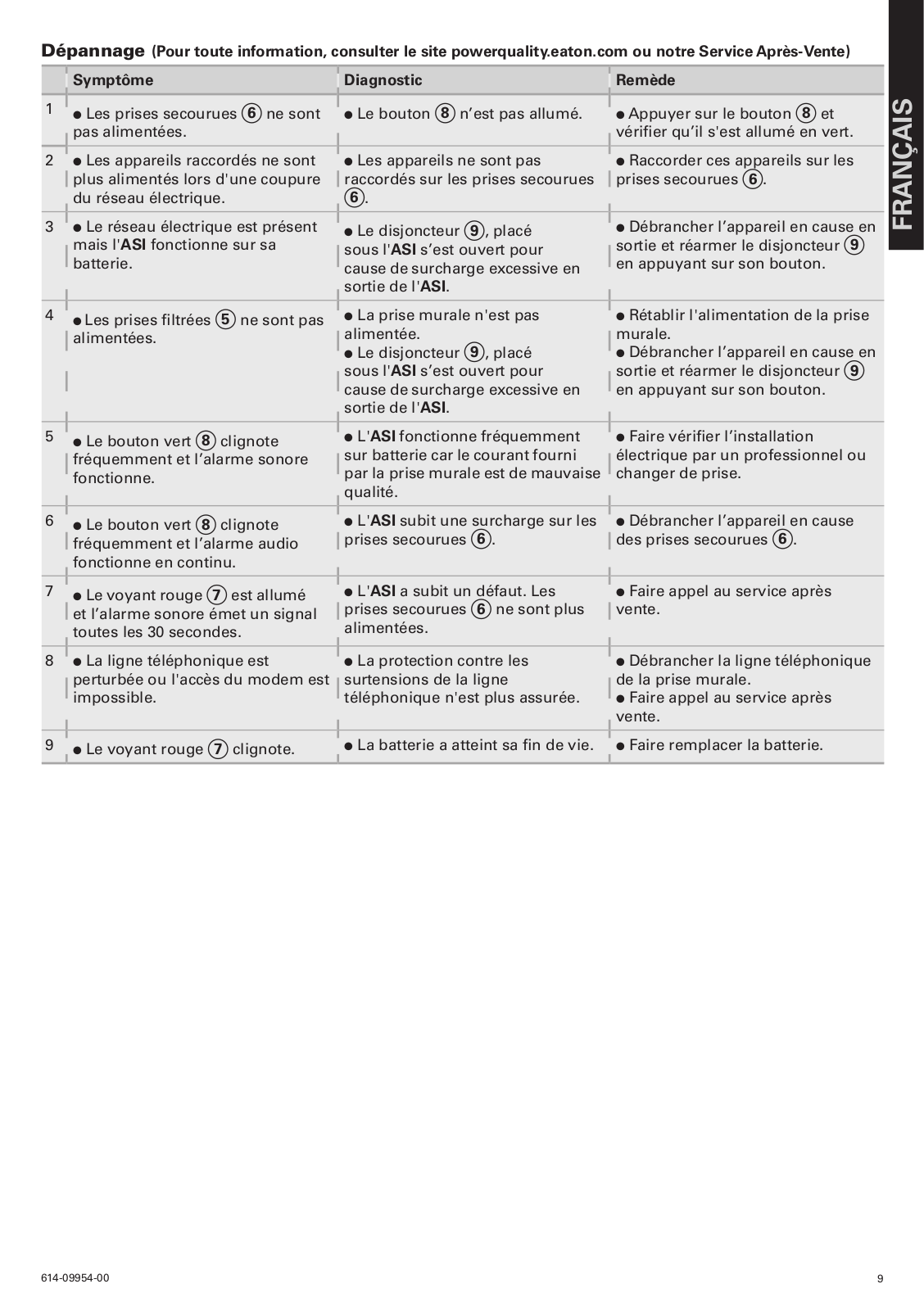
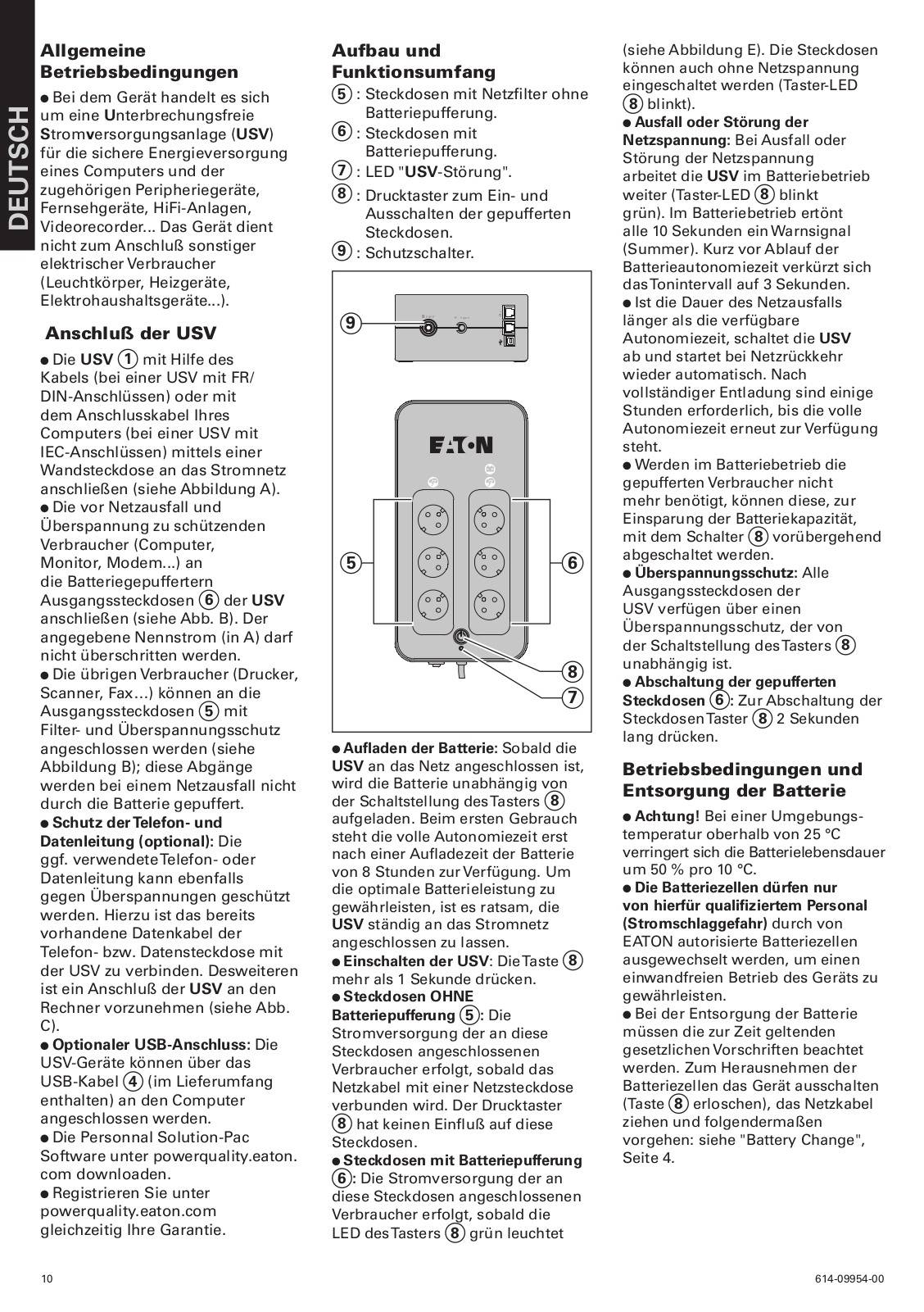
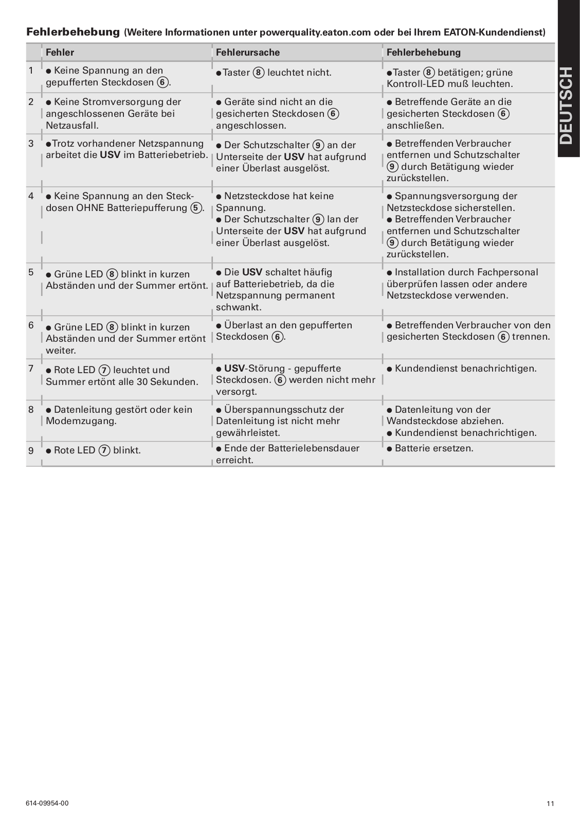
User Manual
42 pgs
6.3 Mb
0
Table of contents
Loading...
EATON 3S User Manual
...
EATON User Manual
Download
Specifications and Main Features
Frequently Asked Questions
User Manual
Download
Loading...
+
29
hidden pages
Unhide
You need points to download manuals.
1 point = 1 manual.
You can buy points or you can get point for every manual you upload.
Buy points
Upload your manuals
 Loading...