

Eastman Ultronic 625 User Manual

INSTRUCTION
BOOK
AND
PARTS
LIST

[Jj}[b1f!X]@[i[)il@
DPERATION
LUBRICATION
Read
AND
this
page before
CARE
operating
this machine
1
®
.
BEFORE
IN
PLEASE KEEP MACHINE
Fill oil
Make
Push in
a few revolutions
mo
sharpener
Use bell
to
Proceed
switch
to
With left
with
to
With right hand
allow
and
This will
to
STARTING
COLD
WEATHER,
cups
A,
B
and
C.
sure
sharpener
turning
ves easily.
is probably
crank
return
sharpener
as
follows:-Check
is
in
off position.
terminal
dis-engage
then
locked position. Knife
block on
hand
fingers
and
sharpener
motor
to
release lever
automatically
is
in
knob F and
by
hand
If
kni
fc
does
in
release lever H (see
to
locked
machine.
straddle
gather
thumb
turn
front
on
full
H.
return
an
Connect
· Press in release lever H
mechanism
motor
WARNIN
F
or
3-phase
must be
on t
urning
3-
phase
machines
as
indicated
knob
F. See tag attached
machines for
IN
WARM PLACE.
locked
posi
turn
the
to
see
if
not
move easily,
unlocke
photo,
position.
to
see
that
attachment
of
sharpener
switch,
speed
sharpener
must
be
in
G
direction
by
arrow
instructions.
tion
.
machine
knife
d position.
at
left)
motor
from
motor.
machine.
of
rotation
to all
over
plug
For
the
first w
eek
or
two, or
machine
the
a few times before allowing
to
This
into
CARE
Use
and sharp
clean
sha
knife slides with
To
do
remove from
TO SHARPEN
Take
Drop
lever R
Press lever E
to
Too
If this occurs, lift lever D
After
correct
has
been
idle for
motor
should
be
run
continuously.
permits
the
air
rpe n
prevent
not
engage sharpening mechanism.
fast lever action may cause lever
the
oil
closely fit moving
OF
MACHI NE
bose
or
bellows
ener
twice a week. Remove cover Q
out
lint
around
er
once
a week. Remove knife
slot
undue accumulation
oil
plate
rollers.
plate
THE
the
machine
pressure foot
located
a few tries
operating
out
next
downward
you
pressure.
turned
to
warm
screw
cleaner
and
KNIFE
of
by
means
to
will feel
any
and
If
rollers stick,
wash
the
machine
with
and
WARNIN
Do
not
operate sharpener
in
machine
will
wh
ile
or the sharpener
be damaged.
sharpener
is
Do
in
after
the
length
of
time,
on
and
off
it
up
and
flow easily
parts.
blow
lint
out
of
mechanism
at
least
in
cleaning solvent.
lay.
of
a slow, firm pressure
start
in
and
once
of
lint,
pressure
operating
to
lock.
over.
clean
a day.
foot
handle.
G
not
shut
motion
without
.
oH
knif
motor
motor
and
e
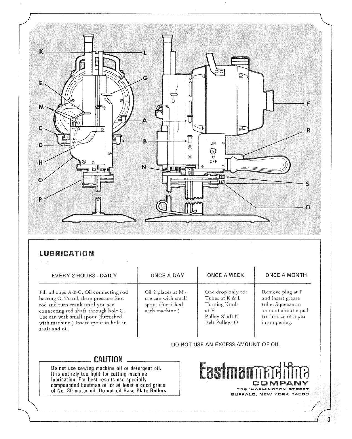
LUBRICATION
EVERY 2 HOURS-
Fill
oil
cups
A-B-C.
bearing
rod
conn
Use can
with
shaft
G.
and
turn
ecting
with
machine
an.d
To
rod
oil.
Oil
oil,
drop
crank
unt
shaft through
small
spout
.)
Insert spout
DAILY
connecting
pressure
il
you
see
hole
(furnished
in
hole
foot
G.
rod
in
ONCE A
Oi] 2 places
use
can
spout (furnished
with
DAY
at
with
sma
machine.)
DO
M -
ll
NOT
ONCE A WEEK
One
Tubes
Tu
at
Pulley
Belt
USE
AN
CAUTION
Do
not
use sewing
It
is
entirely
lubrication.
compounded
of
No
. 30
motor
For
too
machine
light
for
oil
cutting
best results use speci
Eastman
oil.
Do
oil
or
at
not
oil Base Plate
or
detergent
machine
least a
ally
good
oil.
grade
Rollers
~astmanTiTmJ
.
drop
at
rning
F
Shaft
Pull
EXCESS
only
to:
K & L
Knob
N
eys
0
AMOUNT
779
BUFFAL.O, NEW
WASHINGTON
ONCE A
Remove plug
and insert
tube.
amou
to
the
i
nto
OF
Squeeze
nt
about
size
opening.
OIL
MONTH
grease
of a pea
tfnTB
COMPANY
YORK
at
an
equal
STREET
1420:;j
P
3
G!J[17?fXi@[i!Jil@®
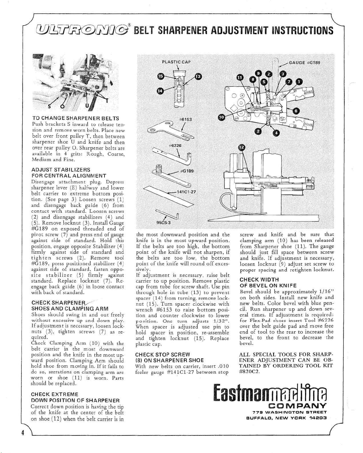
TO
CHANGE
Push
brackets
sion
and
belt
over
sharpener
rear
over
available in 4 gri t
Medium
SHARPENER BELT
S inward
remove worn belts. Place new
front
pulley T, th
shoe U and
pull
ey
0.
and
Fine.
to
knife
Sharpener
s:
Roug
S
release
ten
en
between
and
then
belts are
h, Coarse,
BE
LT
SHARPENER
-
ADJUSTMENT
INSTRUCTIONS
ADJUST ST A
FO
R CENTR
Disengage attachment plug. Depress
sharpener lever
belt carrier
tion
. (See page 3)
and
disengage back guide ( 6)
contact
( 2)
and
(5). Remove l
#G189
p
ivo~
screw
againsc side
position, engage
ftrmly against side
tighten
#G 189, press
against side o standard, fasten opposite
stabilizer
standard. Replace
engage
with back of
CHECK
SHOES
Shoes
without
If
adjustment
nuts
(3), tighten screws (7)
quired.
Check Clamping Arm
belt carrier in the
position
ward position. Clamping Arm
hold
shoe
do
so, s
worn or shoe
should
BILIZERS
AL
ALIGNME
(E) haJ.fway
to
extreme
with
standard.
disengage stabilizers (
ocknut
on exposed
(7) and press end
of
standard.
opposi
screws
/ositione
back
guide (6) in l
standard
SHARPENEfl
AND
CLAMPING
shou
ld swing in
excessive up
is
necess
and
the
kni
from
errations
be rep
moving in.
on
(11)
laced.
bottom
Loosen
Loosen
(
3).
threaded
te Stabilizer ( 4)
of
standard
(2). Remove
d stabilizer ( 4)
(5} firmly against
locknut
.
/ -
and out freely
and
ary
(10)
most
fe
in
clamping
is
NT
and
lower
posi-
screws ( 1)
from
screws
4)
Install Gauge
oose
ARM
down
, loosen lock-
the
If
worn
and
end
of
gauge
Hold
this
and
too
(7). Re-
contact
play.
as
re-
with the
downward
most up-
should
it
fails to
arm
are
. Parts
of
the most
knife
[f
the belts are
point
l
the
poi
nt
sively.
If
adjustmenr
carrier to
cap
from
th
rough
spacer (
nut
(15).
wrench
tion
position.
When spacer
hold spacer in
and
plastic cap.
CHECK ST
(8)
ON
With new belts on
feel
er
downward
is
in the
of
the
knife will
belts
are
of
the
knife will
up
position.
tu be for
hole
in
14
)
from
Turn
#6153
and
cou
nter clockwise
One
is
tighten l
SHARPENER
gauge
OP
#14
ocknut
SCREW
position
most upward
too
hig
too
low,
round
is
necessary , raise belt
screw
tube
(13)
turning, remove
spacer clockwise
to
raise
turn
adjusted
position,
SHOE
carrie
~Cl-
27
and
posi
h, the
not
Remove plastic
adjusts
(
bottom
sharpen,
the
bottom
off
shaft. Use
to
prevent
bottom
to
use pin to
re-assemble
15
).
Re
r, insert .010
between
the
tion
exces-
pin
lock
with
posi-
lower
1/32".
place
stop
screw
.
clamping
from
if
-
Sharpener
should
an
d knife.
loosen
proper spacing and r
CHECK
OF
BEVEL
Bevel should
on
b
oth
new
belts.
cil.
Run
era
l times.
for
Flex-Pad
over
the belt
end of
bevel,
bevel.
ALL SP
ENER ADJUS
TAINED BY ORDE
#82
0C2.
and
knife and be sure th
arm
(10) has
just
locknut
WID
sides. lnstall new knife
sharpener
tool
to
ECIAL
shoe
fill
space
If
adjustment
(9)
TH
ON
KNIFE
be
approximately
Color
If
adjustme
shoes
guide pad
to
the
the
front
TOOLS
TMENT CAN
been
(11). The gauge
between screw
is necessary,
adjust
set
etighten locknut
bevel
with
up and
nt is required:
insert
T
and
rear
to
increase
to
decrease
FOR SHARP-
RING TOOL
released
screw
1/16"
and
blue
pen-
down
sev-
ool
#6226
move free
the
the
BE OB-
KIT
at
to
.
CHECK
DOWN POSITION
Correct
of
on
EXTREME
down
the knife
shoe (
12
OF
position
at
the
center
) when the
SHARPENER
is
having the
of
the belt
belt
carrier
is
fastma
rip
in
4
IITiliT8
COMPAN
775!1
BUFFALO,
WASHINGT
NEW
ON
YC~I(
hiir8
Y
ST'~EET
14203

FOR
BEST
RESULTS
USE
ONLY
EASTMAN
KNIVES
Th
e guarantee
covering
your
Ultronic
St
raight
knife
is
not
valid
if
knives other
than
those
manufactured
by
Eastman
are u
sed
.
KNIFE I TYPE
S
IZE STEEL
Carbon
5"
5"
High Speed
Special Alloy
5"
6"
Carbon
6"
High Speed
6"
High
6"
7"
7"
7"
8"
8"
8"
9"
9"
9"
1
0"
10"
10"
1 1Y."Carbon
11Y." High Speed
1
3"
1
3"
Speed
Special
Alloy
Carbon
Hig
h Speed
Special
Alloy
C"arbon
High Speed
Special
Alloy
Carbon
High Speed
Special
Alloy
Carbon
High Speed
Special
Alloy
Carbon
Hig
h Speed
OF
STRAIGHT
KNIFE
80C5
80C5HS
80C5SA
80C6
80C6HS
80C6SA
80C7
80C.7HS
80C7SA
80C8
80C8HS
80C8SA
80C9
80C9HS
80C9SA
80C 10
80C 1
0HS
80C10SA
80C11Y,
80C
11
Y.HS
80C 13
80C13HS
WAVE
KN
I FE
80C5
-
19
80C5-1
9HS
80C6-19
80C6-19HS
9HS
80C6-1
80C7-
19
80C7-19HS
80C8
-19
80C8-19HS
80C9-19
80C9-
19H
S
80C 10-19
80C10-19HS
%-19HS
80C11
-G*
*-
Grooved
G
Wave
5
v
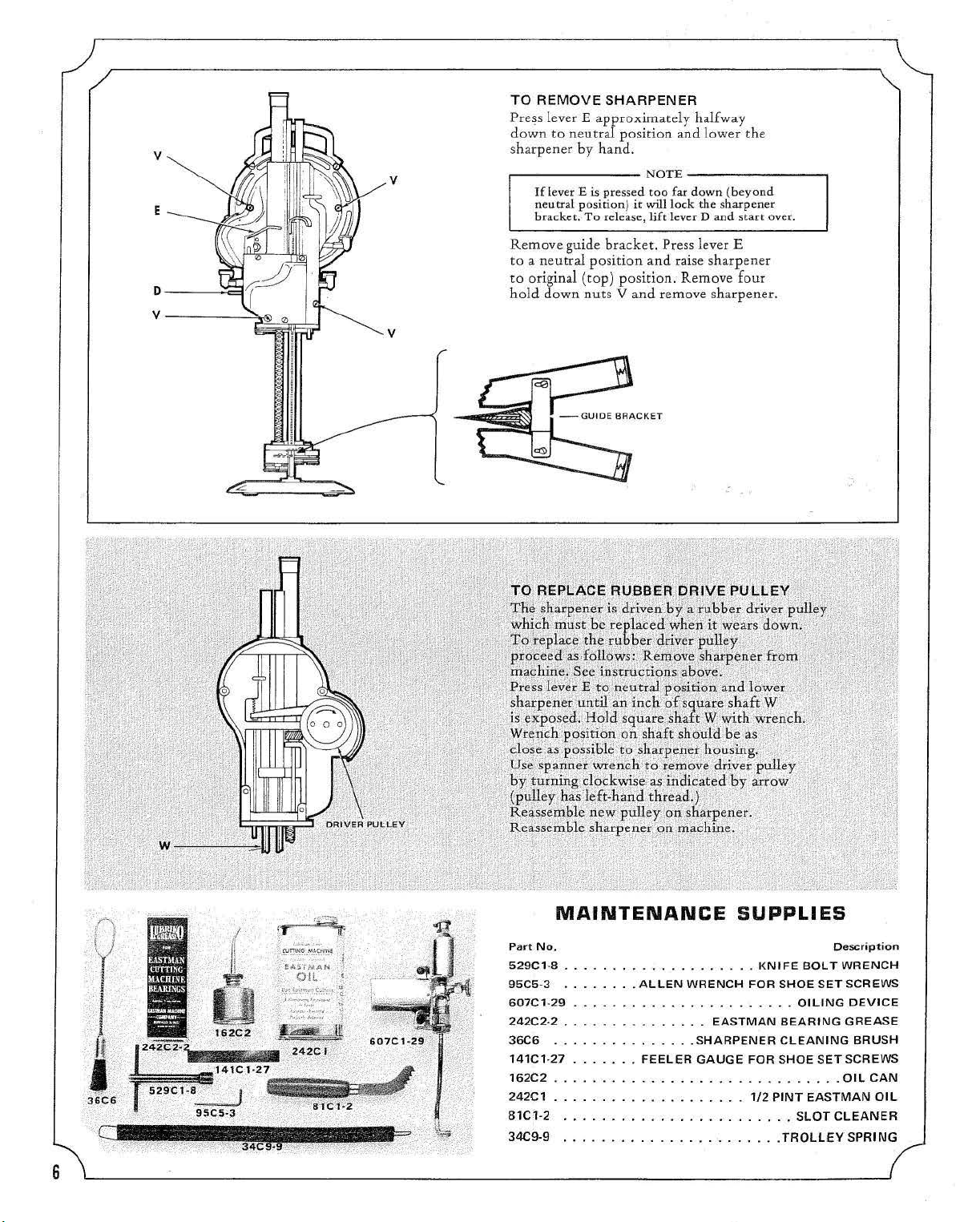
TO REMOVE SHARPENER
Pre~s
lever E
down
approximately
to neutral
sharpener
.--
v
E
----
If
lever
neutral pos
brack
et.
by
E is
To
position
hand.
--
pressed
ition) it
releas
NOTE----------,
will lo
e,
and
too
far
ck
lift lever
halfway
low
er
down
(beyond
the
sharpene
D an d s
the
tart
r
over.
0 -
--
V
--~~
=<:::::t
~
v
Remove guid
to
a n
eutral
to
original
hold
(top)
down
e bracket. Press lever E
position
and
raise sharpener
position. Remove four
nuts V and
remove
sharpener
.
:
MAINTENANCE
Pa
rt No.
529C1·8 ...
95
C5·
3 •
.•.
607C1·
29
242C2
·2 ...
36C6
. .
......
141C1-27
162C2 ......
242C1
81C1
34Cg..9 .......•
. .
....
·2 .•....
6
. .
.
..
.. ..
.
...
.
.......
.
ALLEN
. . . ....
. .
......
.......
FEELER
..........
..•..
...
. . . ..•. .
..
. . . . • . .
SUPPLIES
..
... KNIFE
WRENCH
.....
SHARPENER
GAUGE
....... 1/2
FOR
. .
EASTMAN
FOR
.............
.......
...
. . .
BOLT
SHOE
.•.
OILING
BEARING
CLEANING
SHOE
PINT
EASTMAN
SLOT
TROLL
Descript
WRENCH
SET
SCREWS
DEVICE
GREASE
SET
SCREWS
OIL
CLEANER
EY
SPRING
ion
BRUSH
CAN
OIL
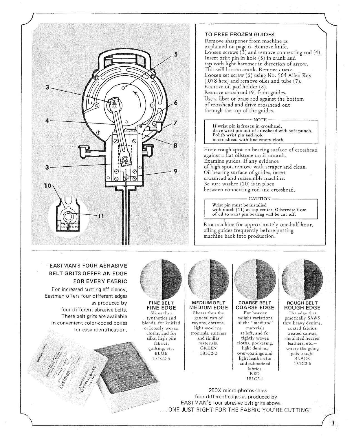
TO
FREE
Remove
sharpener from
explaine d
Loosen
Ins
ta
This
Loosen
ert
drift
p with
wil
screws (3)
light
l
loosen
set
(.978 hex)
Remove oil
FROZEN
on
page 6. Remove knife.
pin
screw
and remov
pad
GUIDES
mac hine
and
remove
in
ho
le ( 5)
in
hammer
in
crank. Re
direction
move
(6) using No. 564
e oil
er
holder
(8).
connecting
crank
crank.
and tube (7) .
Remove crosshead (9) from guides.
Use a fiber
of
crossh
through the
r---
Lf
drive wrist
Po
i.n
or
brass
ead
and
top
----------
wrist
pin
is frozen in
lish WTist
crosshead with
pin
pin
rod
agai
nst
drive crosshead
of
the guides.
--N
OTE
--------------~
cross
out
of
and hole
fme
h e
crosshead
emery cl
the bottom
ad,
with
ot
h.
as
and
of
arrow
Aile~
out
soft punc
rod
K
(4 ).
.
ey
h.
EASTMA
BELT
F
Ea
stman
in conveni
N'S
FOUR
GRITS
or
increased
four different abrasive belts.
These belt grit
offe
FOR
rs f
ent
for
OFFER
EVERY
cutting
our different
as
color-coded boxes
easy identi
ABRASIVE
AN
EDGE
FABRIC
eff
iciency ,
edges
produced
s are
available
fication
by
Hone rough
nst
agai
Examine
of
high
Oil
bearing surface
crosshead
Be su re washer
between
.-------
Wrist
with
of
Run
machine for
oiling guides
machine
.
.
: f.
'
(
FINE
BEL
ces
thru
for
hig
h pile
fabri cs,
BL
UE
T
and
kniti:ed
woven
for
etc.
FI
NE EDGE
Sli
.
synthetics
blends,
or l
.
oosely
cloths, and
silks,
qu
ilting,
181C2-5
MEDIUM BELT
MEDIUM
Shears
general
r
ayons, cott
light
trop
icals
and
m
thru
run
woolens
, suitings
similar
at
erials.
EDGE
GREEN
l81C2
-2
spot
on beari
a flat oilstone
guides.
spot,
If
remove
an
d reassemble machine.
(10) is in p
connect
pin
notch (11) at
oil to
'
ing
must
be installed
wri
st
pin
approximately
freque
back into
the
of
ons
t
,
production
COARSE
COARSE
For
weight
of
the
materials
at
left,
tightly
c
loths, pockering,
light
over-coat
li
ght lcarherette
and
rub
fabrics.
ng
sur
until
face
smooth.
any eyjdence
with
scraper
of guides, insert
]a.ce
rod
and
crosshead .
CAUTION
top
bearing
---------~
cen
ter.
Othe
will
be
cut
one-half
ntly
before
putting
.
BELT
EDGE
heavier
variations
"medium"
and
for
woven
denims,
ings
and
ber
ized
of
crosshead
and
clean.
rwise
flow
off.
ROUGH
ROUGH
The
edge
practically
th
ru
heavy
coated
treated
sim
ulated heav
lea
thers,
where
geis
BLACK
1
81C2
hour,
BELT
EDGE
chat
SAWS
denims,
fab rics,
canvas,
etc
the
going
tough
-6
ier
.-
!
RED
J81C2
-1
250X mic
four
different
EAS
TMAN'S
. . ONE JUST RIGH T
four
abrasive belt
FOR
ro-pho
edges as
THE
FABRIC
tos sh
ow
prod
uced
by
grit
s above .
Y.OU'RE CUTTING'
7
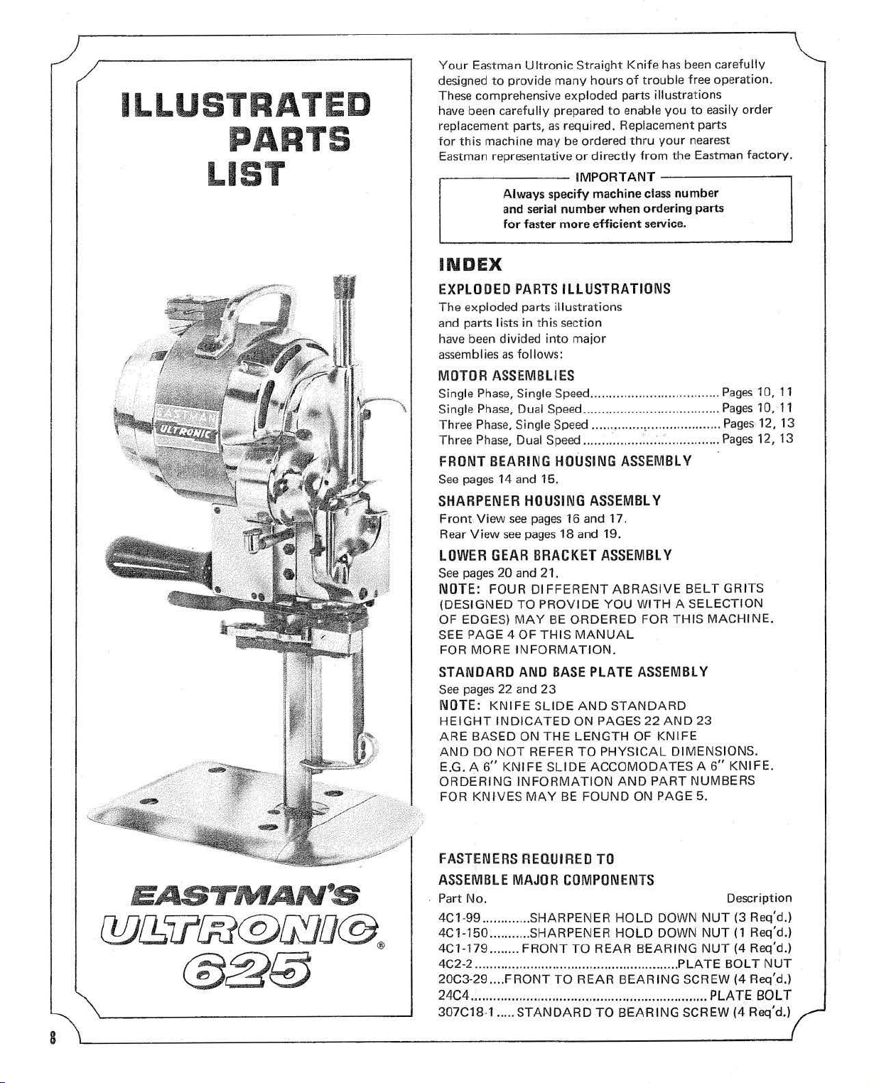
ILLUSTRATED
PARTS
LIST
You
r Eastman
designed
These comprehensive exploded parts illustrations
have been
re
placeme
for
this
Eastman repre
.--------I
Ult
ronic Straight
to
provide
carefully
nt
machine
Always specify machine
and
for
parts,
se
ntat
serial
faster
many
hours
prepared
as
required. Replacement parts
may
be ordered
ive or
directly
MPORTANT---
number
more
efficient
Knif
e has been caref
of
trouble
to
enable
thru
from the Eastman
class
when ordering parts
service.
free operation.
you
to
your
nearest
number
easily order
---
INDEX
EXPLODED
The exploded parts illustrations
and parts lists in
have been divided
assemblies
MOTOR
Single
Single
Three
Th
ree Phase, Dual Speed ................ : ....................
FRONT BEARING
See
pages
SHARPENER
Front
View see
Rear
LOWER
See
pages
NOTE:
(DESIGNED TO PROVIDE
OF EDGES)
SEE
PAGE
FOR
MORE
STANDARD
See
pages
NOTE:
HE
IGHT
ARE
BASED ON THE
AN
D DO
E.G. A
ORDERING
KNIVES
FOR
PARTS
as
follows :
ILLUSTRATIONS
this
section
into
major
ASSEMBLIES
Phase,
Single Speed ...................................
Phase,
Dual Speed ...................................
Phase, Single
14 and 15.
View
see
GEAR
20 and 21.
FOUR Dl
4 OF THIS M
22 and
KNIFE
INDICATED
NOT
6" KNIFE SLIDE
~peed
.............. , .................... Pages 12, 13
HOUSING
HOUSING
pages
pages
BRACKET
FFERENT
MAY
INFORMATION.
AND
23
SLIDE
REFER
INFORMATION
MAY
ASSEMBLY
16 and 17.
18 and 19.
ASSEMBLY
YOU
BE
ORDERED
ANUAL
BASE
PLATE
AND
ON PAGES
LENGTH
TO
PHYSICAL
ACCOMODATES A 6"
BE
FOUND
ASSEMBLY
ABRASIVE
STANDARD
AND
..
BELT GRIT
WITH A SELECTION
FOR T HIS
MACHINE.
ASSEMBLY
22
AND
23
OF
KNIFE
DIMENSIONS
PART
NUMBERS
ON PAGE 5.
ully
fact
Pages
Pages
Pages
KN IFE.
ory.
---..
10,
11
10,
11
12, 13
S
.
FASTENERS
EASTWIAN
C!!Jeb7?1X1@!1!JD@
9
S
®
®:td®
ASSEMBLE
Part
4C1
4C1-150 ...........
4C1
4C2-2 .................................................. .....
20C3·29 ....
No.
-99 ............. SHARPENER HOLD
-179 ........
MAJOR
FRONT
24C4 ...............
307C18-1 .....
8
REQUIRED
COMPONENTS
SHAR
PENER H
FRONT
....
STANDARD
TO
TO
REAR
........................
TO
REAR
BEAR
TO
BEARING
DOWN
OLD
DOWN N
BEARING
ING
......
..........
Description
NUT
(3 Req'd.)
UT
(1
Req'd.)
NUT
(4 R
eq'
PLATE
BOLT
NUT
SCREW (4 Req'd.)
.....
PLATE
SCREW (4 Req'd.)
BOLT
d.)
 Loading...