


 Loading...
Table of Contents
General Safety Precautions........................................ |
3 |
Conveyor Take-On Assembly 68-26138-MS .................. |
34 |
Safety Information ....................................................... |
3 |
Conveyor Drive End Assembly 68-26137-MS ................ |
36 |
Reference Manuals ........................................................ |
4 |
4' Conveyor Extension 68-26152-MS ............................ |
38 |
Recommended Spare Parts List ..................................... |
4 |
Belt Track Assembly 68-26184 ..................................... |
39 |
Software Solutions ......................................................... |
4 |
Vacuum Assembly 68-26139-TL ................................... |
40 |
Safety Zones and Stop Devices ...................................... |
5 |
Rack & Rail Assembly 68-26130-TL ............................. |
42 |
Eagle Conveyor Cutting System Familiarization ............. |
6 |
E-Chain Assembly Part of Conveyor Assembly ............. |
43 |
Computer Control Assembly ........................................... |
7 |
Encoder Assembly 68-26191 (optional) ....................... |
44 |
Gantry Assembly ........................................................... |
8 |
E-stop/Jog Box Assembly 31-26028 ............................. |
45 |
Front Cover Assembly .................................................... |
9 |
Feed S-Roller Assembly SK-04720-MS ........................ |
46 |
Back Cover Assembly .................................................. |
10 |
Static Eliminator Assembly 68-26072-2-MS .................. |
47 |
Control Panel Assembly ................................................ |
11 |
Easi-Hold Assembly 42-26056-MSTL ........................... |
48 |
Front End Plate Assembly ........................................... |
12 |
Out of Cloth Stop Sensor 96-26072 .............................. |
50 |
Back End Plate Assembly ........................................... |
14 |
Out of Cloth Control Module 68-26215 .......................... |
51 |
Main Tube Assembly .................................................... |
16 |
Out of Cloth Probe Assembly 68-26214 ........................ |
51 |
Y-Carriage Assembly .................................................... |
18 |
Press Roller Assembly 9120-896-MS ........................... |
52 |
Tool Head Assembly H9900-3AB .................................. |
20 |
Mini Hold Assembly 68-26240-MS ................................ |
53 |
Optional: Heavy Duty Tool Head Ass'y, H9299-1HDB .... |
22 |
Plastic Overlay Assembly Consult Factory ................... |
54 |
Diagnostic Control Cabinet 31-S3286 .......................... |
24 |
Gantry Pneumatic Diagram 31-9000-19 ........................ |
56 |
Bottom Panel Assembly 68-26105-2 ............................ |
25 |
Belt Tracking Pneumatic Diagram 68-26184-P ............. |
57 |
Rear Panel Assembly 68-26096-2 ................................ |
26 |
Notes ........................................................................... |
58 |
Gantry E-Plate Assembly 68-26094 ............................. |
28 |
Technical Data ............................................................. |
60 |
Conveyor E-Plate Assembly 68-26095-2 ....................... |
30 |
|
|
Eagle Conveyor Assembly 96-26053-MSTL .................. |
32 |
|
|
IMPORTANT
The purchaser must instruct all operators on the proper use of this equipment. All standard industrial safety measures and equipment should be provided to protect the operator. Operators must be cautioned that improper or careless use of this equipment may cause personal injury. If you do not have qualified operators to instruct new persons, contact your EASTMAN sales representative or EASTMAN factory direct.
Electrical connections and servicing to this equipment should be made by a qualified electrician who is familiar with applicable codes and regulations. Disconnect this equipment from electrical power source before proceeding with any disassembly for adjustment or repair.
Your Eastman Eagle Conveyor System is designed to operate at a high rate speed. All personnel should be instructed to wear safety glasses and stand well clear of the Eagle Conveyor System when in operation.
2 |
FormE-532 |

Safety Information
Throughout this manual, safety information is presented by the use of the terms WARNING, CAUTION, ELECTRICAL HAZARD, and NOTE. These terms have the following meanings:
 WARNING
A warning contains critical information regarding potential safety hazards that can occur during proper use or misuse of the machine. Failure to follow these procedures may result in serious personal injury to the user.
 CAUTION
A caution contains instructions for the use or maintenance of the machine. Failure to follow these procedures may result in damage to the machine.

 ELECTRICAL HAZARD
An electrical hazard calls attention to a procedure, practice, or the like, which, if not correctly performed or adhered to, could result in personal injury. Do not proceed beyond an Electrical Hazard.
Supplementary information may be given in a Note.
General Safety Precautions
 WARNING
•This machine is equipped with very sharp and dangerous tools. Keep hands, arms, and hair away from the cutting area and drive system at all times. Safety gloves, glasses, and appropriate clothing may prevent serious personal injuries.
•Disconnect the power supply to the machine when it is not in use or during routine maintenance, including cleaning and lubrication.
•The purchaser must instruct all operators in the proper use of the machine according to the instructions in this manual. This training must include instruction on the potential safety hazards arising from the use or misuse of the machine. In addition to such training, the purchaser should provide written work instructions as necessary to ensure correct use of the machine for specific cutting and spreading applications.
Safety and Indemnification
During the life of the machine, the purchaser agrees to provide to all machine users (including its own employees and independent contractors) all relevant safety information, including warning labels and instruction manuals. The purchaser also agrees to maintain the safety features and working condition of the machine, and to adequately train all users in the safe use and maintenance of the machine. The purchaser agrees to defend, protect, indemnify, and hold Eastman Machine Company and its subsidiaries harmless from and against all claims, losses, expenses, damages, and liabilities to the extent that they have been caused by the purchaser’s failure to comply with the terms and instructions of this manual.
•Do not modify this machine or disable safety features. Unauthorized modification may result in serious personal injuries to the user. Electrical connections to this machine must be made by a qualified electrician familiar with applicable codes and regulations.
•Safety labels must be kept clean and legible at all times. Call the Eastman Machine factory to order replacement labels.
FormE-532 |
3 |

The Eastman Eagle Conveyor Automated Cutting machine has been inspected and tested at the factory prior to shipment. The Eagle Conveyor machine is shipped partially disassembled and requires some assembly and setup before operation can take place. Refer to the installation guide for installation instructions. To get the best performance, familiarize yourself and all operators with all functions and adjustments of this equipment. Refer to the Eagle Conveyor service manual. Before any operation takes place it is important carefully read and follow the instructions in these reference manuals.
This Illustrated Parts List is a comprehensive list of the components used in the machine. When ordering replacement parts, please include machine name and serial number. Some machine configuration may require additional components not shown, please consult factory for part numbers.
The following list of recommended spare parts and reference manuals may be included with your machine or purchased at a later date.
Reference Manuals
E-536 ............ |
Eagle-C Instruction and Service Manual |
E-534 ............ |
Eagle-C Illustrated Parts List |
E-515 ............ |
Automated Cutting Tools Illustrated Parts |
|
Manual |
E-521-2.1 ...... |
Easicut 2 Software Manual |
E-522 ............ |
Air Brush Marking System Manual |
E-535 ............ |
Touch Screen Software Install guide |
Recommended Spare Parts List Part Number Description
10-00900-2 ... Computer Multifunction Board
31-03002 ...... Motion Control Board, MEI
31-B2005 ..... X1-Axis Motor
31-B2000 ..... X2-Axis Motor
31-S3205-1 .. Y-Axis Motor
31-03012-2 ... Motor Amplifiers, Quantity of 2 54-26295 ...... X-Axis Spur Gear, Quantity of 2 31-12660-15 . 5 vdc Power Supply 31-12660-16 . 12 vdc Power Supply 54-D0066 ..... X-Axis Motor Pulley
67-12983 ...... X-Axis Linear Bearing, Quantity of 2
Consult Factory |
Replacement Cutting Surface |
See E-515 Manual |
Replacement Pen |
See E-515 Manual |
Replacement Cutting Tools |
Software Solutions
Eastman offers a wide variety of software to solve even the most difficult tasks.
Please consult your nearest Eastman Representative or the Eastman Factory direct for more information.
4 |
FormE-532 |
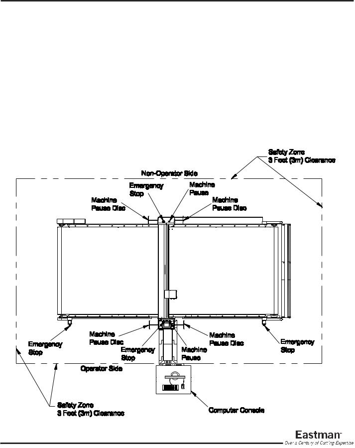
Safety Zones and Stop Devices
Pause Buttons/Disc
The yellow buttons above the control panel and on the non-operator side of the gantry as well as the pause discs on each side of the gantry will pause the machine. Activating either the button or the pause disc will execute a controlled stop of the plotter, with the machine remaining fully powered. After releasing the pause button or resetting the pause discs and pressing NEXT on the UIT keypad, the cutter will resume cutting the work in progress. Pressing ABORT will cancel the job.
Emergency Stop Buttons
There are red Emergency Stop buttons located on each side of the gantry as well as on the operator side right and left ends of the table. Pressing any of the Emergency Stop buttons will execute a controlled stop of the gantry before cutting all power to the motors and e-box. To release an Emergency Stop condition, pull out the Stop button hit the ABORT key on the UIT keypad. The table must be re-homed by pressing the ZERO TABLE button before restarting the cutter. Emergency stop mats are also available as an option.
FormE-532 |
5 |

Eagle Conveyor Cutting System
Familiarization
6 |
FormE-532 |

Computer Control
Assembly
|
|
Software Solutions |
|
ITEM PART No. |
DESCRIPTION |
QTY |
||
|
Eastman offers a wide variety of software to solve |
|
1 |
31-S3286 |
Diagnostic E-box Cabinet |
1 |
||
|
even the most difficult tasks. Please consult your |
|
|
96-26083-220 |
220 volt, Voltage Connection Kit |
* |
||
|
nearest Eastman Representative or the Eastman |
|
|
96-26093-480 |
480 volt, Voltage Connection Kit |
* |
||
|
Factory direct for more information. |
2 |
10-26063 |
15" Color Flat Panel Monitor |
* |
|||
|
|
|
|
|
10-26064 |
17" Color Flat Panel Monitor |
1 |
|
|
|
|
|
|
||||
|
|
|
|
|
10-26065 |
19" Color Flat Panel Monitor |
* |
|
|
|
|
|
3 |
11-00868-02 |
Computer Keyboard |
1 |
|
|
|
|
|
4 |
11-00054-1 |
Computer Mouse, Unshielded |
1 |
|
|
Computer Internal Component Kit |
|||||||
|
|
* |
11-00054 |
Computer Mouse, Shielded |
1 |
|||
|
10-00900-2A |
Multifunction Board |
|
5 |
10-26002-ce-ind Industrial Computer |
1 |
||
|
31-S1009 |
MEI to Multifunction Cable |
6 |
31-270013 |
RS232/RS422 Serial Data Converter1 |
|||
|
31-S1017 |
I/O Bracket |
7 |
31-S9009 |
Computer Internal Component Kit |
1 |
||
|
91-26034 |
Computer Labels |
|
* Optional |
|
|
|
|
|
31-03002 |
Motion Control Board, MEI |
|
|
|
|
|
|
|
68C3-16 |
Rubber Foot |
|
|
|
|
|
|
|
31-26032 |
PC Harness |
|
|
|
|
|
|
|
|
|
|
|
|
|
|
|
|
|
|
|
|
|
|
|
|
FormE-532 |
7 |

Gantry Assembly
68-26132-MS
Note: MSMachine Size
|
ITEM |
PART No. |
DESCRIPTION |
QTY |
|
1 |
409-99-1 |
Finish Washer |
A/R |
|
2 |
333-93-8S |
Screw, Cover |
A/R |
|
3 |
335-93-8 |
Screw, Socket #8-32 x 1/2 |
4 |
|
4 |
410-080 |
Washer, Flat #8 |
12 |
|
5 |
335-93-10 |
Screw, Socket #8-32 x 5/8 |
12 |
|
6 |
410-010 |
Washer, Flat #10 |
6 |
|
7 |
402-010 |
Washer, Lock #10 |
6 |
|
8 |
335-102-10 |
Screw, Socket #10-32 x 5/8 |
6 |
|
|
|
|
|
|
|
|
|
|
8 |
FormE-532 |

Front Cover Assembly
68-26115
ITEM PART No. |
DESCRIPTION |
QTY |
1333-34-12z Screw, Button Hd. 1/4-20 x 3/4 2
2 |
54-26419 |
Stop Disk |
2 |
3 |
54-26420 |
Rod, Stop Disk |
1 |
4 |
333-102-8 |
Screw, Button Hd. 10-32 x 1/2 |
6 |
5 |
54-26423 |
End Cap |
2 |
6 |
91-26002-W |
Decal, Small Eastman, White |
1 |
7 |
91-26031-W |
Decal, Eagle, White |
1 |
8 |
54-26623 |
Operator Side Cover |
1 |
9 |
67-26311 |
Slide Bearing |
2 |
10 |
54-26421 |
Bearing Mount |
1 |
11 |
318-93-6 |
Screw, Pan Head #8-32 x 3/8 |
2 |
12 |
404-080 |
Lock Washer, #8 Internal |
2 |
13 |
54-26426 |
Switch Bracket |
1 |
14 |
11-1193 |
limit Switch |
1 |
15 |
404-040 |
Lock Washer, #4 External |
2 |
16 |
313-81-8 |
Screw, Round Hd. #4-40 x 1/2 |
2 |
17 |
54-26422 |
Bearing & Switch Mount |
1 |
18 |
9078-003 |
Spring Plunger, 3/8-16 |
1 |
19 |
205-38 |
Hex Nut, 3/8-16 |
1 |
|
|
|
|
Stop Disk
Wiring Harness 31-S3338
Not Shown
FormE-532 |
9 |
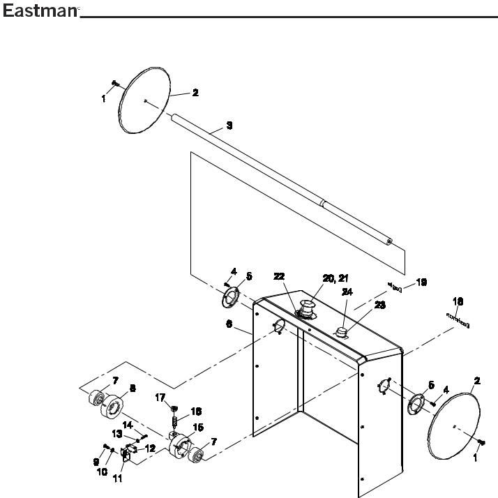
Back Cover Assembly
68-26116
ITEM |
PART No. |
DESCRIPTION |
QTY |
12 |
11-1193 |
limit Switch |
1 |
13 |
404-040 |
Lock Washer, #4 External |
2 |
14 |
313-81-8 |
Screw, Round Hd. #4-40 x 1/2 |
2 |
15 |
54-26422 |
Bearing & Switch Mount |
1 |
16 |
9078-003 |
Spring Plunger, 3/8-16 |
1 |
17 |
205-38 |
Hex Nut, 3/8-16 |
1 |
18 |
91-26002-W |
Decal, Small Eastman, White |
1 |
19 |
91-21031-W |
Decal, Eagle Logo, White |
1 |
|
|
|
|
ITEM |
PART No. |
DESCRIPTION |
QTY |
|
|
|
|
|
1 |
333-34-12Z |
Screw, Button Hd. 1/4-20 x3/4 |
2 |
|
|
|
|
|
2 |
54-26419 |
Stop Disk |
2 |
|
ITEM |
PART No. |
DESCRIPTION |
QTY |
3 |
54-26420 |
Rod, Stop Disk |
1 |
|
||||
|
20 |
31-26012-3 |
Mushroom Switch, Red |
1 |
||||
4 |
333-102-8 |
Screw, Button Hd. 10-32 x 1/2 |
6 |
|
||||
|
21 |
31-26033 |
Lamp, 12 vdc |
1 |
||||
5 |
54-26423 |
End Cap |
2 |
|
||||
|
22 |
91-26011-1 |
Decal, Yellow Emergency Stop 1 |
|||||
6 |
54-26624 |
Non-Operator Side Cover |
1 |
|
||||
|
23 |
31-26307 |
Push Button/ Contact, Yellow |
1 |
||||
7 |
67-26311 |
Slide Bearing |
2 |
|
||||
|
24 |
91-26041 |
Decal, Machine Pause |
1 |
||||
8 |
54-26421 |
Bearing Mount |
1 |
|
||||
|
|
|
|
|
||||
9 |
318-93-6 |
Screw, Pan Head #8-32 x 3/8 |
2 |
|
|
|
|
|
10 |
404-080 |
Lock Washer, #8 Internal |
2 |
|
|
|
|
|
11 |
54-26426 |
Switch Bracket |
1 |
|
|
|
|
|
|
|
|
|
|
|
|
|
|
10 |
FormE-532 |
Control Panel Assembly
UIT Software Installation Guide
The UIT Software is installed at the factory. Refer to UIT Software Installation Guide E-535.
ITEM |
PART No. |
DESCRIPTION |
QTY |
1 |
31-26304-1 |
Touch Screen Control Panel |
1 |
|
79-26001 |
Key Label (included in 31-26304-1)1 |
|
|
02-00074 |
Control Panel Program |
1 |
2 |
333-93-8 |
Screw, Button Hd #8-32 x 1/2 |
6 |
3 |
91- |
Decal, On/OFF |
1 |
4 |
31-26331 |
Green Selector Switch |
1 |
5 |
31-26012-3 |
Red Mushroom Switch |
1 |
6 |
91-26011-2 |
Yellow Stop Ring |
1 |
7 |
31-26307 |
Yellow Push Button Switch |
1 |
8 |
91-26041 |
Decal, Button Labels |
1 |
9 |
54-26596 |
Control Panel |
1 |
10 |
67-26465 |
Hole Plug |
2 |
11 |
54-26595 |
Right Support, Panel |
1 |
12 |
54-26594 |
Left Support, Panel |
|
13 |
31-26033 |
Mini Light Bulb |
3 |
FormE-532 |
11 |

Front End Plate Assembly
68-26117
12 |
FormE-532 |

ITEM |
PART No. |
DESCRIPTION |
QTY |
|
1 |
-------------- |
Control Panel Assembly |
|
1 |
2 |
333-86-4 |
Screw, Button Hd. #6-32 x 1/4 |
|
2 |
3 |
11-919 |
Ground Terminal |
|
1 |
4 |
54-26598-1 |
Spacer, Shock Mount |
|
1 |
5 |
67-26402 |
Shock Absorber |
|
1 |
6 |
335-93-16 |
Screw, Socket Hd. #8-32 x 1 |
|
1 |
7 |
342-93-4 |
Setscrew, #8-32 x 1/4 |
|
2 |
8 |
54-D0066 |
Motor Pulley |
|
1 |
9 |
** |
Key, part of motor assembly |
|
1 |
10 |
54-26019 |
Motor Mounting Plate |
|
1 |
10A |
31-B2005 |
X1-Axis Motor with Harness |
|
1 |
11 |
335-93-8 |
Screw, Socket Hd. #8-32 x 1/2 |
4 |
|
12 |
54-LC095 |
Bearing Spacer Shim |
|
1 |
13 |
67-12984 |
Bearing |
|
2 |
14 |
54-D0019 |
Bearing Housing |
|
2 |
15 |
9063-104 |
Key, .188 x .188 x .859 |
|
1 |
16 |
54-D0276 |
Drive Shaft |
|
1 |
17 |
9063-010 |
Key, .188 x .188 x .734 |
|
1 |
18 |
54-26295 |
Spur Gear |
|
1 |
19 |
342-102-5 |
Setscrew #10-32 x 5/16 |
|
2 |
20 |
335-35-24 |
Screw, Socket 1/4-28 x 1 1/2 |
|
2 |
21 |
54-LC098 |
Backlash Adjuster |
|
2 |
22 |
67-12983 |
Linear Bearing |
|
2 |
23 |
54-26603 |
Support, Bearing |
|
2 |
24 |
341-4-12 |
Screw, Socket m4 x 12mm |
|
8 |
25 |
333-86-8 |
Screw, Socket Hd. #6-32 x 1/2 |
4 |
|
26 |
335-93-8 |
Screw, Socket Hd. #8-32 x 1/2 18 |
||
27 |
54-C0306 |
Cover Mounts |
|
6 |
28 |
11-1940 |
Spacer, 7/16 Long |
|
4 |
29 |
31-26012-15 |
Power Supply, 5vdc |
|
1 |
30 |
11-1981 |
Spacer, 1-1/8 Long |
|
8 |
|
|
|
|
|
|
ITEM |
PART No. |
DESCRIPTION |
QTY |
|
|
|
31 |
31-26012-16 |
Power Supply, 12vdc |
|
1 |
|
|
32 |
54-26025 |
Power Supply Shield |
|
1 |
|
|
33 |
404-060 |
Star Lock Washer |
|
4 |
|
|
34 |
333-86-6 |
Screw, Socket Hd. #6-32 x 3/8 |
4 |
|
|
35 |
54-D0485 |
Drive Standoff Plate |
|
2 |
|
|
36 |
54-D0022-2 |
Shaft Support |
|
1 |
|
|
|
37 |
335-93-8 |
Screw, Socket Hd. #8-32 x 1/2 |
6 |
|
|
|
38 |
67-D0216-5 |
Snap Ring |
|
4 |
|
|
39 |
332-102-10 |
Screw, Flat Hd. #10-32 x 5/8 |
|
8 |
|
|
40 |
67-02963-1 |
Drive Belt,htd |
|
1 |
|
41 |
54-D0065 |
Pulley, Large |
|
1 |
|
|
42 |
342-93-4 |
Setscrew, #8-32 x 1/4 |
|
2 |
|
|
|
43 |
335-102-10 |
Screw, Flat Hd. #10-32 x 5/8 |
|
8 |
|
|
44 |
402-010 |
Lock Washer #10 |
|
8 |
|
|
45 |
410-010 |
Flat Washer #10 |
|
8 |
|
|
46 |
335-102-10 |
Screw, Socket #10-32 x 5/8 |
|
8 |
|
47 |
332-102-20 |
Screw, Flat Hd. #10-32 x 1 1/4 |
|
8 |
|
|
48 |
410-34 |
Flat Washer, 1/4 |
|
2 |
|
|
49 |
402-34 |
Lock Washer, 1/4 |
|
4 |
|
|
50 |
333-34-20 |
Screw, Button 1/4-20 x 1 1/4 |
|
2 |
|
|
51 |
335-34-20 |
Screw, Socket 1/4-20 x 1 1/4 |
|
2 |
|
|
*52 |
31-00922 |
Roller Switch, 90 degree spdt |
|
2 |
|
|
53 |
54-26554 |
Operator Side Plate, Right |
|
1 |
|
|
*54 |
335-86-4 |
Screw, Socket #6-32 x 1/4 |
|
4 |
|
|
*55 |
54-26224 |
E-chain Funnel |
|
2 |
|
|
56 |
91-26026 |
Decal, 2 amp, 120 volt |
|
1 |
|
|
* Not included in assembly A/R -As Required
FormE-532 |
13 |

Back End Plate Assembly
68-26118
Switch Cable Kit (96-26073) Not Shown
31-S3002-X2H |
Gantry Switch Assembly, X2 Home |
31-S3002-XL |
Gantry Switch Assembly, X Limit |
31-S3002-YL2 |
Gantry Switch Assembly, Y Limit |
|
|
14 |
FormE-532 |

ITEM |
PART No. |
DESCRIPTION |
QTY |
ITEM |
PART No. |
DESCRIPTION |
QTY |
|||||
|
|
1 |
** |
Key, part of motor assembly |
1 |
|
38 |
31-S3315-MS |
RS422 Cable |
|
1* |
|
|
|
2 |
54-26019 |
Motor Mounting Plate |
1 |
|
39 |
67-01005 |
Locking Screw Kit (part of) |
|
1 |
|
|
|
3 |
31-B2000 |
X2-Axis Motor with Harness |
1 |
|
40 |
67-01005 |
Locking Screw Kit (part of) |
|
1 |
|
|
|
4 |
342-93-4 |
Setscrew, #8-32 x 1/4 |
2 |
|
41 |
31-00972 |
8-Pin Connector, Large (only) |
|
1 |
|
5 |
54-D0066 |
Motor Pulley |
1 |
|
|
31-02973 |
Strain Relief |
|
1 |
|||
6 |
333-86-4 |
Screw, Button Hd. #6-32 x 1/4 |
2 |
|
|
31-12929 |
10mm Boot |
|
1 |
|||
|
|
7 |
335-93-16 |
Screw, Socket Hd. #8-32 x 1 |
1 |
|
|
31-12930 |
12mm Boot |
|
1 |
|
|
|
8 |
67-26402 |
Shock Absorber |
1 |
|
42 |
335-93-10 |
Screw, Socket Hd. #8-32 x 5/8 4* |
|||
|
|
9 |
100-13-2 |
Elbow 1/4 NPT x 1/4" |
2 |
|
43 |
54-26693 |
E-Chain Mount |
|
1* |
|
|
|
10 |
27-20001 |
Air Control Regulator |
1 |
|
44 |
54-26694 |
E-Chain Side Mount |
|
2* |
|
|
|
|
31-00952 |
MTE Connector |
1 |
|
45 |
342-93-4 |
Setscrew, #8-32 x 1/4 |
|
2 |
|
|
|
|
31-00960 |
MTE Receptacle Pin |
3 |
|
46 |
332-102-20 |
Screw, Flat Hd. #10-32 x 1 1/4 |
|
8 |
|
|
|
11 |
203-93 |
Nut, Hex #8-32 |
4 |
|
47 |
335-102-10 |
Screw, Socket #10-32 x 5/8 |
|
8 |
|
|
|
|
404-080 |
Washer, Locking #8 |
4 |
|
48 |
402-010 |
Lock Washer #10 |
|
8 |
|
|
|
12 |
335-93-8 |
Screw, Socket Hd. #8-32 x 1/2 18 |
|
49 |
335-102-10 |
Screw, Socket #10-32 x 5/8 |
|
8 |
||
|
|
13 |
54-26555 |
Side Plate, Non-Operator |
1 |
|
50 |
410-010 |
Flat Washer #10 |
|
8 |
|
14 |
54-C0306 |
Cover Mounts |
9 |
|
51 |
410-080 |
Flat Washer #8 |
|
4 |
|||
15 |
335-93-8 |
Screw, Socket Hd. #8-32 x 1/2 6 |
52 |
402-080 |
Lock Washer #8 |
|
4 |
|||||
53 |
335-93-8 |
Screw, Socket Hd. #8-32 x 1/2 |
4 |
|||||||||
|
16 |
11-919 |
Ground Terminal |
1 |
|
|||||||
|
17 |
333-86-4 |
Screw, Button Hd. #6-32 x 1/4 |
2 |
|
54 |
335-93-10 |
Screw, Socket Hd. #8-32 x 5/8 4* |
||||
|
18 |
31-00922 |
Roller Switch, 90 degree spdt |
2* |
|
55 |
335-93-8 |
Screw, Socket Hd. #8-32 x 1/2 |
6 |
|||
|
19 |
410-34 |
Flat Washer, 1/4 |
2 |
|
56 |
54-26700 |
Cam Follower Mount |
|
2 |
||
20 |
402-34 |
Lock Washer, 1/4 |
4 |
|
57 |
31-S9005 |
Pressure Regulator Assembly |
|
1 |
|||
21 |
335-34-20 |
Screw, Socket 1/4-20 x 1 1/4 |
2 |
|
58 |
333-86-4 |
Screw, Button Hd. #6-32 x 1/4 |
|
8 |
|||
|
|
|
|
|
|
59 |
410-060 |
Washer, Flat #6 |
|
8 |
||
22 |
67-D0216-5 |
Snap Ring |
4 |
|
|
|||||||
|
23 |
54-D0065 |
Pulley, Large |
1 |
|
60 |
54-26752 |
Felt Wiper |
|
2 |
||
|
24 |
67-02963-1 |
Drive Belt, htd |
1 |
|
61 |
67-26473 |
Cam Follower |
|
2 |
||
|
|
|
|
|
|
62 |
54-LC095 |
Bearing Spacer Shim |
|
1 |
||
25 |
54-D0485 |
Drive Standoff Plate |
2 |
|
|
|||||||
26 |
332-102-10 |
Screw, Flat Hd. #10-32 x 5/8 |
8 |
|
63 |
54-D0276 |
Drive Shaft |
|
1 |
|||
27 |
54-D0022-2 |
Shaft Support |
1 |
|
64 |
9063-104 |
Key, .188 x .188 x .859 |
|
1 |
|||
|
28 |
67-12984 |
Bearing |
2 |
|
65 |
9063-010 |
Key, .188 x .188 x .734 |
|
1 |
||
|
29 |
54-D0019 |
Bearing Housing |
2 |
|
66 |
54-26295 |
Spur Gear |
|
1 |
||
|
30 |
10-00903-2 |
X-Axis Board |
1 |
|
67 |
342-102-5 |
Setscrew #10-32 x 5/16 |
|
4 |
||
|
31 |
305C8-1 |
Screw, Pan Hd. #4-40 x 1/4 |
4 |
|
68 |
100-14-1 |
Tee Fitting, 1/4" |
|
1 |
||
32 |
54-26599 |
Electrical Pan |
1 |
|
69 |
333-102-8 |
Screw, Button Hd #10-32 x 1/2 |
4 |
||||
33 |
67-01005 |
Locking Screw Kit |
1 |
|
70 |
410-060 |
Flat Washer, #6 |
|
4 |
|||
34 |
333-86-4 |
Screw, Button Hd. #6-32 x 1/4 |
12 |
|
71 |
54-26598-1 |
Spacer, Shock Mount |
|
1 |
|||
35 |
100-17-1 |
1/4" Fitting |
1 |
|
72 |
54-LC098 |
Block, Backlash Adjust |
|
2 |
|||
36 |
31-02693-2 |
3-Pin Circular Connector (only) 1* |
|
73 |
335-35-24 |
Screw, Socket 1/4-28 x 1 1/2 |
|
2 |
||||
37 |
31-00976 |
8-Pin Connector, Small (only) |
1* |
|
74 |
79-N3001 |
Serial Plate |
|
1 |
|||
|
|
|
31-02973 |
Strain Relief |
1* |
|
75 |
65-26024 |
Vibration Dampener |
|
4 |
|
|
|
|
31-12929 |
10mm Boot |
1* |
|
76 |
333-34-20 |
Screw, Button 1/4-20 x 1 1/4 |
|
2 |
|
|
|
|
31-12930 |
12mm Boot |
1* |
|
A/R -As Required |
|
|
|
||
|
|
|
|
|
|
|
-MS Machine Size |
|
|
|
||
|
|
|
|
|
|
|
* - not Included |
|
|
|
||
|
|
|
|
|
|
|
A |
27-02996-1 |
Air Tubing, 1/4" (not shown) |
|
A/R |
|
FormE-532 |
15 |

Main Tube Assembly
68-26111-MS
Y-Cable Kit (31-26337-ms) Not Shown
31-S3204E-MS Multi-Tool Y-Axis Cable
31-S3206E-MS Y/Z Power Cable
16 |
FormE-532 |

ITEM |
PART No. |
DESCRIPTION |
QTY |
1 |
333-93-8 |
Screw, Button Hd. #8-32 x 1/2 |
A/R |
2 |
409-93-1 |
Finish Washer |
A/R |
3 |
54-26544-MS E-Chain Cover |
1 |
|
|
54-26133-MS Tube Cover (Larger Machines only) |
1 |
|
4 |
91-26003-W |
Decal, Eastman 4" Medium |
1 |
5 |
67-26386-MS Linear Rail |
2 |
|
6 |
67-C0220 |
Linear Rail Mount |
A/R |
7 |
67-12990 |
Gear Rack, 96" 20p |
A/R |
8 |
31-00921 |
Roller Switch |
3 |
9 |
211-86 |
Stop Nut, #6-32 |
6 |
10 |
54-C0411-MS Rack Support |
1 |
|
11 |
335-102-6 |
Screw, Socket Hd. 10-32 x 3/8 |
16 |
12 |
410-010 |
Flat Washer, #10 |
16 |
13 |
54-26543-MS Main Tube, Eagle Gantry |
1 |
|
14 |
91-26003 |
Decal, Eastman 4" Medium |
1 |
15 |
54-C0305-4 |
Insert, Main Tube Mount |
4 |
16 |
- |
- |
- |
17 |
70-26001 |
Duct, 1 x 1.5 |
A/R |
18 |
67-02634 |
Duct Cover, 1" |
A/R |
19 |
211-102 |
Stop Nut, #10-32 |
A/R |
20 |
67-26177 |
E-Chain Mounting Set |
1* |
21 |
67-26111 |
E-Chain (Sold by the Foot) |
A/R* |
22 |
67-26178 |
E-Chain Cable Separators |
A/R* |
23 |
211-34 |
Stop Nut, 1/4-20 |
2 |
24--
25--
26 |
70-26005 |
Duct, 2" Wide |
A/R |
27 |
211-102 |
Stop Nut, #10-32 |
A/R |
28 |
70-26006 |
Duct Cover, 2" |
A/R |
29 |
54-C0410-MS Belly Pan |
1 |
|
30 |
333-102-6 |
Screw, Button Hd. 10-32 x 3/8 |
A/R |
31--
32333-34-8 Screw, Button Hd. #1/4-20 x 1/2 2
33333-102-4 Screw, Button Hd. #10-32 x 1/4 A/R
34 |
335-86-12 |
Screw, Socket Hd.#6-32 x 3/4 |
A/R |
35 |
402-060 |
Lock Washer, #6 |
A/R |
ITEM |
PART No. |
DESCRIPTION |
QTY |
|
36 |
|
333-102-6 |
Screw, Button Hd.#10-32 x 3/8 |
A/R |
37 |
|
333-86-16 |
Screw, Button Hd. #6-32 x 1 |
A/R |
38 |
|
333-86-16 |
Screw, Button Hd. #6-32 x 1 |
6 |
39 |
|
410-060 |
Flat Washer, #6 |
6 |
40 |
|
67-26181 |
Duct Cover, 2.5 |
A/R |
41** |
|
333-86-18 |
Screw, Button Hd. #6-32 x 1-1/2 |
6 |
42** |
|
54-27000-MS Linear Rail Shim, Top |
2 |
|
43** |
|
67-C0220-A-MS |
Rail Support, Top |
2 |
44** 511-4-10 |
Alignment Roll Pin, 1/8" x 5/8" |
1 |
||
45** |
|
67-C0220-A-MS |
Rail Support, Top |
2 |
46** |
335-86-12 |
Screw, Socket Hd. #6-32 x 3/4 |
A/R |
|
|
|
402-060 |
Lock Washer #6 |
A/R |
47** |
|
335-86-6 |
Screw, Socket Hd. #6-32 x 3/8 |
A/R |
|
|
402-060 |
Lock Washer #6 |
A/R |
48** |
|
54-C0411-MSA |
Y-Rack Support |
1 |
49** |
|
|
|
|
50** |
|
54-26353-MS Gear Rack Support Shim |
2 |
|
51** |
335-86-12 |
Screw, Socket Hd. #6-32 x 3/4 |
A/R |
|
|
|
402-060 |
Lock Washer #6 |
A/R |
52** |
335-86-6 |
Screw, Socket Hd. #6-32 x 3/8 |
A/R |
|
|
|
402-060 |
Lock Washer #6 |
A/R |
53** |
|
54-27002-MS Linear Rail Shim, Front |
2 |
|
54** |
|
67-C0220-B-MS |
Rail Support, Top |
2 |
55**511-4-10 |
Alignment Roll Pin, 1/8" x 5/8" |
1 |
||
56** |
|
67-C0220-B-MS |
Rail Support, Front |
2 |
A/R -As Required
MS - Machine Size
* Not Included in Assembly ** Thick Wall Main Tube Only
A |
27-02996-1 |
|
Air Tubing, 1/4" (not shown) |
A/R |
||
B |
27-02996-2 |
|
Air Tubing, 5/32" (not shown) |
A/R |
||
|
|
|
|
|
|
|
|
|
|
|
|
|
|
Main Tube Cable Kit (31-26338-ms) Not Shown |
|
|
31-S3008-MS |
Dual 5&12 Power Supply Cable |
|
31-S3339-MS |
AC Power Harness |
|
31-S3315-MS |
RS422 Y-Axis Cable |
|
31-S3002E-MSXH |
Gantry Switch X1-Home Cable |
|
31-S3002E-MSYH |
Gantry Switch Y-Home Cable |
|
31-S3002E-MSYL |
Gantry Switch Y-Limit Cable |
|
31-S3009-MS |
Tool Control Cable |
|
31-S3010-MS |
E-Off/Pause Cable |
Thick Wall Main Tube Assembly Only |
|
|
|
FormE-532 |
17 |

Y-Carriage Assembly
68-03005
18 |
FormE-532 |
Loading...