

Eastman Falcon End Cutter User Manual
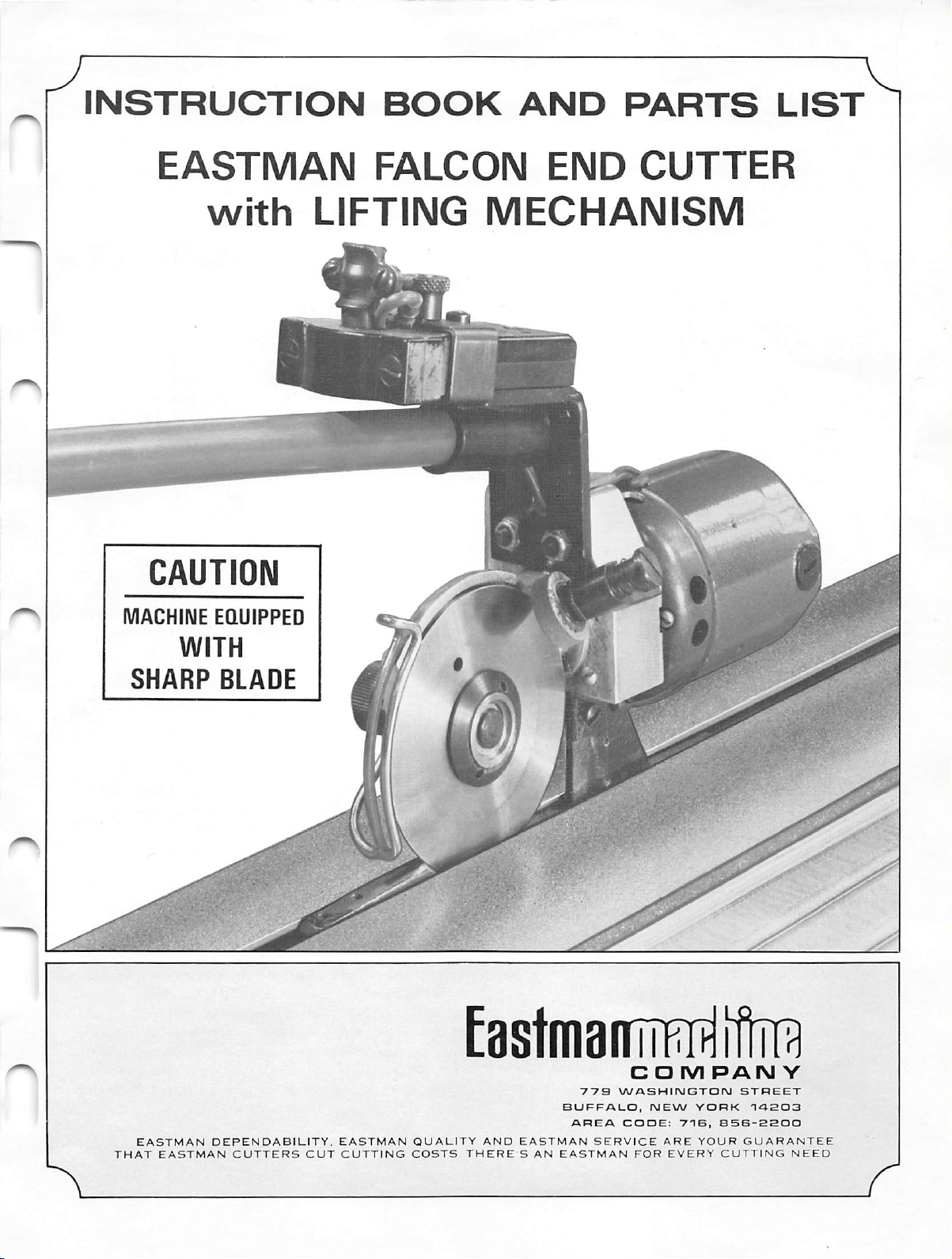
INSTRUCTION
BOOK
AND
PARTS
LIST
EASTMAN
with
CAUTION
MACHINE
EQUIPPED
FALCON
LIFTING
END
CUTTER
MECHANISM
SHARP
EASTMAN
THAT
WITH
EASTMAN
BLADE
DEPENDABILITY,
CUTTERS
CUT
EASTMAN
CUTTING
QUALITY
COSTS
Eastm8IITM^i
AND
THERE
EASTMAN
S
AN
773
BUFFALO,
AREA
SERVICE
EASTMAN
COM
WASHItNJGTON
NEW
COOE:
ARE
FOR
71B,
EVERY
YORK
YOUR
PAN
S56-SSOO
CUTTING
STREET
GUARANTEE
Y
TA203
NEED
DESCRIPTION
MOTOR
V
MAINTENANCE
The Falcon End Cutter rotary shear is
with a lifting
mechanism
for cutting across the width of
designed
for use
material whileit compensatesfor the height of a lay. The
rotary shear cutter is
matic
motor.
The
available
electric
motor
with an
is
availablein110
electric
or pneu
or
220 volts. This machine has a motor speed of 12,000
rpm. The pneumatic motor should operate at 90 psi and
has a motor speed of 20,000 rpm. A flexible handle,
attached to the cutter
assembly,
provides for
simple
and
easy execution of the cutting operation. Additionallength
handles can be made
the
track.
MAINTENANCE
available
The Falcon End Cutter is
of trouble-free
service.
The following information will aid
dependingon the length of
designedtoprovide
many years
in keeping your equipment running at its top efficiency.
CAUTION;
Before performing any of the
follow
ing procedures, make sure the attach
ment plug or air line has been disen
gagedfrom the machine.
Knife Replacement —(See page 5)
Toreplacethe knife (80C1-84HS), insert pin "A" (provided)
through hole in the knife blade below clearance portion of
standard. Insert spanner wrench
(4C1-177) and turn counter-clockwise. Once the knife lock
nut has been
removed,
slip the knife off and replace with
"B"
in the knife lock nut
new knife. Be sure, when installing the newknife, that the
name
Eastmanisshown
outward.
To
install
the
knife
lock
nut, reversethis procedure.
Microswitch(Electric Motor) —(See page 5)
Remove two screws (300C3-3) securing the microswitch
(580C1-94) to the handle adaptor and remove the two
leads.
This
microswitchiswiredinseriessothatitis
not
necessary to mark the leads that mount to this switch.
Replace with new microswitch and
CAUTION;
Excessive
switch.
soldering
reverse
heat will
the procedure.
damage
Switchin OperatingHandle—(Seepage5)
Remove two screws (300C7-2) securing the switch plate
(52C5-176) to handle and remove switch plate with switch
(580C1-48). This switch is wired in series and it is not
necessary to mark the leads that mount to this switch.
Replacewith newswitch and
reverse
the procedure.
a.
Electric
The only
is brush replacement. With a screwdriver,
slotted cap
from
b.
Pneumatic
maintenance
screws
required
for the electric motor
on rear of motor. Remove brush
slot. Install newbrush and
replace
remove
brush
cap.
For best performance, an air pressureof90 psi is
recommended. An air line oiler and filter delivering
two to three drops per minute of SAE5 spindle oil is
recommended.*
mounted
in
line
This
with
the
air
air
line
inlet
filter
hose
and
lubricator
andisnot
sold
with the EastmanEnd Cutter. Checkyour air linefor
presence of any
machine.
LUBRICATION - (See page 5)
Apply a few drops of 30 weight non-detergent
foreign
particles before installing
machine
oil daily to Point "A". Remove "Tension Nut" and apply
oil in end of shaft at Point "B". Replace "Tension Nut".
KNIFE
SHARPENING
To obtain a fine, keen edge on the blade, press lightly
against the sharpenerbutton with a constant pressure.
To
Replace
Sharpener Stone —
(See
page
5)
Remove screw (300C15-4) on sharpener bracket (35C5-58)
and
remove
screwdriver
sharpener bracket
from
handle
adaptor. Insert
in slotted button (20C12-160) and hold lock
nut on piece (21C5-5) in place. Turn counter-clockwise.
Remove and set spring (34C10-158) aside for later reassem
bly.
Remove
clockwise
sharpener bracket.
replace
bracket,
on
handle
designedtorelocateondowel
and
emery
reverse
adaptor.
screw
emery
wheel.
(301C10-9)
wheel
Remove
Toresecure
by turning
(541C1-17)
spring
washer
emery
screw
wUl
disengage
(12C15-57)
wheel
counter
to sharpener
procedure and relocate sharpener bracket
Sharpener
bracket has
been
pinsso that the
specially
sharpening
from
and
angleof the emery wheel remains the same.
is
*Not
sold
with
machine.
n
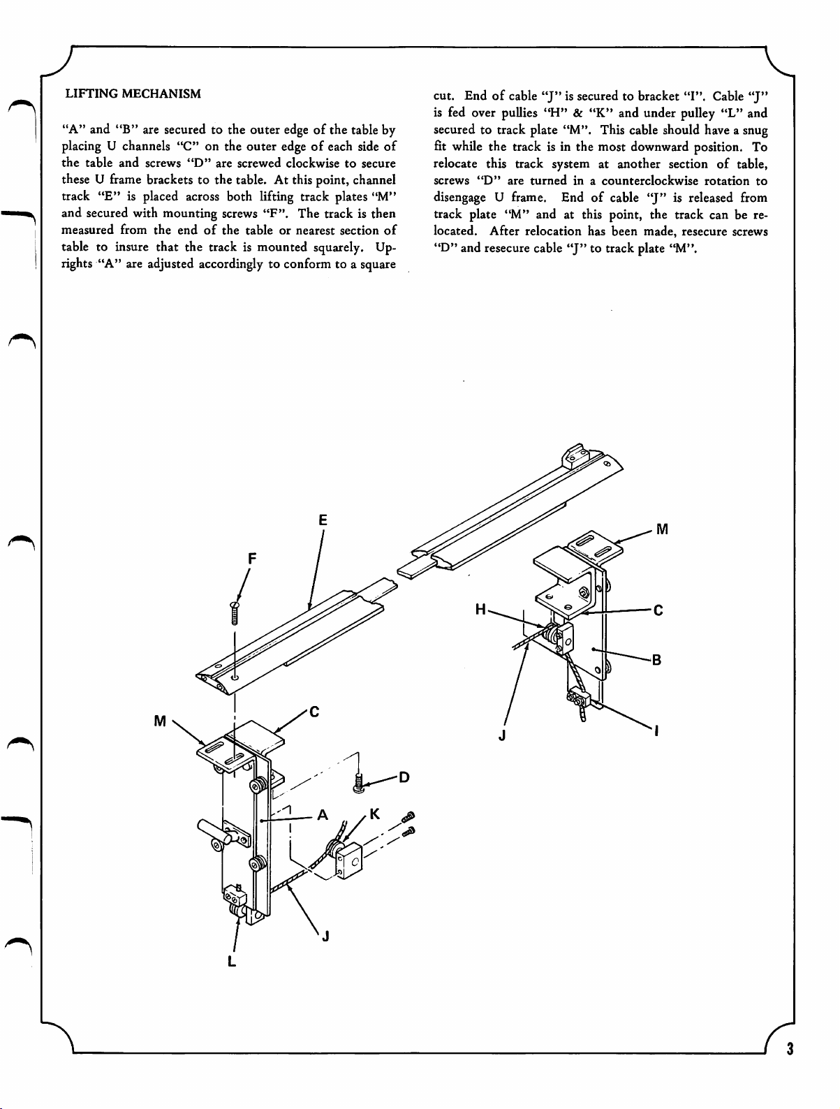
LIFTING
"A" and "B" are
placingUchannels
the
table
MECHANISM
secured
and
screws
to the outer
"C" on the outer
"D"
are
screwed
edge
of the table by
edgeofeach
clockwisetosecure
side
of
these U frame brackets to the table. At this point, channel
track "E" is
and secured with mounting
measured
from
placed
the
across
screws
endofthe
both lifting track plates "M"
"F". The track is then
tableornearest
section
of
table to insure that the track is mounted squarely. Up
rights
"A" are adjusted
accordingly
to conform to a
square
cut. Endofcable
is fed over
secured
fit
to track plate "M". This cable should
while
the track is in the most
puUies
"J"
is secured to bracket "I". Cable
"J"
"H" & "K" and under pulley "L" and
haveasnug
downward
position.
To
relocate this track system at another section of table,
screws
disengage
"D"
are
turnedina
U frame. End of cable
counterclockwise
"J"
is released from
rotation
to
track plate "M" and at this point, the track can be re
located. After relocation has been made, resecure screws
"D" and resecure cable
"J"
to track plate "M".
K ^
 Loading...