

Eastman ETS-SLS-2 Parts List


®
Table of Contents
Safety Information .................................................................................... 3
INST ALLATION.........................................................................................4
T able Preparation ..................................................................................... 4
Place Machine on T able ........................................................................... 4
Guide Wheel Installation .......................................................................... 4
Safety Cam & Home/Limit Switch Installation .......................................... 4
Encoder Track Installation ........................................................................ 5
Encoder Assembly Installation ................................................................. 5
Cable Carrier Installation .......................................................................... 5
Machine Familiarization ........................................................................... 6
SLS 2 Stack Labeling System Familiarization.......................................... 6
Control Familiarization.............................................................................. 7
User Interface T erminal Familiarization ..................................................... 8
Zero Table (Machine Home Position) ........................................................ 9
Set Origin (location of first label)............................................................... 9
Labeling ................................................................................................... 9
Loading New Files for Labeling ................................................................. 9
Raising the Labeling T ool Head ................................................................ 9
Label Threading........................................................................................ 9
Operating Adjustments.............................................................................9
Label T ension Adjustment ........................................................................ 9
Label Air Pressure Adjustment................................................................. 9
Service and Maintenance ....................................................................... 10
Recommended Spare Parts List............................................................. 10
Easicut Software Section ...................................................................... 11
Software File Relationships .................................................................... 1 1
Machine Settings ................................................................................... 14
GLOSSARY........................................................................................... 22
Service Record....................................................................................... 27
TECHNICAL DA TA ................................................................................. 28
IMPORTANT
The purchaser must instruct all operators on the proper use of the equipment.
All standard industrial safety measures and equipment should be provided to
protect the operator. Operators must be cautioned that improper or careless
use of this equipment may cause personal injury. If you do not have qualified
operators to instruct new persons, contact your Eastman sales representative
or Eastman factory direct.
Disconnect electrical power form source before proceeding with any installation, adjustment or repair of the SLS 2 Stack Labeler.
Your Eastman SLS 2 Stack Labeler is designed to travel at high speed in both
directions. Equipment should be set up with a minimum 3 foot (1 meter) clear
path at front and rear of machine. All personnel should be instructed to wear
safety glasses and stand well clear of the SLS 2 Stack Labeler when in
operation.
2
Safety Information
Throughout this manual, safety information is presented by
the use of the terms WARNING, CAUTION, and NOTE
These terms have the following meanings:
WARNING
A warning contains critical information regarding
potential safety hazards that can occur during proper
use or misuse of the machine. Failure to follow these
procedures may result in serious personal injury to
the user.
CAUTION
A caution contains instructions for the use or maintenance of the machine. Failure to follow these procedures may result in damage to the machine.
Supplementary information may be given in a Note.
ELECTRICAL HAZARD
An electrical hazard calls attention to a procedure,
practice, or the like, which, if not correctly performed
or adhered to, could result in personal injury. Do
not proceed beyond a Electrical Hazard.
Safety and Indemnification
During the life of the machine, the purchaser agrees
.
to provide to all machine users (including its own
employees and independent contractors) all relevant
safety information, including warning labels and instruction manuals. The purchaser also agrees to
maintain the safety features and working condition
of the machine, and to adequately train all users in
the safe use and maintenance of the machine. The
purchaser agrees to defend, protect, indemnify , and
hold Eastman Machine Company and its subsidiaries harmless from and against all claims, losses,
expenses, damages, and liabilities to the extent
that they have been caused by the purchaser’s failure to comply with the terms and instructions of
this manual.
General Safety Precautions
WARNING
• This machine is equipped with fast moving labeler
head. Keep hands, arms, and hair away from the
labeling area and drive system at all times. Safety
gloves, glasses, and appropriate clothing may prevent serious personal injuries.
• Disconnect the power supply to the machine and
turn off battery back-up when it is not in use or during routine maintenance, including cleaning and lubrication.
• The purchaser must instruct all operators in the
proper use of the machine according to the instructions in this manual. This training must include instruction on the potential safety hazards arising from
the use or misuse of the machine. In addition to
such training, the purchaser should provide written
work instructions as necessary to ensure correct
use of the machine for specific cutting applications.
• Do not modify this machine or disable safety features. Unauthorized modification may result in serious personal injuries to the user. Electrical connections to this machine must be made by a qualified electrician familiar with applicable codes and
regulations.
• Safety labels must be kept clean and legible at
all times. Call the Eastman Machine factory to
order replacement labels.
ELECTRICAL HAZARD
• This machine is equipped with a battery pack power
supply . Disconnect main power & turn of f (O) UIT
Power Supply (battery backup) before performing
service or maintenance to this machine.
®
3

®
The Eastman
SLS 2 Stack Labeler
is shipped partially
disassembled with all the necessary parts for proper setup
and operation. To get the best performance, familiarize
yourself with all the functions and adjustments of this
equipment. Before any operation can take place, it is
important that you carefully read and follow the instructions
in this manual in the same sequence in which they are
presented.
INSTALLATION
Table Preparation
The spreading table required to operate your SLS 2 Stack
Labeler must be smooth and level. A minimum clearance of
24 inches (61 cm) is required from the table surface to the
floor and a minimum 3 feet (1 m) around the machine. If
Magna or Z-Track is required, install track at this time.
To Level Table
Use carpenter’s level to check spreading table. Be especially careful to make sure table joints mate closely. Adjust
table feet as necessary to level table.
Tracking Installation
The SLS 2 Stack Labeler requires Magna Track, Z-Track or
Guide Wheels to guide the machine.
Magna Track or Z- Track Installation
Place track sections along table top, end to end, on the
operator’s side of the table as they will be mounted. Mount
the track as shown. Make sure the joints in track are even
and DO NOT align with seams in table. Be sure track is
mounted firmly to table.
Place the
SLS 2 Stack Labeler
on table between end
markers (marks designating left and right end of spread).
Machines equipped with grooved wheels must be placed
on the lip of Magna or Z- Track.
Locking
Screw
Guide Wheel
Assembly
Adjusting
Nut
Guide Wheel Installation
Before installation can take place the covers must be
removed for access to the mounting holes. Remove the
mounting screws on the covers. Carefully remove the covers.
Mount the guide wheel assemblies as shown. To Adjust
Guide Wheels, Loosen the locking screw and turn the
adjusting nut until guide wheel makes contact with table. Do
not over tighten. If more adjustment is required, relocate
guide wheel in next hole. Tighten locking screw when
adjustment is complete.
Limit
Switch
Actuating
Arm
Place Machine on Table
The
SLS 2 Stack Labeler
weighs approx. 400 lbs. (180 Kg.)
uncrated for a 60" machine. Wooden braces are
strapped across the underside of its cross channels and
the forklift arms should be raised to those braces when
machine is lifted.
CAUTION
When placing forklift arms under cross channels, use
care not to damage tension rods or cover.
When the
SLS 2 Stack Labeler
is shipped the Stop Wands,
Stop Cams, Cable Carrier Kit and Guide Wheel Assemblies
are removed and must be installed upon installation.
4
Safety Cam
Assembly
Safety Cam & Home/Limit Switch Installation
The Safety Cams, Limit Switch, and Home Limit Switch
Assemblies should now be installed for safety. Mount the
Safety Cams as shown at each end of the spreading area.
Loosen the limit switch actuating arm and swing into position. Secure actuating arm. Loosen the limit switch adjustment plate and lower assembly to allow the actuating arm to
make contact with safety cam. If actuating arm does not
make contact with safety cam replace arm with longer arm
provided. Replace covers and secure the flat head screws.
.94"
Spreading
Table
Non-Operator
Side
47.53"
1.50"
47.53"
48.00"
.219 (7/32) Drill
For Encoder Track
& Cable Carrier
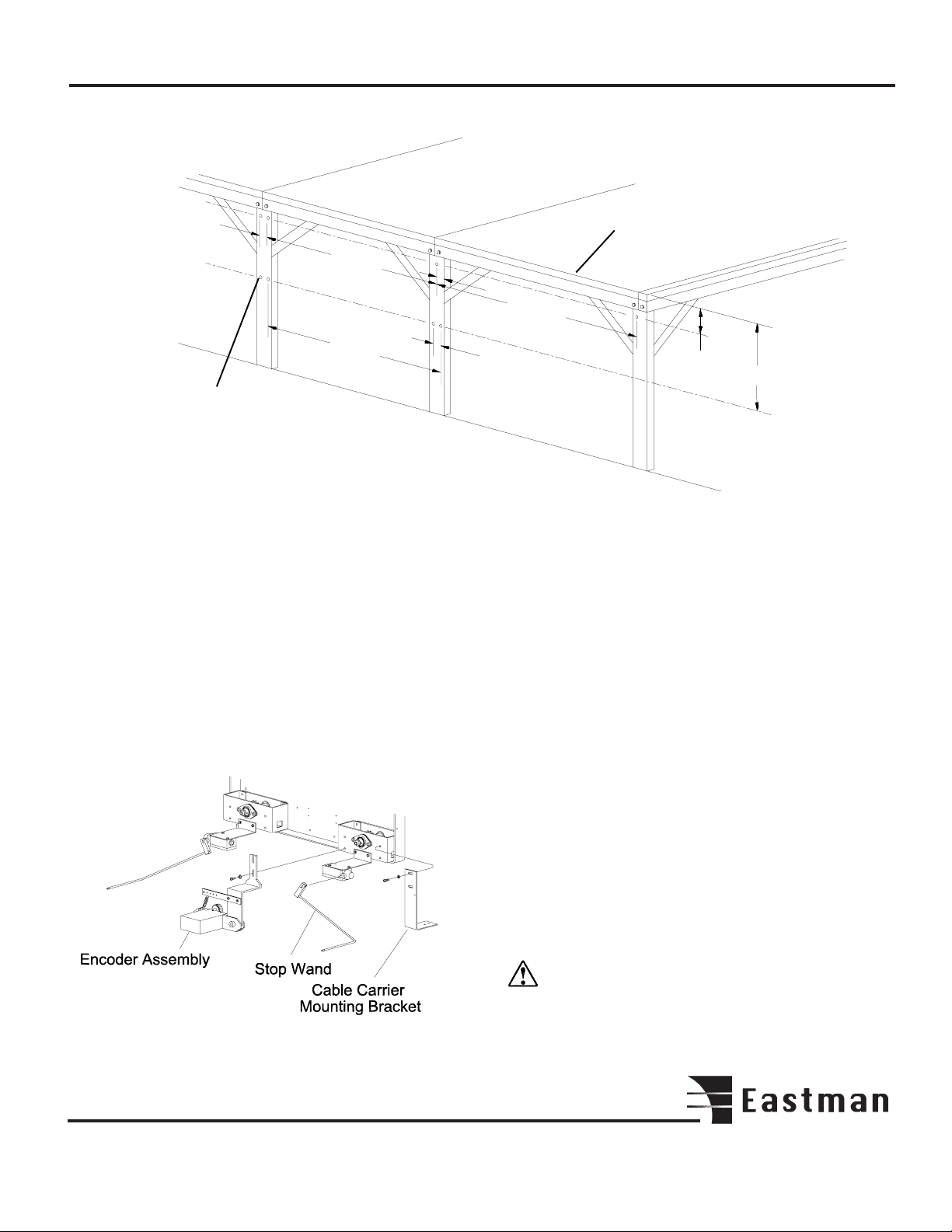
Encoder Track Installation
Proper installation of the encoder rail is very important for
accurate machine performance. The encoder track must be
level along its entire length. Drill (3) 7/32" diameter holes for
each 8' section of track, as shown. Mount encoder track to
table legs. When ALL sections of track are mounted, the
rubber encoder gear belt is then adhered IN ONE PIECE to
underside of track. Belt must be undamaged along its entire
length. If belt must be spliced, make sure that ribs of belt
remain at consistent spacing, otherwise microprocessor will
not function properly.
1.75"
5.06"
15.00"
Encoder Assembly Installation
Mount Encoder Assembly on the rear frame as shown. The
encoder gear wheel must roll smoothly along encoder gear
belt. Fasten bracket with hardware provided. Adjust tension
so gear wheel remains in continuous contact with gear belt
as the SLS 2 moves.
Cable Carrier Installation
Before the Cable Carrier Kit can be installed the table legs on
the non-operator side must be modified. Drill two (2) 7/32
diameter holes in each table leg as shown. Locate the cable
carrier, trough, mounting brackets and mounting screws.
Assemble each section and mount to the table legs.
Mount the cable carrier between the two middle trough
sections. The SLS 2 requires 25 - 30 PSI compressed air.
Locate the air line on the cable carrier. Connect air line to
pressure regulator located on the non-operator side frame
and air supply.
Once the cable carrier is secured, connect the power plug
to the socket on the back frame. Check voltage rating with
electrical rating stamped on serial number plate. If compatible, connect cable carrier cord to wall outlet.
Note: Voltage varying more than 10% (11V for 110V
machine, 22V for 220V machine) may damage your
system’s electronics.
®
5
®
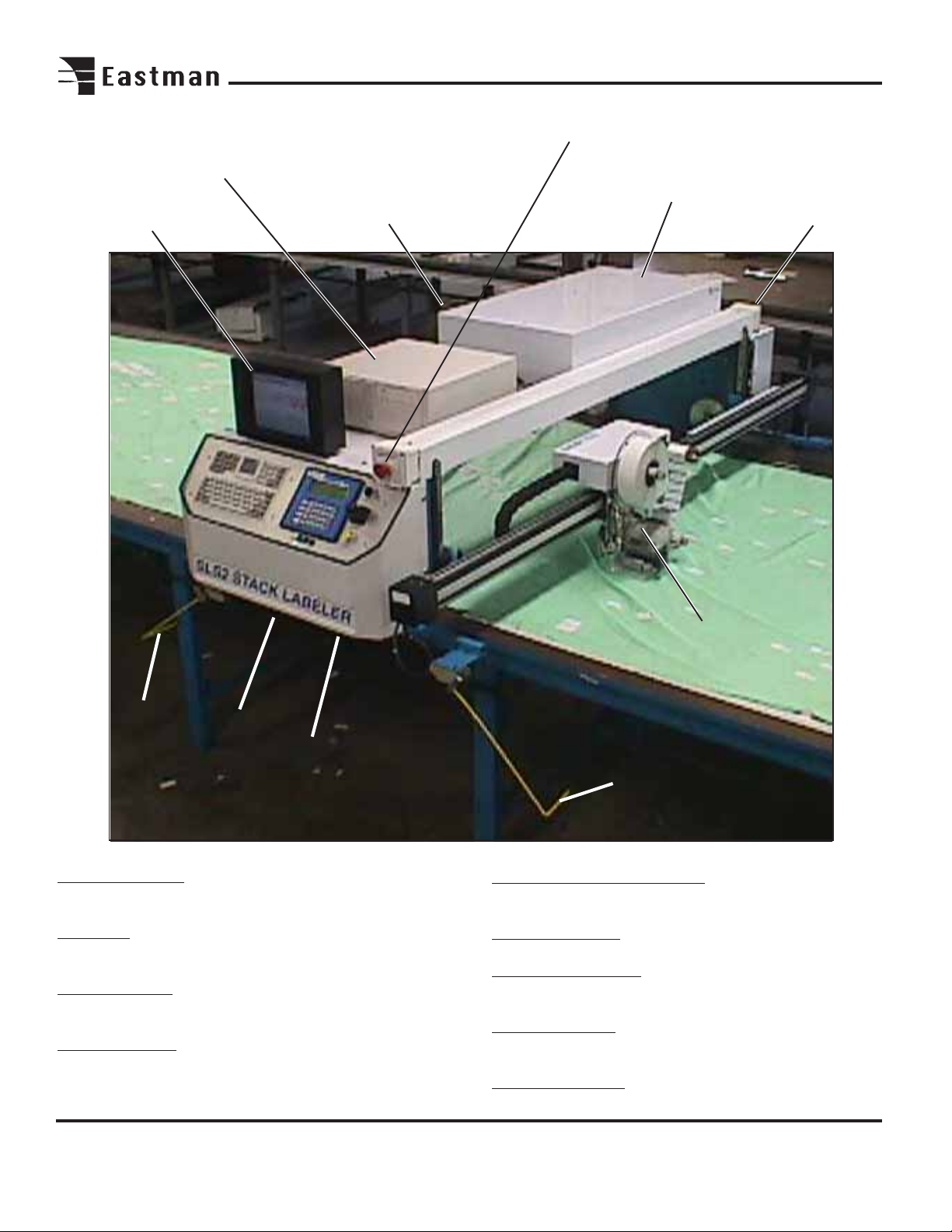
SLS 2 Stack Labeling System Familiarization
Computer
Battery
Computer Display
Back-up
Emergency Stop
On Board Control
Components
Emergency Stop
Machine
Stop
Wand
Home Limit
Switch
Stop Limit
Switch
Machine Familiarization
Computer Display: Display used for setup and run of your
SLS 2 labeling system.
Computer: Stores running programs and user labeling
files. Disk drive available for loading labeling files.
Battery Back-Up: Reserve power in the event main power
is interrupted (10 minute minimum supply).
Emergency Stop: Activates power to all drive circuits. Pull
on, push off.
Labeler T ool Head
Machine
Stop
Wand
On Board Control Components: Electrical components
used to control the SLS 2 labeling system.
Labeler T ool Head: Tool used to apply labels to material.
Machine Stop Wands: Deactivates power to all drive
circuits when wand strikes object in its path.
Stop Limit Switch: Switch is activated by cams located
near each end of labeling area.
Home Limit Switch: Switch is activated by cam to set
zero location on table.
6
T ouch
Mouse Pad
Computer
Display
Computer
Disk Drive
Emergency
Stop
Auxiliary
Switch
(future use)
Keyboard
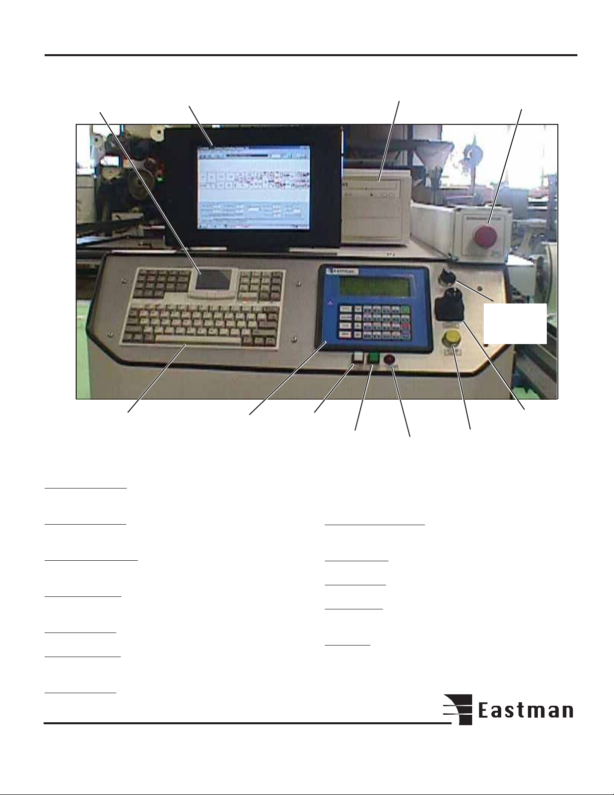
UIT T erminal
Control Familiarization
Touch Mouse Pad: Used to control the cursor on the
computer display .
Computer Display: Display used for setup and run of your
SLS 2 labeling system.
Computer Disk Drive: Disk drive used to down load
labeling files.
Emergency Stop: Activates power to all circuits. Pull on,
Push off.
Auxiliary Switch: Available for future use.
Joy Stick Control: For manual movement of machine and
labeling head.
Machine Pause: Push to stop machine when in automatic
labeling mode. Press NEXT on UIT to resume.
Label Feed
Labeler Error Indicator: Indicates error in label position.
Press label feed to reset.
Printer On/Off: Press to activate labeler tool head.
Labeler Feed: Press to manually feed label.
UIT T erminal: Used for operator interface of machine. See
operating instructions for more details.
Keyboard: Used to enter labeling data on the computer
display .
Printer
On/Off
Labeler
Error
Indicator
Machine
Pause
Joystick
Control
®
7

®
MOVE: Press to access menu.
Press 1 to send SLS 2 to home position.
Press 2 to send SLS 2 to label origin position.
UP: Pressing UP causes the elevator to move up.
DOWN: Pressing DOWN causes the elevator to move down.
LEFT : Pressing LEFT causes the SLS 2 Labeler to move to
the left.
Right:: Pressing RIGHT causes the SLS 2 Labeler to move
to the right.
ST ART : Press ST ART to begin automatic labeling mode.
UIT T erminal
User Interface Terminal Familiarization
The UIT (User Interface T erminal) features a 33 key membrane keypad and a four line display . Commands are issued
via the keypad and information is communicated back to
the user through the display . Through the UIT the operator
may position the plotter carriage, enable automated movement, and manually cut and mark.
Commands are sent to the computer by pressing specific
keys or key sequences on the UIT . Each key on the UIT can
have a function and characters related to that key (note that
not all keys have both a function and characters). Commands that require data entry following the pressing of a
FUNCTION key the UIT will automatically set itself in anticipation of the expected type of input.
Some commands require only one key to be pressed while
other commands require multiple keystrokes and may sometimes prompt the operator for input.
A description of commands follows:
SET ORIGIN: Press to set the first label position on the
table. The laser pointer marks the origin position. T o
adjust offset, see software section.
ZERO T ABLE: Press to activate the zeroing function on
the carriage. The carriage will move to the home limit
switch cam. This point is set as home position.
SPEED: Press to set fast/slow machine movement.
/6: Press to move labeler head away from operator.
/9: Press to move Labeler head toward the operator.
NEXT: Press to resume automatic labeling when machine
pause is pressed.
ABORT: Press to abort command.
ENTER: Press ENTER to accept command.
Operation
After setup is complete and the power and airline is connected, the SLS 2 is now ready for Initialization.
Important
To stop the SLS 2 at any point during
operation, either:
-Press the Emergency Stop button (Red).
-Hit Machine Sop Wands.
-Press Machine Pause button (yellow) on main control
panel.
WARNING: Safety cams should always be checked
for proper operation with the SLS 2 before any automatic
labeling takes place.
Activate battery back-up to ON (I) position. Activate the
computer by pressing the ON (I) button. The computer
display will run through the computer start-up program.
Pull the Emergency Stop button to activate power to the
drive circuit. Start the EASICUT software by double clicking
the EASICUT software icon on the computer display. This
will load the default test.cmd file. Enter label text for the
required fields using the keyboard. Select OK.
The log in screen will appear. Enter the user name and password. Select OK when complete. The UIT Display will show
DESIGN LOADED. Press ENTER on UIT T erminal to continue.
8
Zero Table (Machine Home Position)
Press ZERO T ABLE on UIT T erminal to locate the “machine
home position” of the table. This will raise the elevator to the
top position and accelerate machine to the “machine home
position”.
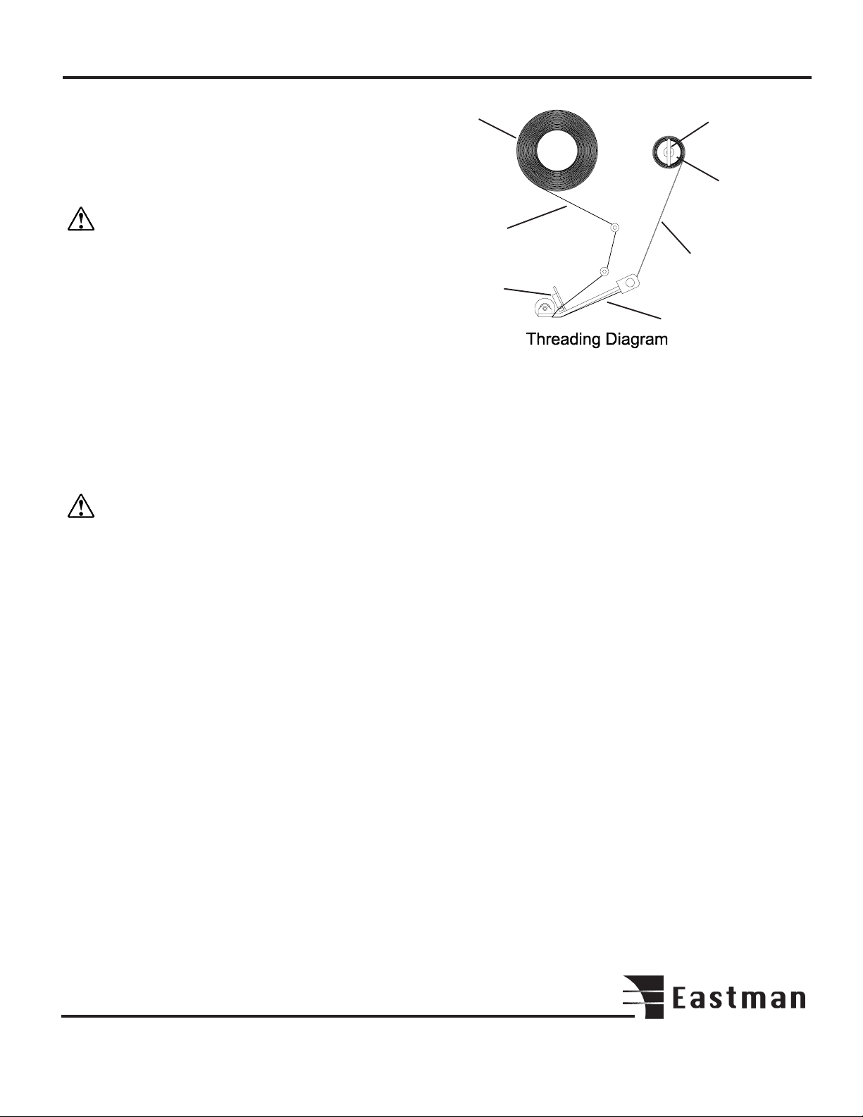
Label roll
T ake-up
spool clip
T ake-up
spool
Note: The “Machine Home Position” is created when
the Home Limit switch strikes the Stop Cam mounted
on the table.
The UIT display will show TABLE ZERO OK when task is
complete. Press enter on UIT terminal to except. The UIT
display will show ready .
Set Origin (location of first label)
Press the Printer ON/OFF (Green) button to activate labeler
tool head. Using the joystick, move the SLS 2 to the first
label position. The red laser should be in the center of the
first label. Press Set Origin to except. The elevator will lower
to locate the table surface. The SLS 2 Labeler is now ready
to begin labeling.
Note: Labeling area must be clear of all personnel and
objects before starting the labeling process.
Labeling
T o begin labeling press Start on the UIT T erminal. The SLS
2 will begin labelling. After the final label is applied the machine will return to the original label origin position.
Loading New Files for Labeling
Load a file by opening the file menu and clicking on the
desired file. Enter label text and press enter on the keyboard to accept. Select the "PLOT" icon on the computer
display to load design. Press ENTER on the UIT Terminal
to accept new design.
Note: Files are organized by type and are displayed on the
menu according to which type is selected. For example,
if you wish to use a file generated in CMD format, open
the list files of type menu and select CMD. The file
menu will then display all files with a CMD extension.
Raising the Labeling Tool Head
Press the UP or DOWN on the UIT terminal to raise or lower
the labeling tool head.
Labels
on this
side
Label Web
Roller
Lever
Skid Plate
Label Threading
Press Printer ON/OFF (green) button to turn off printer.
Remove take-up spool clip. Lift the roller lever to separate the
printer rollers. Discard used label web material and label roll
core. Load new label roll as shown. Release roller lever.
Press Printer ON/OFF button to continue.
Optional: Label web material may be threaded above the skid
plate as required to prevent pushing material or
interfering with take-up spool performance while
labeling.
Operating Adjustments
This machine is adjusted and tuned at the factory for optimal
performance. No Adjustments other than normal setup are
necessary. However, if after continued use the performance
level becomes unacceptable, the following procedures
should be carried out before repairs are considered.
Label T ension Adjustment
The label tension adjustment is located under the labeler tool
head cover. Remove the cover to access the take-up clutch.
Rotate the knurled adjusting knob clockwise to increase and
counterclockwise to decrease tension.
Label Air Pressure Adjustment
The labeler pressure regulator is located on the back side
frame. To adjust, remove back cover. Locate the regulator
valve. Pull the "Adjust" knob up and turn clockwise to
increase pressure and counter clockwise to decrease pressure. After adjustment is made, push knob down to lock in
place.
®
9
 Loading...