


Congratulations
Congratulations in selecting an Eastman EC3 Conveyor. With over 100 years of experience in the cutting
room, Eastman is a world leader in cutting equipment. Every Eastman employees takes pride in each machine we build and back it with unprecedented support. Our Technical Service department is made up of a
dedicated staff of professionals with years of experience installing, troubleshooting and servicing the EC3
Conveyor Each technician is familiar with all aspects of the machine including mechanical, electrical and
software.
Eastman Machine Company provides technical phone support and on-site service as required. We offer
several affordable Extended Warranty plans that allows you to continue the superior technical support well
after the machine is past standard warranty. If you require on-site technical support or would like to schedule
additional training, please call our headquarters in Buffalo NY to arrange for a technician.
Technical Support:
Eastman Machine Company
779 Washington Street
Buffalo, NY 14203
United State of America
Phone: 716-856-2200
Fax: 716-856-2068
Limited Warranty. Eastman warrants to the buyer that the equipment shall be free from defects in materials or workmanship for
a period of 180 days commencing on the date of invoice. Any goods or parts claimed by the buyer to be defective must be returned
to Eastman, freight charges prepaid, within the 180 day warranty period. If Eastman determines that the goods or parts are defective
in materials or workmanship, Eastman’s sole obligation under this warranty shall be, at Eastman’s sole option, to repair or replace
the defective goods or parts or to provide the buyer a credit equal to the portion of the purchase price allocable to the defective goods
or parts. This warranty shall not apply if defects are caused by product misuse or neglect, if the machine has been altered or modified
by the buyer, or if other than genuine Eastman belts, emery wheels, knives or parts are used in the machine. THIS WARRANTY
IS THE ONLY WARRANTY APPLICABLE TO THIS PURCHASE. SELLER DISCLAIMS ALL OTHER WARRANTIES, EXPRESS
OR IMPLIED, INCLUDING, BUT NOT LIMITED TO, THE IMPLIED WARRANTIES OF MERCHANTABILITY AND FITNESS FOR
A PARTICULAR PURPOSE.
Limitation of Liability. Eastman’s liability to the buyer, and the buyer’s remedies from Eastman, whether in contract, negligence,
tort, under any warranty or otherwise, shall be limited to the remedies provided in the foregoing Limited Warranty. In no event shall
Eastman have any responsibility or liability to the buyer for (a) any special, indirect, incidental, or consequential damages, including,
but not limited to, loss of use, revenue, or profit, even if Eastman has been advised of the possibility of such damages, or (b) any
claim against the buyer by any third party. The price stated for the product sold is a consideration for limiting Eastman’s liability.
IMPORTANT
The purchaser must instruct all operators on the proper use of the equipment. All standard industrial safety
measures and equipment should be provided to protect the operator. Operators must be cautioned that
improper or careless use of this equipment may cause personal injury. If you do not have qualified operators
to instruct new persons, contact your Eastman sales representative or Eastman factory direct.
Disconnect electrical power source from before proceeding with any installation, adjustment or repair of the
EC3 Automated Cutting System.
2
Form E-526

Table of Contents
REVISION PAGE ............................................................................................................................................... 4
OVERVIEW ....................................................................................................................................................... 5
Safety Information ............................................................................................................................................. 5
Safety Zone and Stop Devices........................................................................................................................... 7
FAMILIARIZATION............................................................................................................................................7
User Interface Terminal ................................................................................................................................... 9
UIT Controls: ................................................................................................................................................... 10
OPTIONS Mode .............................................................................................................................................. 13
Software File Relationships ............................................................................................................................. 15
OPERATION AND SETUP .............................................................................................................................. 17
EC3 Power Up Procedure ............................................................................................................................... 17
Running A JOB ................................................................................................................................................ 17
Setting up for a Different Materials .................................................................................................................. 17
Changing tools in tool head ............................................................................................................................. 18
EC3 Conveyor Pressure Calibration ................................................................................................................ 19
CALIBRATION PROCEDURE ........................................................................................................................ 21
Pen X-Y offset-Pen mark (dot) .......................................................................................................21
Calibrate Gantry in X-Axis ..............................................................................................................22
Calibrate Gantry to Belt ..................................................................................................................22
Calibrate Secondary Conveyor Encoder ......................................................................................23
Fine Tuning Secondary Conveyor Encoder for Long Length Pieces .........................................26
Size Calibration ...............................................................................................................................28
Square Calibration ..........................................................................................................................29
Mount Theta Calibration .................................................................................................................30
Mount XY Calibration ......................................................................................................................31
Cut Normal Calibration ...................................................................................................................32
Cut Tool Calibration ........................................................................................................................33
Punch Calibration ...........................................................................................................................34
Cut Tool Calibration ........................................................................................................................35
Maintenance Schedule ....................................................................................................................................37
MAINTENANCE .............................................................................................................................................. 37
Maintenance Check List for EC3 Conveyor ..................................................................................................... 40
Replacing Linear Bearings ............................................................................................................................... 46
Changing Conveyor Belt .................................................................................................................................. 47
Loading ABS File to the MEI Board.................................................................................................................. 52
TROUBLESHOOTING .................................................................................................................................... 54
User Interface Terminal Error Messages .........................................................................................................54
ELECTRICAL SCHEMATICS & PNUEMATIC DIAGRAM..............................................................................64
Form E-526
3

12/30/2003 - Initial Release of the EC3 manual
1/31/2004 - Revision of the EC3 manual
9/28/04 - Added Pnuematic Diagram 31-9000-19
REVISION PAGE
4
Form E-526

Safety Information
WARNING
A warning contains critical information regarding potential safety hazards that can occur during proper
use or misuse of the machine. Failure to follow these procedures may result in serious personal injury
to the user.
CAUTION
A caution contains instructions for the use or maintenance of the machine. Failure to follow these
procedures may result in damage to the machine. Supplementary information may be given in a Note.
Safety And Identification
During the life of the machine, the purchaser agrees to provide to all machine users (including its own
employees and independent contractors) all relevant safety information, including warning labels and
instruction manuals. The purchaser also agrees to maintain the safety features and working condition
of the machine, and to adequately train all users in the safe use and maintenance of the machine. The
purchaser agrees to defend, protect, indemnify, and hold Eastman Machine Company and its subsidiaries harmless from and against all claims, losses, expenses, damages, and liabilities to the extent
that they have been caused by the purchaser’s failure to comply with the terms and instructions of this
manual.
OVERVIEW
General Safety Precautions
WARNING
This machine is equipped with very sharp and dangerous tools. Keep hands, arms, and hair away
from the cutting area and drive system at all times. Safety gloves, glasses, and appropriate clothing
may prevent serious personal injuries. Disconnect all power sources to the machine when it is not in
use or during routine maintenance, including cleaning and lubrication. The purchaser must instruct all
operators in the proper use of the machine according to the instructions in this manual. This training
must include instruction on the potential safety hazards arising from the use or misuse of the machine.
In addition to such training, the purchaser should provide written work instructions as necessary to
ensure correct use of the machine for specific cutting applications.
WARNING
The purchaser must provide appropriate safety measures and equipment as recommended in this
manual. Observe all statutory requirements concerning the use of hazardous machinery that apply to
your location.
Do not modify this machine or disable safety features. Unauthorized modification may result in serious
personal injuries to the user. A qualified electrician, familiar with applicable codes and regulations,
must make electrical connections to this machine.
Misuse of this machine or use of this machine as part of another machine may result in serious
personal injuries to the user.
Safety labels must be kept clean and legible at all times. Call the Eastman Machine factory to order
replacement labels.
Form E-526
5

CAUTION
Eastman Technology Systems equipment is not designed for use in conditions of extreme temperature
or humidity. Operating this equipment in an environment outside the specified ranges may result in
damage and will void the warranty.
Acceptable operating temperature range: 10ºC to 35ºC (50º to 95ºF).
Acceptable operating humidity range: 20% to 80% (non-condensing).
Altitude: We anticipate that the system will operate within all specifications at an altitude up to 1000 m
above mean sea level.
Transportation: During transportation and storage, the system is capable of withstanding ranges from
-25oC to 55oC and for periods not exceeding 24 hrs. at up to +60oC.
Lifting/Moving: The lifting or moving of this system must be in accordance with the installation requirements. Failure to adhere to these installation requirements may cause injury to persons or
hinderance or the machine performance.
Hearing protection devices are recommended for prolonged exposure to the noise.
Electrical Component Specifications
Specifications
Voltage Current Frequency # of phases
Computer 120 VAC 6 Amp 50/60 Hz Single
Gantry E-box 120 VAC 10 Amp 50/60 Hz Single
25 HP Blower 230 VAC 60 Amp 50/60 Hz Three
440 VAC 30 Amp 50/60 Hz Three
Gantry 120 VAC 1.2 Amp 50/60 Hz Single
Low Voltage 5/12 VDC 2/3 Amp 50/60 Hz Single
Power Supply
6
Form E-526
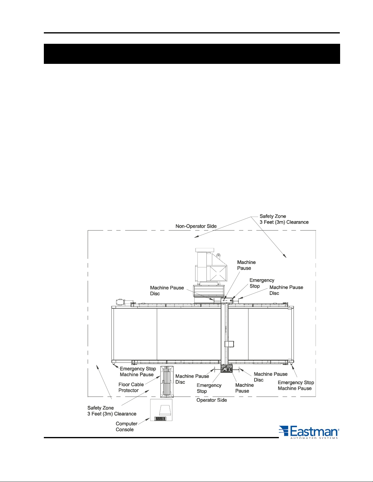
Safety Zone and Stop Devices
PAUSE Buttons/Disc
The yellow buttons above the control panel and on the nonoperator side of the gantry as well as the
pause discs on each side of the gantry will pause the machine. Activating either the button or the
pause disc will execute a controlled stop of the plotter, with the machine remaining fully powered.
After releasing the pause button or resetting the pause discs and pressing NEXT on the UIT keypad,
the cutter will resume cutting the work in progress. Pressing ABORT will cancel the job.
EMERGENCY STOP buttons
There are red Emergency Stop buttons located on each side of the gantry as well as on the operator
side right and left ends of the conveyor. Pressing any of the Emergency Stop buttons will execute a
controlled stop of the gantry before cutting all power to the motors and e-box. To release an Emergency Stop condition, pull out the Stop button hit the ABORT key on the UIT keypad. The table must
be re-homed by pressing the ZERO TABLE button before restarting the cutter. Emergency stop mats
are also available as an option.
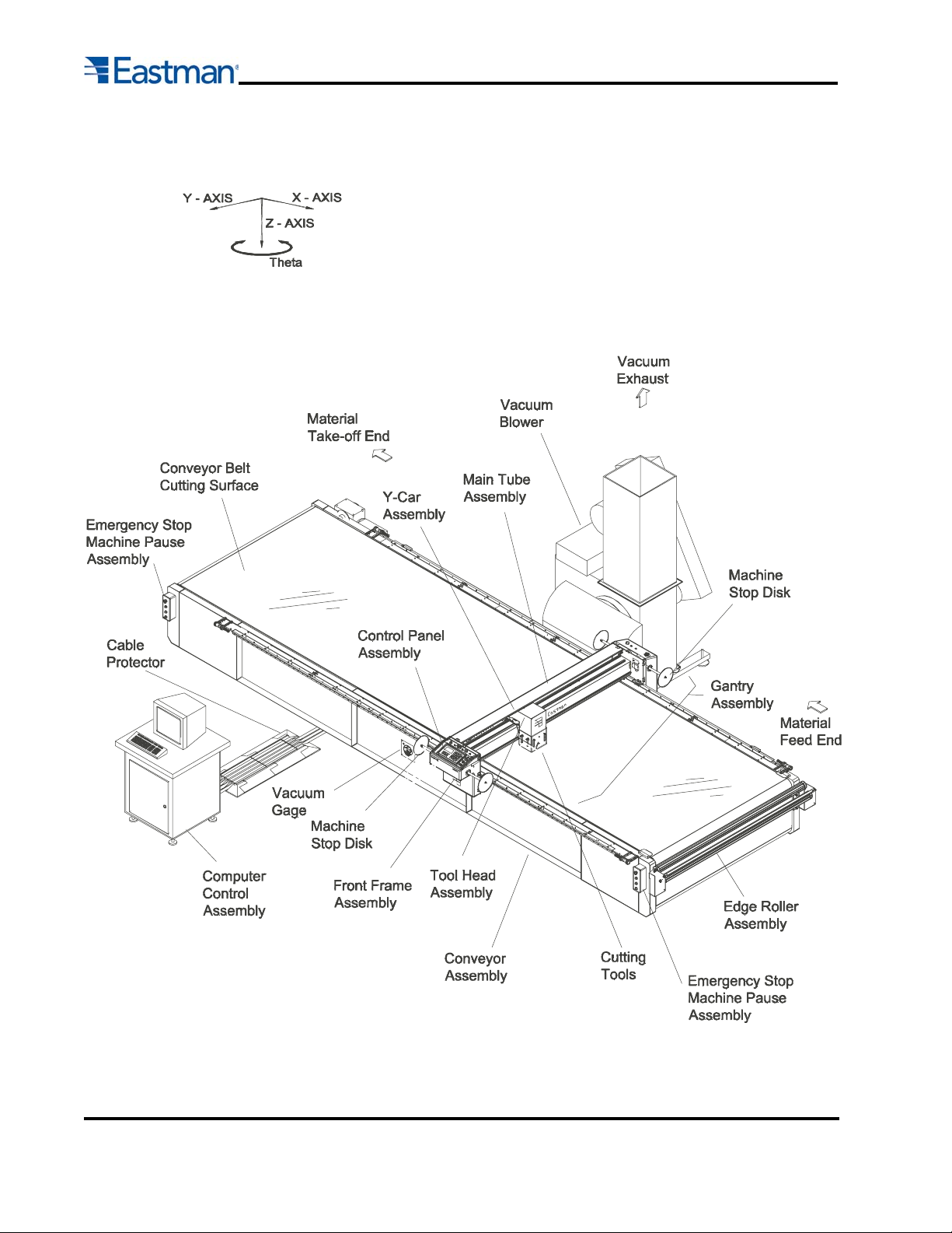
FAMILIARIZATION
Form E-526
7
8
Form E-526
User Interface Terminal
The EC3 Gantry is controlled by the UIT (User Interface Terminal) located on the operator side of the
gantry. After plotting a marker file from the computer the UIT allows the user to operate the machine from
the gantry. With it's push button keypad and four line LED display the operator can easily home the table,
zero a panel or begin cutting a file. The LED display shows the current status of the cutter as well as any
error messages.
Commands are sent to the plotter by pressing specific keys or key sequences on the UIT. Each key on
the UIT has a function and up to two characters. (Note that not all keys have both a function and characters). The UIT can be set in one of three modes: Function, Alt Left, and Alt Right. On commands that
require data entry following the pressing of a FUNCTION key the UIT will automatically set itself in either
Alt Left or Alt Right in anticipation of the expected type of input. Alt modes can only be accessed during
data entry.
The commands are grouped as follows:
Functions: This is the default setting for the keypad. Pressing a key in this mode initiates the com-
mands in bold face type at the top of a key. (e.g. <ZERO TABLE>)
Alt Left: Enables characters shown on the lower left side of a key during data entry.
Alt Right: Enables characters shown on the lower right side of a key during data entry.
Some commands require only one key to be pressed while other commands require multiple keystrokes
and may sometimes prompt the operator for input.
Form E-526
9

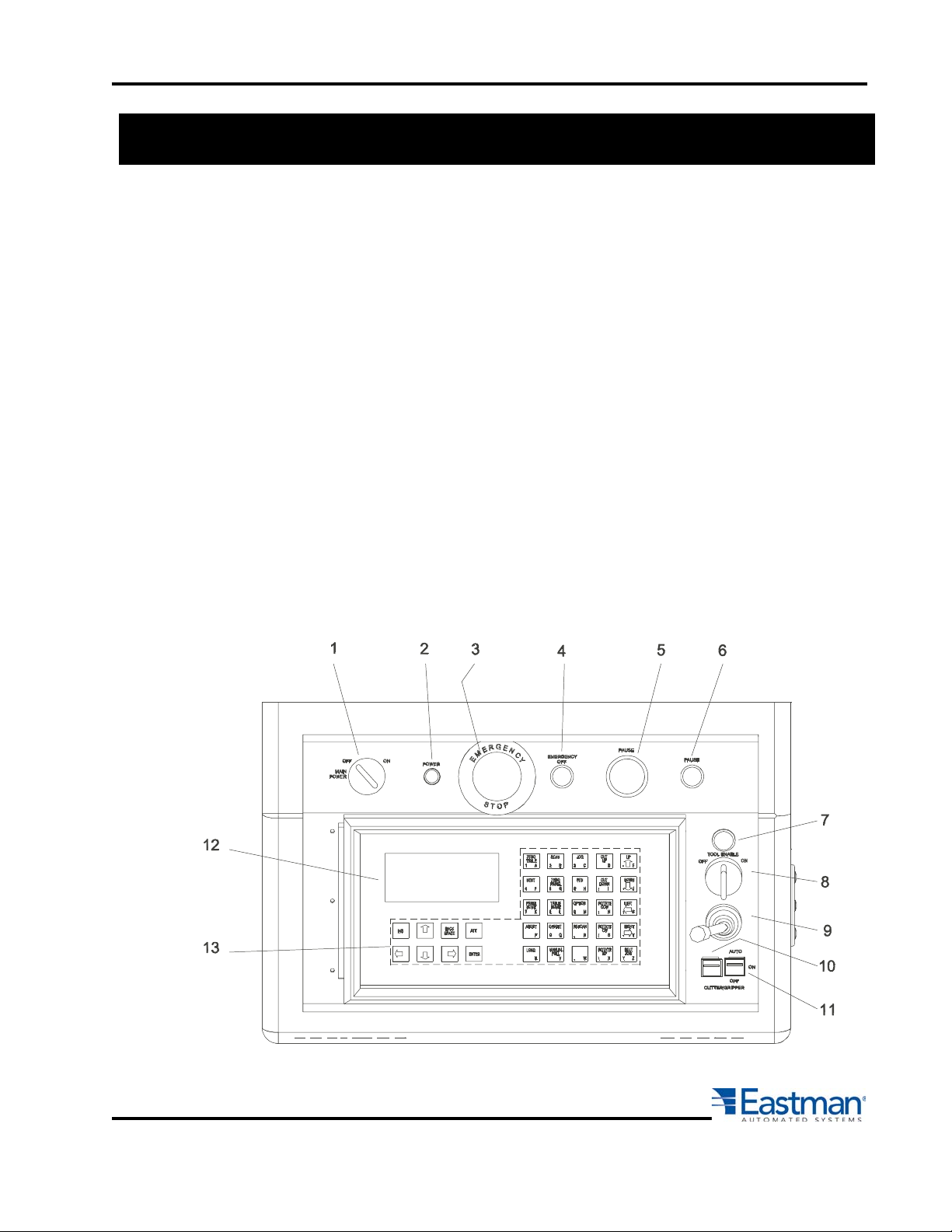
UIT Controls:
1. Gantry Main Power Switch: Turns the power to the gantry on or off.
2. Power Lamp: Indicates if the gantry is on or off.
3. Emergency Stop Button: When the Emergency Stop button is pressed the Gantry will decelerate to a
stop and power will be cut to all axes of motion. The Stop Buttons are 12 VDC
normally closed switches and are located on both the operator and non operator sides of the gantry as well as at each end of the machine. After releasing
the emergency stop the gantry should be "Homed" before proceeding.
4. Emergency Stop Lamp: Indicates if the Emergency Stop circuit is active. If the LED is lit, check each
emergency stop button to make sure they are pulled out.
5. Pause Button: The "Pause Buttons" are generally used to pause a cutting operation to clear material,
make adjustments, inspect work, etc. Pausing the machine stops all axes of motion but
does not cut power to the amplifiers. The servo motors are powered and maintain position.
Yellow pause paddles are located on each side of the Gantry as well as pause buttons on
the gantry and at each end of the machine. To resume cutting simply press the NEXT key
on the gantry keypad and the program will resume where it left off.
6. Pause Lamp: Indicates if the Pause circuit is active. If the LED is lit, check each of the pause buttons and
paddles to make sure they are not active.
7. Tool Enable Lamp: Shows if tool devices are enabled.
8. Tool Enable Switch: Turns the tool head on and off and can be toggled at any time during machine
operation. The tool head can be turned off to prevent the tools from coming down
during test runs of a file.
9. Joystick: The Joystick is used to jog the Gantry in the X or Y direction. A fast or slow jog speed can be
selected using the jog button on the keypad. The gantry can only be jogged in either the X or Y
direction at one time and is used to position the Gantry before zeroing the table.
10. EZ Pull Knife Switch: The EZ Pull switch is used in conjunction with the EZ-Pull option for the M9000
table. (Reference the EZ-Pull manual if you have this option.)
11. EC3 Conveyor Switch: The EC3 conveyor switch is used to lock the gantry to the cutting belt when
jogging. This is used during calibration to insure the belt and gantry speeds are
identical.
12. Display: Is a four line 20 Character display used to communicate information between the machine and
the operator. The display may request information from the operator as well as indicating current
status and/or error codes.
13. Command Buttons:
Commands are sent to the plotter by pressing specific keys or key sequences on the UIT. Each key on the UIT
has a function and can have up to two other characters related to that key (Note: not all keys have both a
function and characters). The UIT can be set in one of three modes: Function, Alt Left, and Alt Right. On
commands that require data entry following the pressing of a FUNCTION key the UIT will automatically set
itself in either Alt Left or Alt Right in anticipation of the expected type of input. Alt modes can only be accessed
during data entry.
10
Form E-526

The commands are grouped as follows:
Functions: Default setting for UIT. Accesses the commands in bold face type at the top of a key.
Alt Left: Enables characters shown on the lower left side of a key during data entry.
Alt Right: Enables characters shown on the lower right side of a key during data entry.
Some commands require only one key to be pressed while other commands require multiple keystrokes and
may prompt the operator for additional input.
ABORT: If running a cut file pressing the "ABORT" key causes the carriage to come to an immediate and
controlled stop. Once stopped the UIT will prompt the operator to either press ABORT or NEXT.
Pressing ABORT will exit from the current panel or motion. Pressing NEXT will continue the current
panel or motion.
ALT: Toggles the current mode of the UIT. The ALT key is only active during data entry. Pressing the ALT key
will toggle the UIT between ALT RIGHT and ALT LEFT to allow the user to access all alphanumeric
characters on each of the keys. A left or right arrow in the upper right of the display shows the current
mode.
ALPHA-NUMERIC: A thru Z. Active during data entry. Accessed by pressing ALT, LEFT or RIGHT.
BACKSPACE: Moves the cursor one position to the left when in data entry mode.
CURSOR LEFT: Moves the cursor one space to left and will erase the current character during data entry.
CURSOR DOWN: Not active.
CURSOR RIGHT: Not active.
CURSOR UP: Not active.
CUT DOWN: Drops the primary cutting tool to the cutting surface. This allows the operator to manual cut
straight across the table using the "CUT DOWN" key and the joystick. If the cut direction is
changed the tool will lift rotate and plunge to align the blade with the cut direction.
CUT UP: Lifts the primary cutter from the cutting surface. This key is used in conjunction with the "CUT
DOWN" key when cutting manually.
DOWN: Jogs the gantry carriage in the negative Y-axis direction. (Towards the operator) The gantry carriage
will move as long as the key is pressed or until the carriage encounters a limit switch. See "JOG" for
speed change.
ENTER: Sends information from the UIT to the computer. It is only active during data entry mode.
INS: Not active
JOG: Toggles the carriage jog speed from fast to slow when using the joystick or jog keys. The high speed is
the manual MOVE VELOCITY while the slow speed is the SLOW VELOCITY value in MACHINE.INI
setting. When the program is first enabled the default slow manual move speed is set to MOVE
VELOCITY from the MACHINE.INI file
LEFT: Jogs gantry to the negative X-axis direction. (To the operators left side) The gantry will move as long
as the key is pressed or until the carriage encounters a soft limit. See "JOG" for speed change.
LOAD: Allows user to load a new CMD file from the UIT panel. After pressing LOAD the UIT will display the
current file and prompt user for a new file name. Using the ALT mode the operator may then enter the
new file name (.CMD extension need not be included) using a valid file in the current directory. When
done typing the file name the user must press ENTER to accept the new file.
Form E-526
11

NEXT: After zeroing the table the "NEXT" button is pressed to begin cutting, draw and or marking the current
file plotted to the cutter. The first time "NEXT" is pressed the UIT displays the marker length while the
second time the "NEXT" key is pressed the gantry begins cutting.
OFFSET: Moves the gantry carriage from it's current position to the offset position of the primary cutter. This
effectively moves the primary cutter into position over the reference point (usually the pen device or
laser pointer).
OPTION: Allows option mode commands to be entered in the UIT. Values are set by pressing a two letter key
and then inputting a new value for a specific setting. The available commands are listed in the
OPTIONS section in this manual.
PANEL HOME: Moves the gantry carriage to the current PANEL HOME position set either by the most recent
PANEL ZERO or in the current cut file.
PEN: Toggles the pen tool up or down. The default is pen up.
RESCAN: Causes the cut file program to reset to the top of the current panel.
RIGHT: Jogs the gantry in the positive X-axis direction. (To the operators right side). The gantry will move as
long as the key is pressed or until the carriage encounters a soft limit. See "JOG" for speed change.
ROTATE 90: Rotates the Z-axis Tool Spindle 90 degrees counter clockwise from it's current position.
ROTATE CCW: Rotates the Z-axis tool spindles counter clockwise. The tools will rotate as long as the key is
held down. The rotation speed can be changed between fast and slow by toggling the "JOG"
button.
ROTATE CW: Rotates the Z-axis tool spindles clockwise. The tools will rotate as long as the key is held
down. The rotation speed can be changed between fast and slow by toggling the "JOG"
button.
SCAN: Allows user to scan to a specific panel within the current cut file. Press scan and the UIT will prompt
for a panel number. The UIT automatically go into ALT LEFT mode and allow user to select a panel
number. Press ENTER to accept the panel number.
TABLE HOME: Moves the gantry carriage to the TABLE HOME position. The table home position is defined
by the location the gantry, Y-car and tool spindles stop when using the "ZERO TABLE" function. The "TABLE HOME" key allows the operator to return to the zero position without the
time required to zero the table.
UP: Jogs the gantry carriage in the positive Y-axis direction. (Away from the operator) The gantry carriage
will move as long as the key is pressed or until the carriage encounters a limit switch. See "JOG" for
speed change.
ZERO PANEL: Sets the current gantry and Y-car position as the home position. The cutter will use this
position as it's zero reference point when cutting a file. The "ZERO PANEL" key should be
used to position the cutting or marking tools on the material before pressing "NEXT" to begin
cutting. The laser pointer is used to position the tool head on the material. The selected tool
will begin cutting/marking at the referenced laser position.
ZERO TABLE: This function homes the gantry by moving each axis one at a time until they hit their respective
home switches. This will square the Gantry as well as return each axes to it's known starting
point. The Home Position can be offset from the home switches as determined in the Easicut
software.
12
WARNING The "ZERO TABLE" key must be pressed each time the system is Powered
Up, Easicut is started or an E-STOP is activated. Failure to Zero Table can
result in the Gantry and/or Y-car traveling past table limits and crashing into
end stops.
Form E-526

OPTIONS Mode
Options mode is used to change plotter operation variables through the user interface terminal. Changes
made using the options commands are not saved and are lost as the plotter program is exited. Should you
wish to make a permanent change, (for example, offset calibrations) you must write them down and then
enter them into the "Machine Setting" in Easicut.
To enter the options mode press the OPTION key on the UIT. The display will then prompt for a two-letter
option. After typing the two letter command press the ENTER key and you will be prompted for a value or
the action will take place immediately. If prompted, input the new value and press the ENTER key again.
Note that if you do not enter a new value and press the ENTER key, the current value is maintained.
Option codes values can also be entered on the computer keyboard in the plotter status window. The two
letter option codes are not case sensitive.
(AA) Change Acceleration: Sets the acceleration rate of the carriage.
(AB) Airbrush On/Off: Activate and deactivates airbrush option. (If available.)
(BB) Layer Names On/Off: Toggles the layers names command on or off. With layer names turned off this
allows CMD file formats that reference CUTN and CUTF commands to be
compatible with the new motion control software.
(CC) Change Laser Max Power: For laser plotters only, it sets the maximum power for the laser. Ex-
pressed as a number between 0.0 and 1.0. This will adjust the cutting
kerf for specific cut speeds. It should never be set above 0.95. This
command is only available on machines that have a laser cutting tool.
(Not Pointer)
(DD) Digitizing Mode On/Off: Enters or exits the pattern digitizing mode. (See the section on Digitizing in
the EasiCut manual.)
(EE) Change Overall Rate:
(FF) Laser Service Modes On/Off: For laser cutting machines only. Sets the software mode to enable sev-
eral power and alignment tests. (Not for laser pointers)
(GG) Load Cut File: This command loads the current CMD file active in the Easicut window to the plotter file
for cutting. This is the same as plotting the file through the Easicut software from the
computer terminal.
(HH) Change Slow Speed: Sets the slow JOG speed of the gantry, Y-car and Z-axis. This command can
be used to slow down the gantry when trying to jog the laser pointer to a fixed
point on the table.
(HOME) Panel Home: This does the same function as the ZERO TABLE key on the UIT. By typing this
command into the Plotter Status window on the computer, you can zero the table
without walking over to the gantry.
(II) Change Time Interval: Sets the update interval for the motion control card. There is no reason ever to
adjust this value except during calibration of the M9000 system at the factory.
Changing this variable will result in inaccuracies in cutting.
(KK) Key Dump On/Off: Enables or disables the key dump feature. Key dump is normally off. With it
turned on the signature of the key pressed is displayed on the computer's screen.
This is a valuable diagnostic tool that helps troubleshoot UIT keypad problems.
(LL) Change Cut Speed: Sets the top speed during manual use of the primary tool. Changing this variable
does not effect the cutting speed when cutting in automatic mode.
(NN) Next: After plotting a file, this command starts the machine cutting or penning the active panel. Like
Form E-526
13

pressing NEXT on the UIT this can be typed into the Plotter Status window at the computer.
(OO) Options: Allows the operator to enter the "Options Mode" of the UIT from the computer terminal. This
command is only available from the computer keyboard and duplicates the OPTIONS key on
the UIT.
(PP) Pause On/Off: Toggles on or off any <PAUSE> command within the current CMD file. With pauses
turned off the plotter will move from panel to panel without prompting for the NEXT
command. This feature works in conjunction with CMD files that have pre-designated
pauses in the file for product inspection. (This is not related to the pause buttons on
the gantry.)
(QQ) Exit Plotter W: Exits the Easicut program. When reopening Easicut the table must be homed by
pressing the ZERO TABLE button on the UIT keypad. Failure to home the system will
result in the gantry running into the end stops and/or causing damage to the system.
(RR) Set CMD repetitions: Sets the number of times to repeat the current CMD file. Note that the next
repetition of the CMD file will start from the plotter position at the end of the last
repetitions of the CMD file. When repetitions are used zero marks are disabled.
(SS) Change Scale Factor: Sets the scale factor of the current CMD file. This allows user to expand or
contract the size of the entities within a CMD file by an input coefficient. For
example entering a value of 0.5 will yield parts 50% of normal, therefore
entering a 2.0 will yield parts twice the normal size.
(TT) Change Laser Minimum Speed: Available on M90 Laser cutting machines only. Sets the minimum
speed at which the laser tube will fire. This is useful for reducing
cutting kerf as the gantry decelerates to a stop. If set to high, parts
may not be cut all the way to side intersections.
(UU) Tools On/Off: Toggles the primary tool on or off. Works like Tool On/Off switch.
(VV) Speed Change: Sets the top speed during dry haul when the machine is neither marking nor cutting.
It is the speed that the machine moves between cuts.)
(WW) Pen Speed Change: Sets the top speed during manual use of the pen device. Pressing the Option
button followed by WW will change the speed that the pen will mark in manual
mode. The pen must be down and the gantry jogged before it takes effect.
(YY) Reference Mark On/Off: Toggles all zero marks in a CMD file either on or off. Note that it affects both
the <MARK> command and <VMARK> command present in many CMD
files.
(ZP) Zero panel: Sets the current gantry and Y-car position as the home position. The cutter will use this
position as it's zero reference point when cutting a file. (See ZERO PANEL button.)
(ZZ) Set Display Units: Toggles the UIT and computer display between different units of measurements like
inches (IN), feet (FT), centimeters (CM). The current units setting is indicated in the
upper right corner of the display.
(11) X Offset Change: Sets the X offset of the primary tool from the reference laser pointer. Setting the
Offset from the UIT or Plotter Status screen is only temporary while the system is
powered. The cutter will default to the original settings after software is exited or
system is powered down. All offset setting need to be made on the calibration screen
or in the Option/Machine menu to be permanently saved.
(22) Y Offset Change: Sets the Y offset of the primary tool from the reference laser pointer. Setting the
Offset from the UIT or Plotter Status screen is only temporary while the system is
14
Form E-526

powered. The cutter will default to the original settings after software is exited or
system is powered down. All offset setting need to be made on the calibration screen
or in the Option/Machine menu to be permanently saved.
(33) Z Offset Change: Sets the rotational offset of the primary tool from the sensing point. Setting the Offset
from the UIT or Plotter Status screen is only temporary while the system is powered.
The cutter will default to the original settings after software is exited or system is
powered down. All offset setting need to be made on the calibration screen or in the
Option/Machine menu to be permanently saved.
(44) Cut Up Time Change: Set the time delay from when the tool up command is set and the gantry begins to
move. This prevents the gantry from moving and catching material while the tool is
going up.
(55) Cut Down Time Change: Set the time delay from when the tool up command is set and the gantry
Software File Relationships
Easicut is Eastman Technology’s Windows XP based plotter software (Other versions of Windows available).
When opened, Easicut can read in several data file types to initialize the plotter’s settings. These data files
are ASCII text files with specific formats, which must be correct to be read. Some files can be edited through
the Easicut software, while others may be accessed using Microsoft Notepad. All are located in the Eastman
directory in the Easicut or Plotter folders. The following is a short description and a chart of the various files:
PLOTTER.KEY: Required on all machines using a UIT and on some older M90 models. This file
maps the keypad data coming from the UIT to the plotter program.
DESIGN.CMD: The file containing a pattern’s coordinates and commands read by PLOTTERW. The CMD
file uses Eastman’s proprietary file format. Easicut automatically converts several file formats
to CMD files when operator selects and opens them in the software.
MACHINE.INI: Contains values pertaining to calibration, velocity profiling, table dimensions, and layer to tool
mapping. Easicut writes to this file as changes are made in the Machine Setting window.
MACHINE.INI is read by Easicut, modified as necessary (for example, to accommodate a
change in tool offsets) and sent to PLOTTERW. It is important to always keep a copy of your
latest MACHINE.INI so that you can always reload your machine setting if something becomes corrupt.
PLOTTER.SRV: Optional. Used only on plotters with laser cutting device. Contains default values for
laser test firing and troubleshooting.
PLOTTER.DRL: Required only when <DRILL> function is called by CMD file. Contains default values
used by <DRILL> function when specified in CMD file.
MATERIAL.INI: Contains tool control information relating to different material types. The JOB file temporarily
overwrites the machine settings set in the MACHINE.INI file and takes precedence over the
JOB.INI file.
JOB.INI: Contains tool control information relating to different material types and or cut files. The JOB
file temporarily overwrites the machine settings set in the MACHINE.INI but does not take
precedence over the MATERIAL.INI files.
Form E-526
15
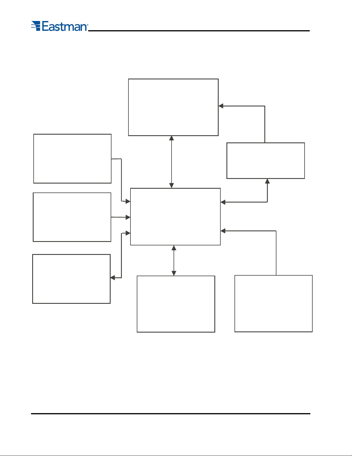
MATERIAL.INI File
These files contain the tool
settings for various materials.
The settings over ride the
MACHINE.INI and the
EASICUT.JOB files
Motion Control Software Functions
PLOTTERW
Motion Control Software called by
Easicut and runs the machine. This
program takes the DESIGN.CMD file
and creates the motion profile based
on the JOB, MATERIAL and
MACHINE.ini file parameters
DESIGN.CMD File
This is the cut file or marker file
that is opened in Easicut and
sent to PLOTTERW to be cut.
EASICUT.JOB
These files contain the tool
settings for various jobs. The
settings over ride the
MACHINE.INI file but are
superseded by a
MATERIAL.INI file.
MACHINE.INI File
This file contains the machine
settings, calibrations, table
parameters, etc. and is written
to by the EASICUT software
Easicut 2000
This is a Windows based interface
software used to enter parameters
and load files. The information from
the UIT, MACHINE.INI, MATERIAL
and/or JOB files are combined and
loaded into the PLOTTERW
UIT
User Interface Panel is located
on the gantry and is used to
enter information into
EASICUT and run simple
command sets.
Easicut Dash Board
User Interface in the Easicut
software that allows you to
map tools, change cut speeds
and pressures on the fly.
These changes are only
temporary and are not saved to
the Machine.ini
16
Form E-526

OPERATION AND SETUP
9. To run same pattern, repeat steps 7 & 8.
EC3 Power Up Procedure
1. Turn on the Computer CPU and wait until computer is fully booted.
2. Turn on the Gantry using the gantry On/Off switch above the UIT panel.
3. Power the Gantry and Conveyor E-Boxes.
4. Start the EasiCut software by double-clicking on the Windows Desktop.
**To power down the system, reverse the power up sequence starting with closing EasiCut
Running A JOB
1. Spread material on the feed end of conveyor, making sure it is straight and parallel with X-axis.
2. Press the TABLE ZERO button on UIT. This will bring the gantry to it's calibrated home position. (Only
required when first powering up the machine or after hitting an E-Stop)
3. Turn on the convey vacuum to hold material down.
4. Jog belt 12-24 inches to remove slack in the gray link belt. If the belt is not jogged after starting the blower
and before cutting, it can result in patterns overlapping after he first conveyor pull.
5. Position laser pointer to the edge of the material where you want to begin cutting.
6. Send the cut file to the gantry by pressing the "Cut" icon in Easicut.
7. Press the ZERO PANEL button on UIT.
8. Press "NEXT" on UIT. This will calculate the pattern length and width compared to the table length and
width. If the pattern is larger than the cutting surface an error message will appear on the UIT. Pressing
NEXT a second time will start job cutting.
Setting up for a Different Materials
1. Remove all material from previous job.
2. Open cut file for new job
3. Change tools according to job requirements.
4. Adjust over cut setting in Easicut according to material thickness. *
a) Go to | Options | Job | Layers |
b) Select tool from pull down menu
c) Change Overcut value in the Overcut window.
* NOTE: The tool settings and cut pressures can be saved in a job file and loaded into the cutter for each
material being cut. (See Easicut Manual or Help Screen for JOB files)
Form E-526
17

Changing tools in tool head
1. Turn the power off to the gantry making sure it is unable to move.
2. Remove desired tools from tool mounts by:
a) Loosening the (2) allen head screws on the tool holder.
b) Carefully slide tool holder off tool mount.
3. Attach desired tools to empty tool mounts. If a different tool type is installed, re-map the new tool type to
the tool holder. Reverse tool removal process.
CAUTION Failing to re-map a tool after changing tool types can result in damage to
the belt, tool and/or tool spindle.
Example: Changing a Punch to a Drag Knife ill cause punch to drag across
the belt.
4. Open the job file in Easicut that corresponds to the current job and material.
5. Tools DO NOT need to be recalibrated unless cut accuracy is critical to .010 or less. If calibration is
needed go to Tool Calibration section of this manual.
18
Form E-526
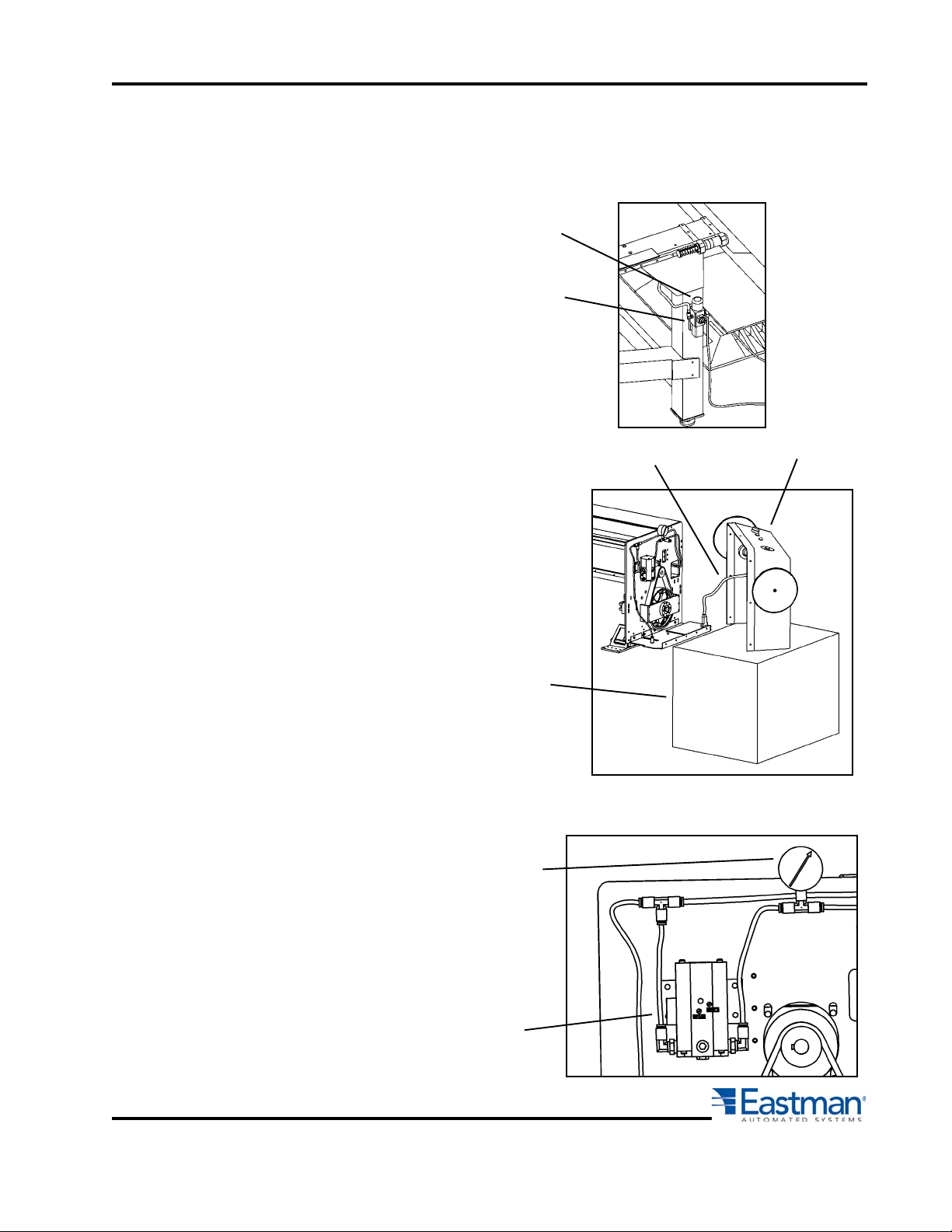
EC3 Conveyor Pressure Calibration
Note: Pressure calibration is set by an Eastman Service Technician at machine installation.
Calibration settings should be changed by the customer ONLY if prior settings are found to
be inaccurate.
Knob
Main Pressure
1. Set main pressure regulator to
125 psi by turning regulator
knob.
Regulator
2. Remove back cover and leave cable
connected to PC board. Place on a
support that will lift back cover to
relieve strain on cable.
3. Remove toolhead air tube
from pneumatic transducer
output port. Install calibration
gauge at transducer output.
Cable
Back Cover
Support
Calibration
Gauge
#27-26024
Form E-526
Pneumatic
Transducer
19
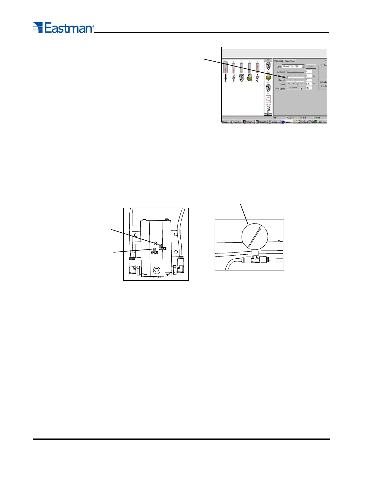
Pressure Slide
Switch
4. Set Easicut cut pressure at 10 psi
and adjust at regulator using zero
screw adjustment.
Pressure meter should read 10 psi
at gauge.
5. Set Easicut cut at 100 psi..
6. Push "cut up" and "cut down"
on control panel UIT.
7. Adjust "span" screw until calibration gauge reads 100 psi..
Zero Screw
Calibration Gauge
#26024
Span Screw
Repeat steps 5 through 10 at least 3 times. Be sure to push tool up/down on
control panel between each test calibration.
8. Compare Easicut cut pressures to calibration gauge pressures at 10, 20,
40, 60, and 100 psi..
9. Remove calibration gauge, attach tool head air tube to pneumatic transducer
output port. Remove shunt wire connector and replace with rear cover
connector. Attach back cover assembly.
20
Form E-526

CALIBRATION PROCEDURE
The following calibration procedures are used to calibrate each machine tool to one another to insure accurate
cuts between tools. The calibration are initially done at machine installation and should not need to be done
unless a tool mount is changed. The calibration numbers are stored in the machine.ini file in the Easicut 2000
directory. A backup copy should be stored in that directory as well on a disk.
The EC3 tool calibration should be performed in the following order:
1. Pen X-Y offset.
2. Calibrate Gantry in X-axis.
3. Calibrate Gantry to Belt.
4. Calibrate Secondary Encoder to Belt (If Applicable).
5. Fine Tune Secondary Encoder for Long Lengths (If Applicable).
6. Table sizing.
7. Automatic gantry squaring.
8. Tool mount X-Y for all tools.
9. Theta axis offset.
10. Tool Calibration (circles and squares).
11. Test Cut Using Design.cmd.
12. Test Cut Using Design.cmd and production material.
Before beginning the calibration procedure:
- Remove all cutting and punch tools from all tool mounts.
- Check that the pen tool is rigidly attached to the pen mount
- Open the Easicut 2000 software and "zero" the table by
depressing the TABLE ZERO button on the operator UIT.
Tools required :
- 2.5" to 3.5" wide masking tape.
- High quality tape measure that has inches and cm.'s.
- 60" to 72" Roll of paper for test cutting.
- Sample production material for test cutting.
- Tools that will be used in production cutting.
- #2 Pencil.
Pen X-Y offset-Pen mark (dot)
This calibration procedure establishes the offset between the pen and the laser pointer. The laser pointer
is considered the zero point for the machine.
a) Put a small length of masking tape under the pen mount.
b) Press "PEN" several times on the UIT to make a mark on the masking tape.
c) Press "ZERO PANEL" on the UIT.
d) Using the UIT joystick, move the gantry and tool head to position the laser pointer over the pen mark
on the masking tape. For precise positioning of the gantry movement use “Option” HH on the UIT to
set a very slow jog speed of about 0.1 cm/sec. (0.04 in/sec)
e) Read the "X" and "Y" values on the UIT display and write them down.
Form E-526
21

f) Click on Options/Calibration/Mount X-Y/Pen 1 in the Easicut 2 menu and enter the negative of the
values for X-Y in their respective Offset windows.
Example: (If X=+0.27 on UIT then enter -0.27).
g) Verify the Pen Mount X-Y offset by pressing "PANEL HOME" on the UIT. Press "PEN" and the
mark should be exactly over the previous pen mark. If not repeat steps (a) through (e) again until
you have calibrated the pen offsets correctly.
h) Click “APPLY” then “OK” to save the changes. Press “CANCEL” to keep original settings.
Calibrate Gantry in X-Axis
This calibration procedure establishes the proper calibration for the movement of the Gantry in the X-Axis.
This will insure that the cut piece are cut accurately in the X direction. If this calibration is off the cut piece
can become longer or shorter. (Calibration of the Y-axis will be done later in the calibration procedure.)
a) Press the "ZERO TABLE" button on UIT to Home the conveyor.
b) Move the Gantry to far right of conveyor.
c) Place a piece of brown masking tape under the pen.
d) Press the "PEN DOWN" button on the UIT.
e) Using the Joystick or "JOG" button, mark the piece of tape in the "Y" direction only
f) Using the Joystick or "JOG" button, Jog the Gantry to the far left about 3 meters.
g) Press the Slow Jog key on the UIT and jog the gantry until the UIT reads an exact multiple of 1 cm.
h) Make a mark on a second piece of tape by repeating steps c, d and e.
i) Measure the length between the two marks.
j) If the measurement is not exactly equal to the measurement on the UIT then:
• On the menu bar click on OPTION/MACHINE then on the "SIZE" tab
• Increase the "X Calibration" number to increase the length between lines. Decrease the number to
decrease the distance between lines. (Note: Use very small increments for fine tuning)
• Open a file and click on the "CUT" icon for new data to take effect.
• Repeat procedure until measurement is within 0.01 cm
Calibrate Gantry to Belt
This calibration calibrates the movement of the Gantry with the movement of the cutting belt. If this
calibration is off, every time the conveyor pulls more material on to the cutting belt piece size and cuts will
be off in the X-direction. It can cause pieces to overlap.
a) Move the Gantry to far right of conveyor and turn on the vacuum.
b) Jog the belt approximately 5-6 feet to remove any slack in the system.
b) Place a piece of masking tape below the laser pointer. Using a pen or pencil mark the laser on the
piece of tape.
c) Push the "EC3 Conveyor Switch", located on the bottom right hand side of the gantry panel to the
down position. This will lock the gantry to the cutting belt when jogging the belt.
d) Press the "BELT JOG" button on the UIT. Both the gantry and belt will jog down the table together.
22
Form E-526
e) Watch the laser with respect to the mark on the masking tape. The laser pointer may initially jump
ahead of the mark by as much as an 1/8" but should remain constant throughout the length of the
table. When the "JOG BELT" button is released the laser should line back up with the mark.
f) If the laser drifts down the table or the mark does not line up when the "BELT JOG" button is
released then:
• On the menu bar click on OPTION/MACHINE then on the "SIZE" tab.
• Increase the "Conveyor Calibration" number if the pointer drifted ahead. Decrease the number to
if the laser pointer drifted behind the mark.
Note: Use very small increments for fine tuning (+/-1 count).
• Open a file and click on the "CUT" icon for new data to take effect.
• Repeat procedure until laser pointer no longer drifts.
Calibrate Secondary Conveyor Encoder
The secondary conveyor encoder is an option which increases the cutting accuracy in the X direction of the
conveyor. The encoder tracks actual cutting belt movement in order to compensate for initial slack in the
link belt or slip in the cutting belt. This calibration procedure calculates the counts/cm movement of the
cutting surface. Not all machines are equipped with these feature. If your machine does not have a
secondary encoder function you can skip this step.
Caution The Secondary encoder calibration should be performed when the belt or
any rollers are replaced. Periodically checking the encoder calibration will
insure the cutting accuracy.
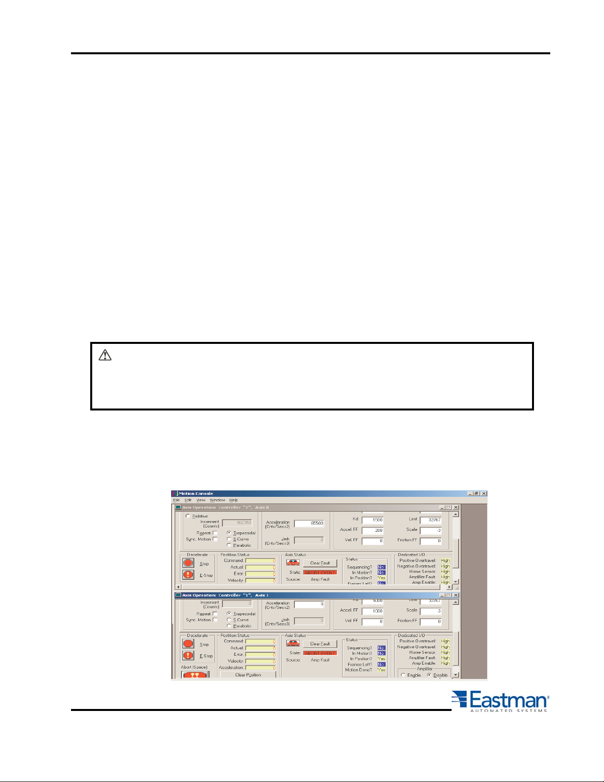
a) Minimize Easicut 2 and open the MEI setup program. (Located in c:/Program Files/Eastman/Options/
setup.exe).
b) Click on address 0x320 so that it is highlighted.
c) Double click on Axis 0 and Axis 1 to open up both axis windows. If you do not see an Axis 1 then you
may not have a secondary encoder and you can move on to step 6..
Form E-526
23
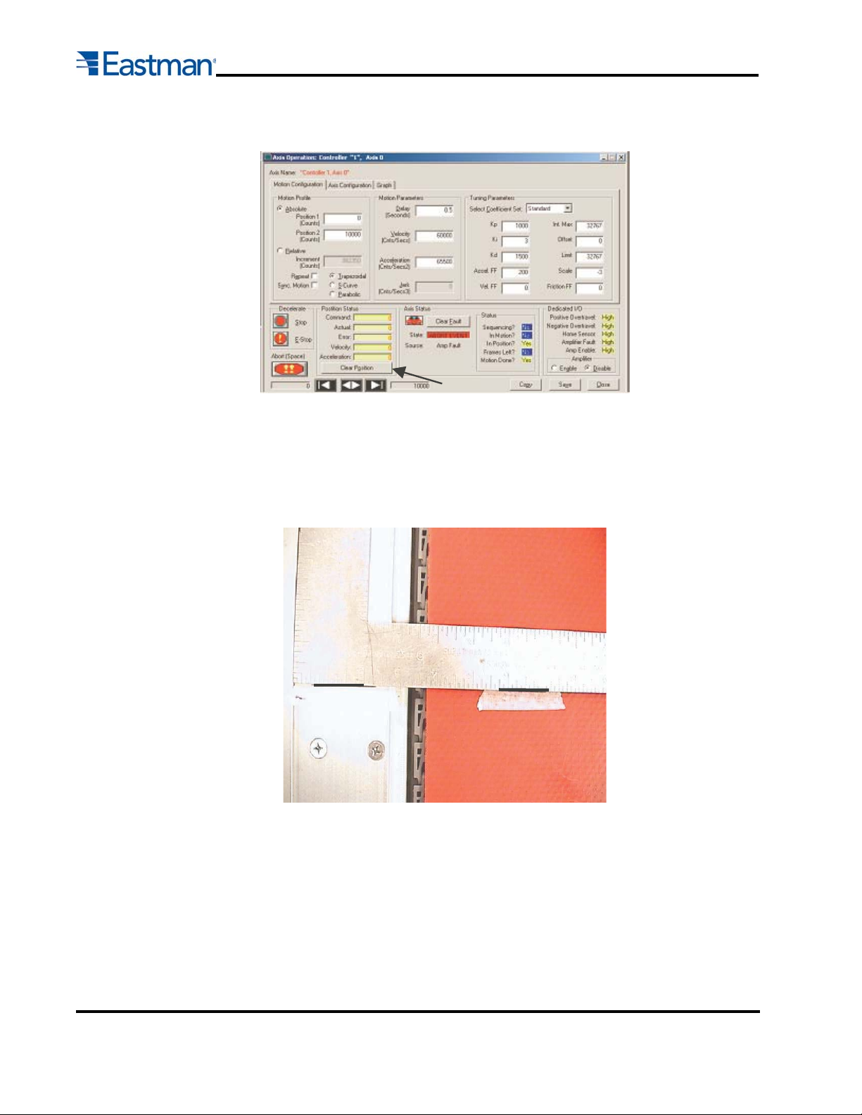
d) On Axis 1 click the "Clear Position" button to reset the axis.
e) Turn the conveyor vacuum on, open Easicut and go to the operator side of gantry to do a manual pull.
Press the MANUAL PULL button, then press 3-0-0 and the ENTER key. The belt will begin to move
300cm, taking out any slack in the link and cutting belts.
f) Using a right angle rule, mark the rack plate and the belt (or a piece of tape) with a fine pen to indicate
the belt starting position. Mark the belt and rack plate approximately 100 cm (3 ft.) from the right hand
side of machine.
24
g) Go back to MEI program and clear Axis 1.
h) Click on Easicut 2 and do a manual pull of 160 cm by going to the UIT and pressing the MANUAL
PULL button. Press 1-6-0 then the ENTER key to begin the manual pull.
i) Using the right angle square, put another piece of tape on the belt in line with the initial start position
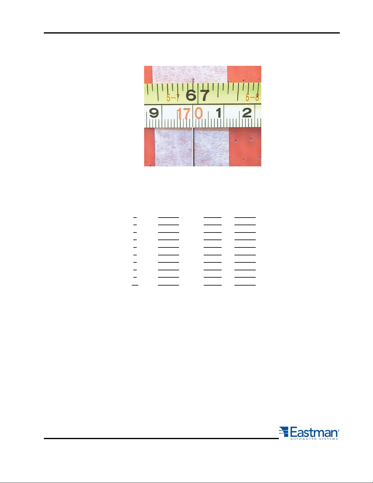
on the rack plate. Mark the new position of the belt on the tape using the pen. Measure the distance
the belt moved between the initial mark and the new mark. Measure in centimeters starting at the 10
cm mark to eliminate variations in the tape measure. Remember to subtract the 10 cm from your final
measurement. (Example: 170.07 cm -10cm = 160.07)
Form E-526
j) Record the number of encoder counts from MEI axis 1 and the measured belt distance in cm. (Mea-
sure to the nearest 0.01 cm)
k) Repeat steps (g) through (j) 10 times recording each measured move distance and encoder count.
Test Encodr Counts Measured Encoder
Number From MEI Distance Counts/cm
1 524,441 160.05 3276.73
2 524,402 160.02 3277.10
3 524,672 160.12 3276.74
4 524,721 160.15 3276.43
5 523,754 159.85 3276.53
6 524,362 160.02 3276.85
7 525,064 160.23 3276.94
8 524,784 160.14 3277.03
9 524,458 160.05 3276.84
10 524,492 160.07 3276.64
l) For each encoder and distance measurement, divide the encoder counts by the distance measured.
This will give you a value of counts/cm.
m) Average all 10 reading be adding up all the counts/cm and dividing by 10.
Example:
In the table above the last column adds up to 32767.85 Encoder Counts/cm. Dividing by 10 gives you an
average of 3,276.79 Encoder Counts/cm.
Form E-526
25
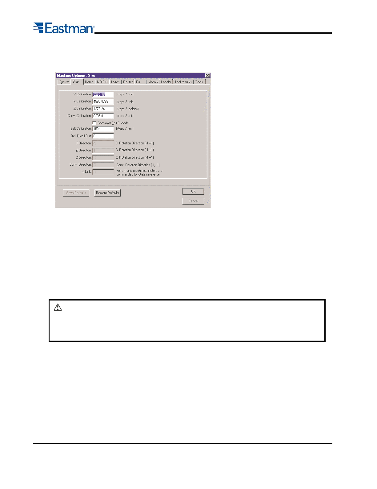
n) Click on OPTIONS then MACHINE in the menu and open up the SIZE tab. Enter the average number
of counts/cm in the "Belt Calibration" box.
o) Open up a file and click on the CUT icon for the new data to take effect.
Fine Tuning Secondary Conveyor Encoder for Long Length Pieces
The secondary conveyor encoder is an option which increases the cutting accuracy in the X direction of
the conveyor. The encoder tracks actual cutting belt movement in order to compensate for initial slack in
the link belt or slip in the cutting belt. This calibration procedure fine tunes the calibration number calculated in step 4, when cutting long pieces greater than 10 ft. If your machine does not have a secondary
encoder function you can skip this step.
Caution The Secondary encoder calibration should be performed when the belt or
any rollers are replaced. Periodically checking the encoder calibration will
insure the cutting accuracy.
a) Create a cut file with a long cut piece of approximately the same length as your longest piece. (Mini-
mum of about 12 meters (40 Feet).
b) Cut the file using paper or a non stretch material. (It is important to use a material that does not
stretch so that material stretch does not effect the calculations.)
c) Divide the required piece length from the cut file with the actual measured piece length. This number
will be greater than 1 if the piece was short and larger than 1 if the piece was long.
Example:
Required Length - 40' (480 in)
Actual Length - 40' 1-1/2" (481.5 in)
26
480 in / 481.5 in = 0.9969
Form E-526

d) Click on OPTIONS then MACHINE in the menu and open up the SIZE tab. Multiple the "X Calibration"
number by you calculated correction and enter the new number.. Then multiply the "Belt Calibration"
number by the calculated correction and enter the new number.
e) Repeat steps (b) through (d) until the overall length is within the machine tolerances.
Form E-526
27
Size Calibration
The size calibration ensures that the machine will cut parts to the correct size specified by the CMD file. This
calibration is important to make sure that the cut pieces are cut to the correct dimensions. The calibration
must be performed when the cutting machine is first installed, when a new tool head or new tool mount is
installed, or following any disassembly of cutting machine drive components.
28
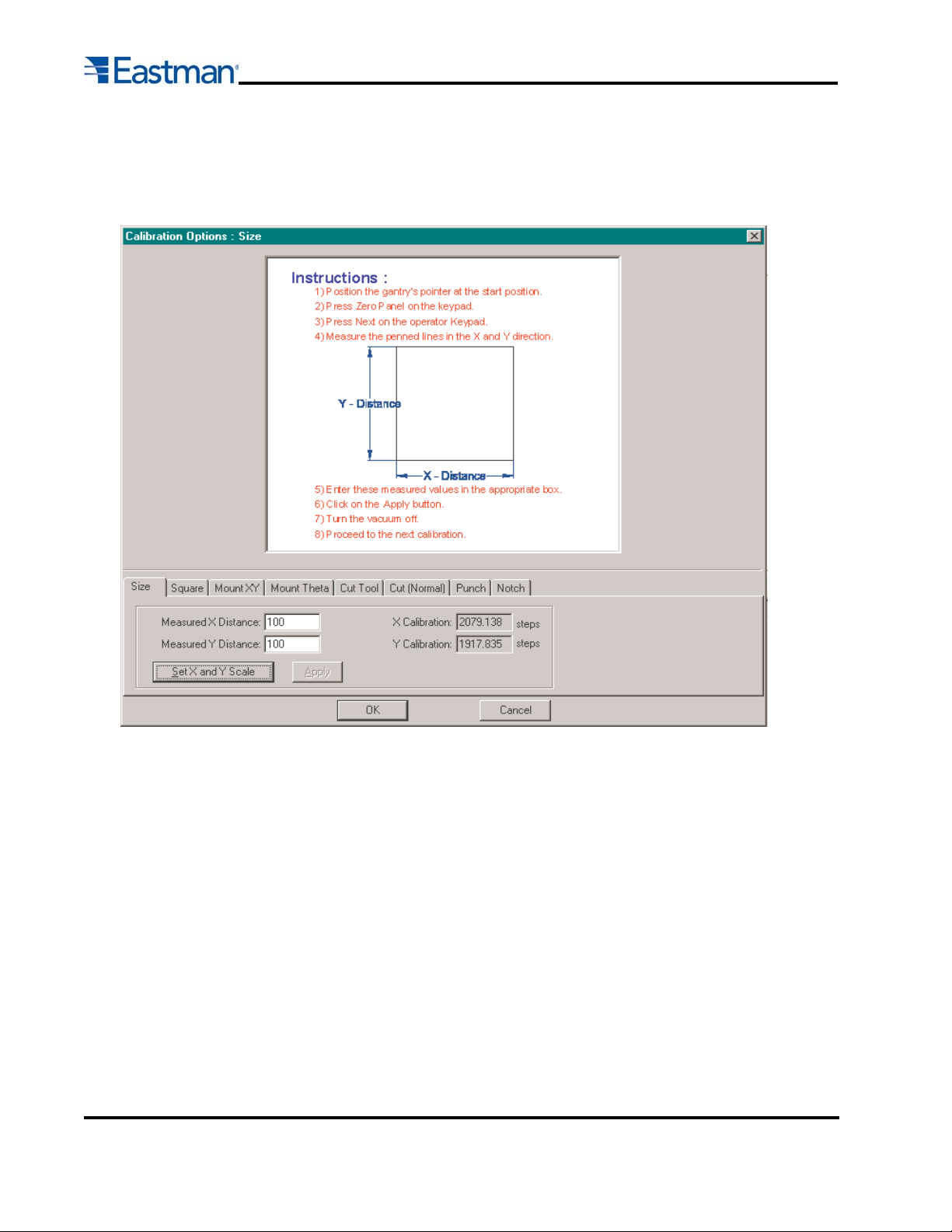
Size Calibration Procedure:
a) Open the Easicut 2000 software.
b) On the menu bar click on Option/Calibration and select the “Size” tab on the calibration screen.
c) Press the “Set X and Y Scale” button to load the Calibration test.
d) Layout a sheet of paper about 1.2 x 1.2 meters onto the cutting surface and apply vacuum.
e) Line the laser pointer to the lower left corner of the piece of paper and press the ZERO PANEL
button on the UIT.
f) Press the NEXT button on the UIT and let the machine run through the calibration. The machine
will pen a 1-meter by 1-meter square onto the sheet of paper.
g) Using a measuring tape, measure the length of the penned lines in both the X and Y direction,
these should measure 100.00 cm (39.370 inches). If the lines do not measure this value, enter
the measured value into the software in the correct box and click on the “Apply” button.
h) Continue with steps (d) through (g) until both the X and Y measurements are correct.
i) Press APPLY then OK to save the new values to the machine.ini file.
Form E-526
 Loading...