

Eastman Eagle C3 Parts List


Table of Contents
General Safety Precautions .......................................... 3
Safety Information .......................................................... 3
Safety Zones and Stop Devices ....................................... 4
Eagle C3 ...........................................................................5
Familiarization...................................................................5
Gantry Assembly ..............................................................6
Operator Side Stop Disc & Cover Assembly.....................7
Non-Operator Side Stop Disc & Cover Assembly .............8
Control Panel Assembly ....................................................9
Operator Side Frame Assembly......................................10
Non-Operator Side Frame Assembly ..............................12
Main Tube Assembly.......................................................14
Thick Wall Main Tube Assembly Only............................15
Gantry Electronics Assembly .........................................16
Y -Car Assembly With Cover............................................17
Y-Car Assembly ..............................................................18
Electronics Tray Assembly.............................................20
Electronics Package Assembly ......................................21
Cover For Tool Head Assembly.......................................22
HD T ool Head ..................................................................23
Pen Lift Assembly...........................................................24
Combo Tool Head, Hd+Fiber Assembly ..........................25
Optional: Fiber Tool Head Assembly...............................26
Conveyor Assembly ........................................................27
E-Chain Tray, Kit.............................................................28
T ake-On Conveyor Assembly ..........................................29
Rack & Rail Assembly ....................................................31
Vaccum Box Assembly ...................................................32
Drive End Conveyor Assembly ........................................33
Rectangular Riser............................................................34
Conveyor Asm .................................................................35
Control Cabinet ...............................................................37
Drive Chain Tension Assembly........................................39
Stiffner Assembly ............................................................40
Steer Glide Assembly .....................................................41
Steer Glide Sub Assembly 1...........................................42
Steer Glide Sub Assembly 2...........................................42
Steer Glide Sub Assembly 3...........................................43
Steer Glide Sub Assembly 4...........................................44
Steer Glide Sub Assembly 5...........................................44
4' Frame Assembly .........................................................45
4' Frame Assembly, W/Belt Car ......................................46
4' Frame Assembly, No Vac. Cabl ..................................47
S-Roller Assembly W/Uprights .......................................48
S-Roller/Paper/Plastic Roll Holder ..................................49
3-Spindle T ool Head ........................................................50
Kit, Light Curtain, Op & Non -Op ....................................51
Dual Airbrush...................................................................52
Single Airbrush ................................................................53
Ink Bottle Assembly........................................................53
Feed S-Roller Assembly Conveyor .................................54
Pressure Hold (Light) Assembly Conveyor .....................5 5
E-Stop/Jog Box Assembly,Take Off ................................56
E-Stop/Jog Box Assembly,Take On ................................57
Notes...............................................................................58
Service Record ................................................................59
Technical Data.................................................................60
IMPORTANT
The purchaser must instruct all operators on the proper use of this equipment. All standard industrial safety measures
and equipment should be provided to protect the operator. Operators must be cautioned that improper or careless
use of this equipment may cause personal injury. If you do not have qualified operators to instruct new persons,
contact your EASTMAN sales representative or EASTMAN factory direct.
Electrical connections and servicing to this equipment should be made by a qualified electrician who is familiar with
applicable codes and regulations. Disconnect this equipment from electrical power source before proceeding with
any disassembly for adjustment or repair.
Your Eastman EagleC3 is designed to operate at a high rate speed. All personnel should be instructed to wear safety
glasses and stand well clear of the EagleC3 when in operation.
2
Form E-543

Safety Information
Throughout this manual, safety information is presented by
the use of the terms WARNING, CAUTION, ELECTRICAL
HAZARD, and NOTE. These terms have the following meanings:
WARNING
A warning contains critical information regarding
potential safety hazards that can occur during proper
use or misuse of the machine. Failure to follow these
procedures may result in serious personal injury to
the user.
CAUTION
A caution contains instructions for the use or maintenance of the machine. Failure to follow these procedures may result in damage to the machine.
ELECTRICAL HAZARD
An electrical hazard calls attention to a procedure,
practice, or the like, which, if not correctly performed
or adhered to, could result in personal injury. Do
not proceed beyond an Electrical Hazard.
Supplementary information may be given in a Note.
Safety and Indemnification
During the life of the machine, the purchaser agrees
to provide to all machine users (including its own
employees and independent contractors) all relevant
safety information, including warning labels and instruction manuals. The purchaser also agrees to
maintain the safety features and working condition
of the machine, and to adequately train all users in
the safe use and maintenance of the machine. The
purchaser agrees to defend, protect, indemnify, and
hold Eastman Machine Company and its subsidiaries harmless from and against all claims, losses,
expenses, damages, and liabilities to the extent
that they have been caused by the purchaser’s failure to comply with the terms and instructions of
this manual.
General Safety Precautions
WARNING
• This machine is equipped with very sharp and dangerous tools. Keep hands, arms, and hair away from
the cutting area and drive system at all times. Safety
gloves, glasses, and appropriate clothing may prevent serious personal injuries.
• Disconnect the power supply to the machine when
it is not in use or during routine maintenance, including cleaning and lubrication.
• The purchaser must instruct all operators in the
proper use of the machine according to the instructions in this manual. This training must include instruction on the potential safety hazards arising from
the use or misuse of the machine. In addition to
such training, the purchaser should provide written
work instructions as necessary to ensure correct
use of the machine for specific cutting and spreading applications.
• Do not modify this machine or disable safety features. Unauthorized modification may result in serious personal injuries to the user. Electrical connections to this machine must be made by a qualified electrician familiar with applicable codes and
regulations.
• Safety labels must be kept clean and legible at
all times. Call the Eastman Machine factory to
order replacement labels.
Form E-543
3
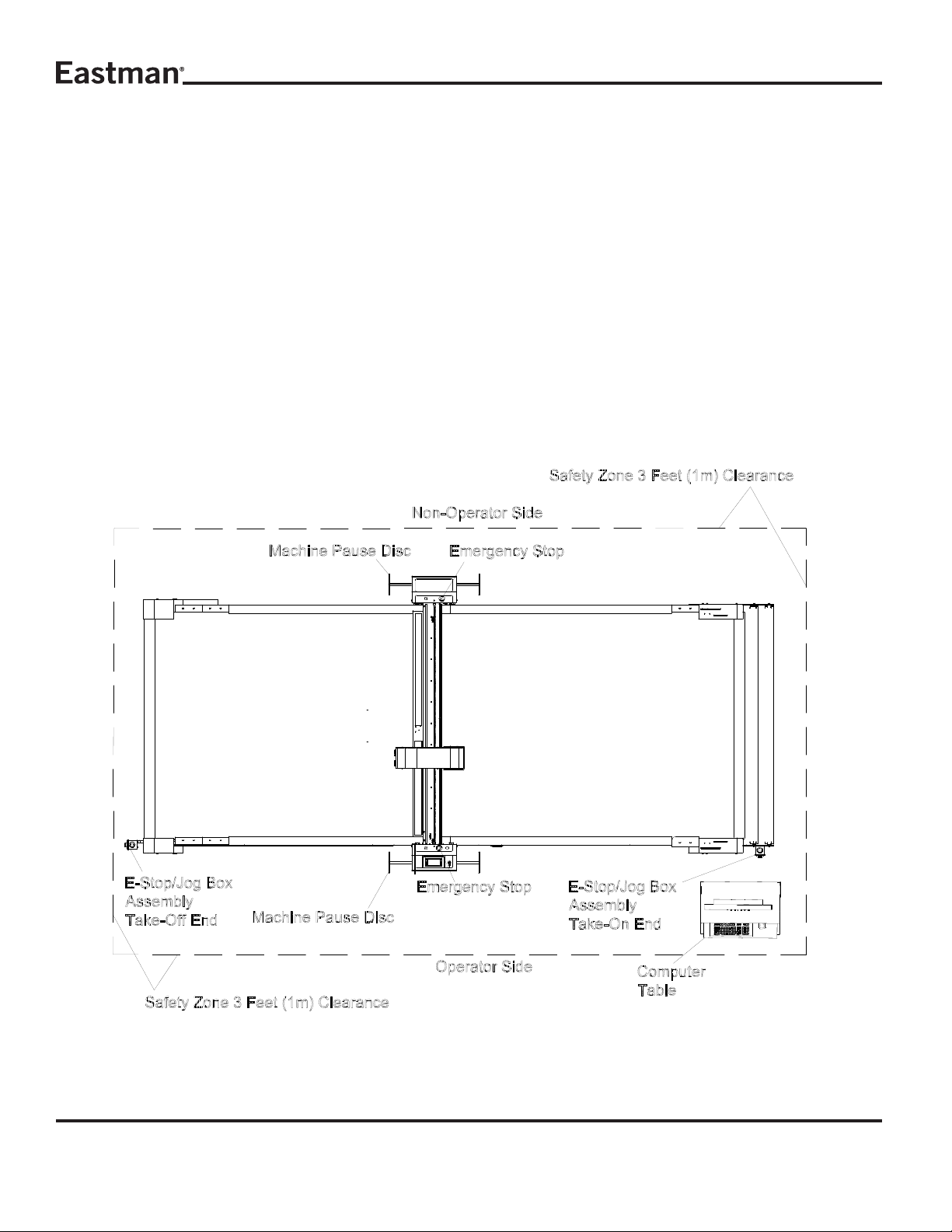
Safety Zones and Stop Devices
Pause Buttons/Disc
The yellow buttons above the control panel and on the
non-operator side of the gantry as well as the pause
discs on each side of the gantry will pause the
machine. Activating either the button or the pause
disc will execute a controlled stop of the plotter, with
the machine remaining fully powered. After releasing
the pause button or resetting the pause discs and
pressing NEXT on the UIT keypad, the cutter will
resume cutting the work in progress. Pressing
ABORT will cancel the job.
Emergency Stop Buttons
There are red Emergency Stop buttons located on
each side of the gantry as well as on the operator
side right and left ends of the table. Pressing any of
the Emergency Stop buttons will execute a controlled
stop of the gantry before cutting all power to the
motors and e-box. To release an Emergency Stop
condition, pull out the Stop button hit the ABORT key
on the UIT keypad. The table must be re-homed by
pressing the ZERO T ABLE button before restarting
the cutter. Emergency stop mats are also available
as an option.
4
Form E-543
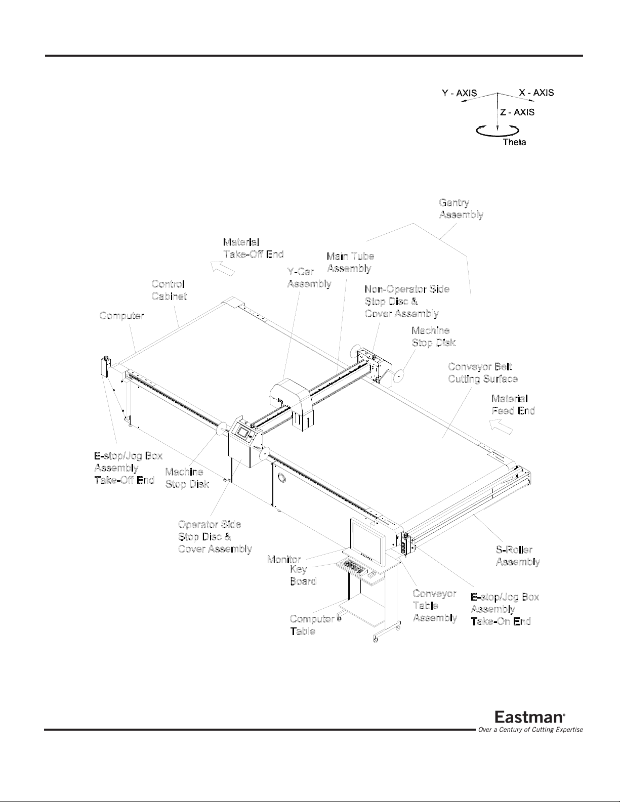
Eagle C3
Familiarization
Form E-543
5
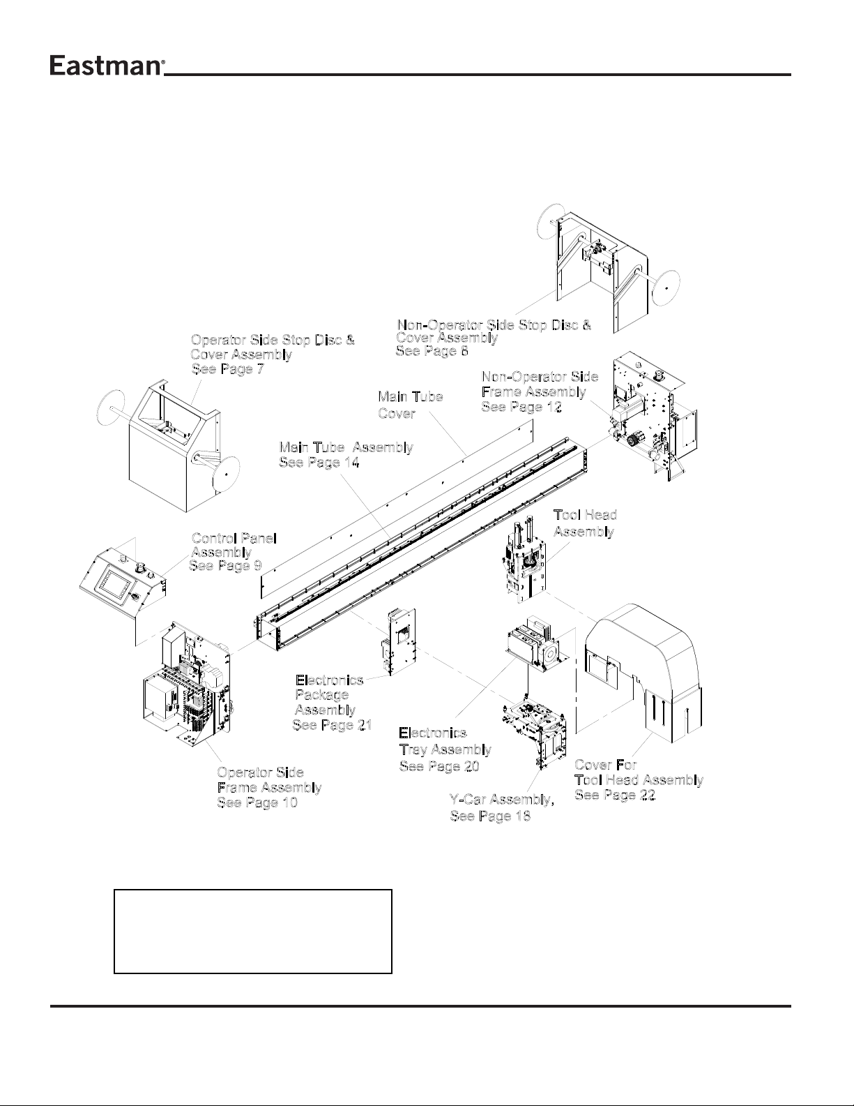
Gantry Assembly
68-26296-MS
Item numbers are for reference only.
Please Specify PART NUMBER when
ordering replacement parts.
6
Form E-543
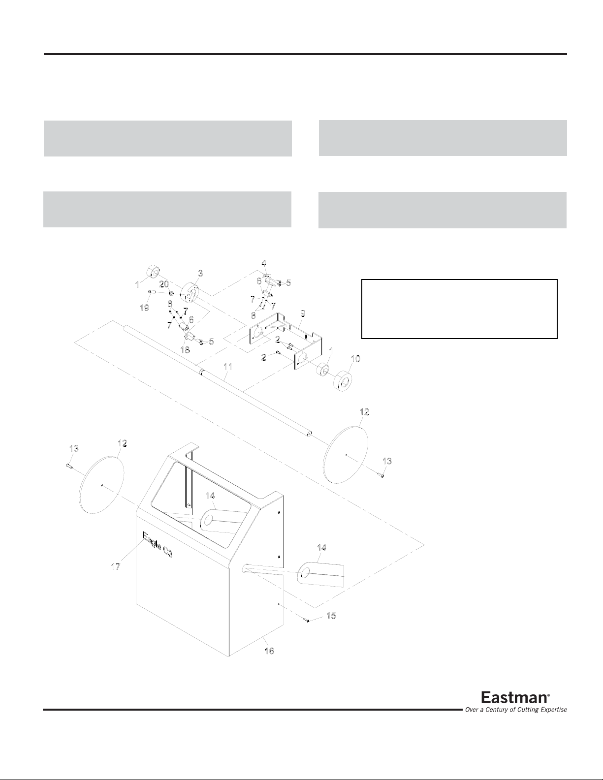
Operator Side Stop Disc & Cover Assembly
ITEM P ART No. DESCRIPTION QTY
1 67-26311 Self Align Bearing 2
2 333-102-8 Scr. Hex. Skt.Btn. #10-32 x 1/2 6
3 54-26422 Bearing & Switch Mount, Stop 1
4 54-26426 Switch Bracket,Stop Disk Assy 1
5 333-93-6 #8-32 x 3/8" Button Head Cap 4
6 11-1193 Switch, Limit 2
7 404-040 W asher, Ext.Tooth,#4, .123 I.D. 4
8 333-81-10 #4-40 U.N.C x 1/2 Lg B.H.C.S 4
9 54-27241 Pause Paddle Bracket 1
ITEM P ART No. DESCRIPTION QT Y
10 54-26421 Bearing Mount 1
1 1 54-27240 Pause Paddle Rod 1
12 54-26419 Disk, Stop Disk Assembly 2
13 333-34-12 Scr. Hex. Skt. Btn. 1/4-20 x 3/4 2
14 54-27249 Gantry Cover Gasket 2
15 333-93-12 S.S.B.H.S #8-32 x 3/4" Lg 6
16 67-26593 Gantry End Cover 1
17 91-26003 Decal, Medium Eastman 1
18 54-27447 Secondary Pause Switch
Bracket 1
19 9078-003 Plunger Spring 1
20 206-38 Nut, Jam Hex 3/8-16 1
Item numbers are for reference only.
Please Specify PART NUMBER when
ordering replacement parts.
Form E-543
7
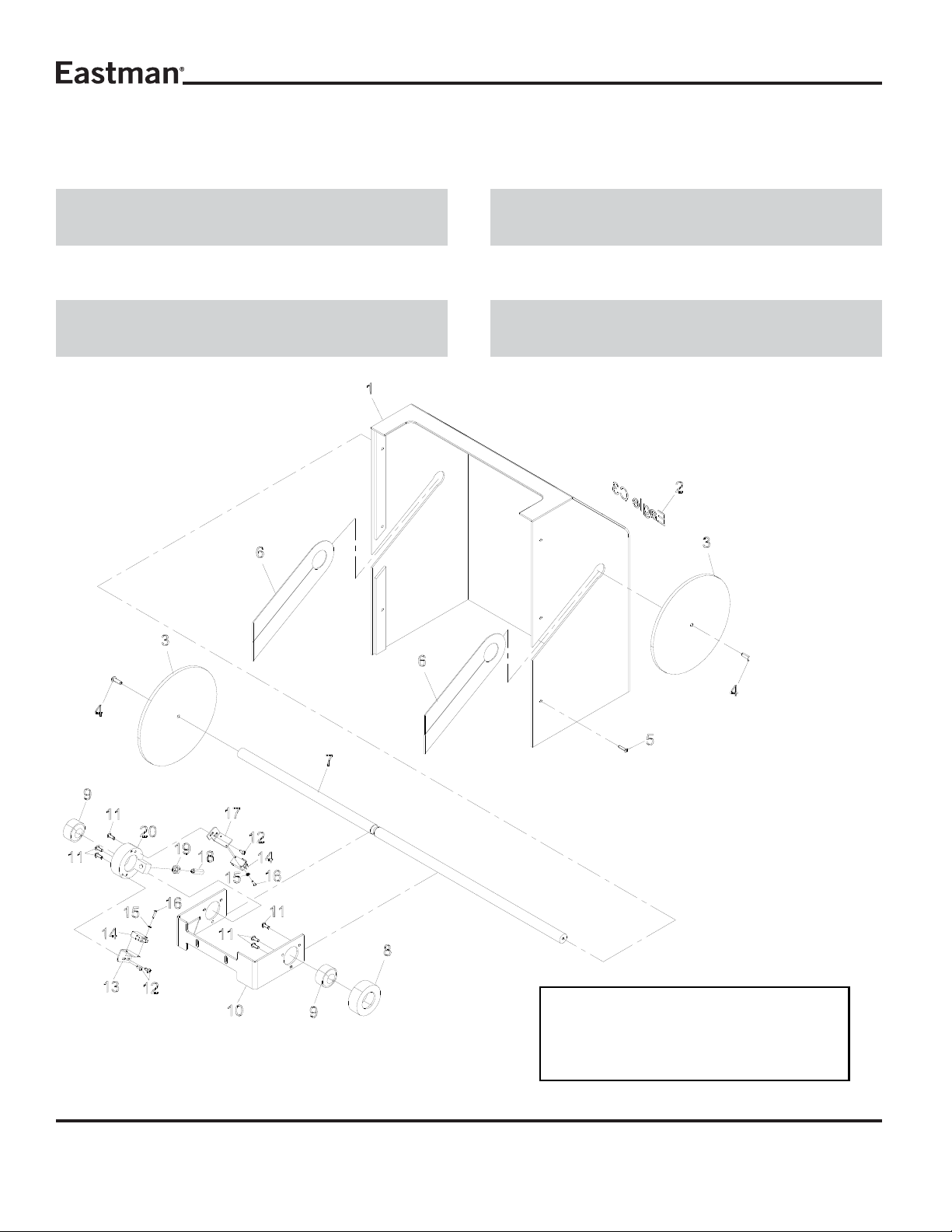
Non-Operator Side Stop Disc & Cover Assembly
ITEM P ART No. DESCRIPTION QTY
1 67-26593 Gantry End Cover 1
2 91-26003 Decal, Medium Eastman 1
3 54-26419 Disk, Stop Disk Assembly 2
4 333-34-12 Scr. Hex. Skt. Btn.1/4-20 x 3/4 2
5 333-93-12 S.S.B.H.S #8-32 x 3/4" Lg 6
6 54-27249 Gantry Cover Gasket 2
7 54-27240 Pause Paddle Rod 1
8 54-26421 Bearing Mount 1
9 67-26311 Self Align Bearing 2
10 54-27241 Pause Paddle Bracket 1
ITEM P ART No. DESCRIPTION QTY
1 1 433-102-8 Scr. Hex. Skt.Btn.#10-32 x 1/2 6
12 333-93-6 #8-32 x 3/8" Button Head Cap 4
13 54-26426 Switch Bracket,Stop Disk Assy 1
14 11-1193 Switch, Limit 2
15 404-040 W asher, Ext. Tooth,#4, .123 I.D.4
16 333-81-10 #4-40 U.N.C x 1/2 Lg B.H.C.S 4
17 54-27447 Secondary Pause Switch
Bracket 1
18 9078-003 Plunger Spring 1
19 206-38 Nut, Jam Hex 3/8-16 1
20 54-26422 Bearing & Switch Mount, Stop 1
Item numbers are for reference only.
Please Specify PART NUMBER when
ordering replacement parts.
8
Form E-543
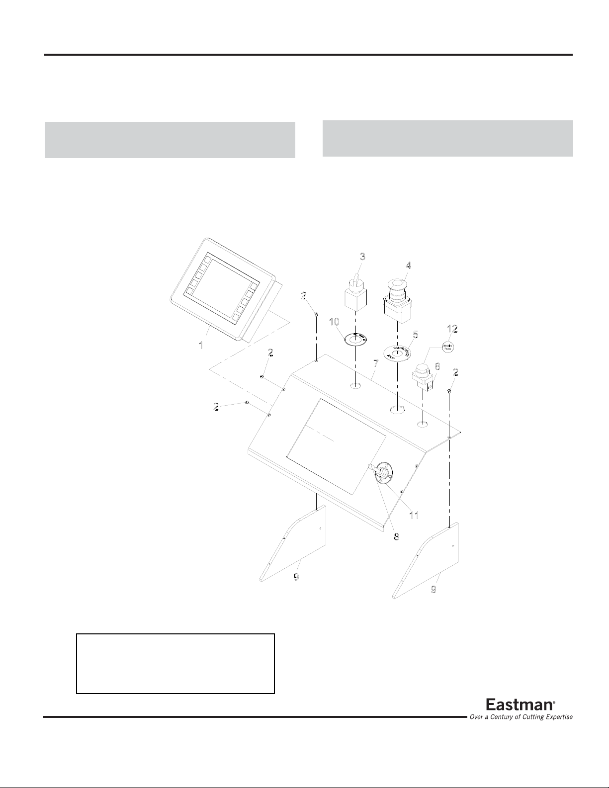
Control Panel Assembly
ITEM P ART No. DESCRIPTION QTY
1 31-26441 T ouch Screen Uit, Programmed 1
2 333-86-4 #6-32 x 1/4" Button Head Cap 6
3 31-26331 Green Selector Switch 1
4 31-26012 Switch Keylock, Spst 1
5 91-26011 Decal,"Emergency Stop" 1
6 31-26307 Y ellow Push Button 1
ITEM P ART No. DESCRIPTION QTY
7 67-26594 Uit Panel, Control 1
8 31-12947 Joystick, 4 Position, 4 No. Co. 1
9 54-27239 Uit Brace 2
10 91-26075 Decal, Tool On/Off 1
1 1 91-26076 Decal joystik Directions 1
12 91-26041 Decal, Button Labels, Router 1
Item numbers are for reference only.
Please Specify PART NUMBER when
ordering replacement parts.
Form E-543
9
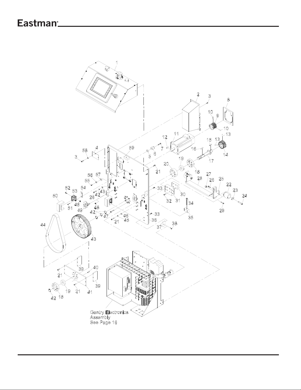
Operator Side Frame Assembly
10
Form E-543

ITEM P ART No. DESCRIPTION QTY
1 -------------- Control Panel Assembly 1
2 54-27558 E-Chain Shield, Gantry Plate 1
3 335-86-6 Scr. Skt. Hd. Cap #6-32 x 3/8 8
4 54-27559 Shield, Gantry Bearing 2
5 54-26598 Mount, Shock Absorber 1
6 67-26402 Rubber Bumper 1
7 335-93-14 Scr. Skt. Hd. Cap #8-32 x 7/8 7
8 54-26019 Motor Plate 1
9 67-26712 Motor Pulley 1
10 342-93-4 Set Screw #8-32 x 1/4 2
1 1 31-26436 X-Axis Motor 1
12 54-26985 Key, Drive Motor To
Gear Reducer 1
13 342-102-5 Set Screw #10-32 x 5/16 2
14 54-26295 Spur Gear , "X"-Axis 1
15 9063-010 Key 3/16 x 3/16 x .734 1
16 9063-104 Key, Flt. Sq. Ends
.1865 x .188 x .859 1
17 54-D0276 Shaft, Driven 1
18 54-D0019 Bearing Housing 2
19 67-12984 Bearing 2
20 54-LC095 Shim Bearing Housing 1
21 335-93-8 Scr. Skt. Hd. Cap #8-32 x 1/2 10
22 AD-12619 Bumper Stop 1
23 335-36-20 Scr. Skt. Hd. Cap
5/16-18 x 1 &1 /4 2
24 410-36 Washer, Flt. 5/16 2
25 54-27207 Bumper Block 2
26 335-102-10 Scr. Skt. Hd. Cap #10-32 x 5/8 6
27 205-36 Nut, Heavy Hex 5/16-18 2
28 54-27208 Bumper Connector Block 1
29 335-102-12 Scr. Skt. Hd. Cap #10-32 x 3/4 12
30 67-12983 Block Thk 2
31 54-2711 0 Support, Op-Side Bearing 2
32 335-M4-12 Scr. Skt.Hd.Metric M4 x 12mm 8
33 335-86-6 Scr. Skt. Hd. Cap #6-32 x 3/8 8
ITEM P ART No. DESCRIPTION QTY
34 335-34-32 Scr. Skt. Hd. Cap 1/4-20 x 2 2
35 54-2711 3 Backlash Adjuster 2
36 54-27111 Plate, Op-Side 1
37 54-C0306 Cover Clips 6
38 333-86-8 #6-32 x 1/2" Button Head Cap 2
39 54-D0485 X Drive S tandoff 2
40 332-102-10 Scr. Skt. Flt. Hd. Cap.
#10-32 x 5/8 8
41 54-D0022 X Shaft Support 1
42 67-D0216 Snap Ring 3/4 4
43 67-02963 Belt, Htd 800-5M-25 1
44 54-D0065 Pulley 112 Tooth 1
45 402-010 W asher, Lock #10 8
46 410-010 W asher, Flt. #10 8
47 332-102-20 #10-32 x 1 1/4" Flat
Socket Head Cap 8
48 211-93 Nut, Elastic Hex Light #8-32 6
49 31-26377 X Axis Standalone Amp-220 Vac2
50 54-27105 Hinge Secure Plate 2
51 335-86-10 Scr. Skt. Hd. Cap #6-32 x 5/8 4
52 333-93-8 Scr. Hex. Skt. Btn. #8-32 x 1/2 4
53 67-26571 Hinge, Adjustable Friction 2
54 54-27104 Hinge Spacer Plate 2
55 333-86-6 Scr. Hex. Skt. Btn. #6-32 x 3/8 4
56 402-34 Washer, Lock 1/4 4
57 410-34 Washer, Flt. 1/4 4
58 402-060 W asher, Lock #6 4
59 54-27244 Fastener Block 1
Form E-543
Item numbers are for reference only.
Please Specify PART NUMBER when
ordering replacement parts.
11
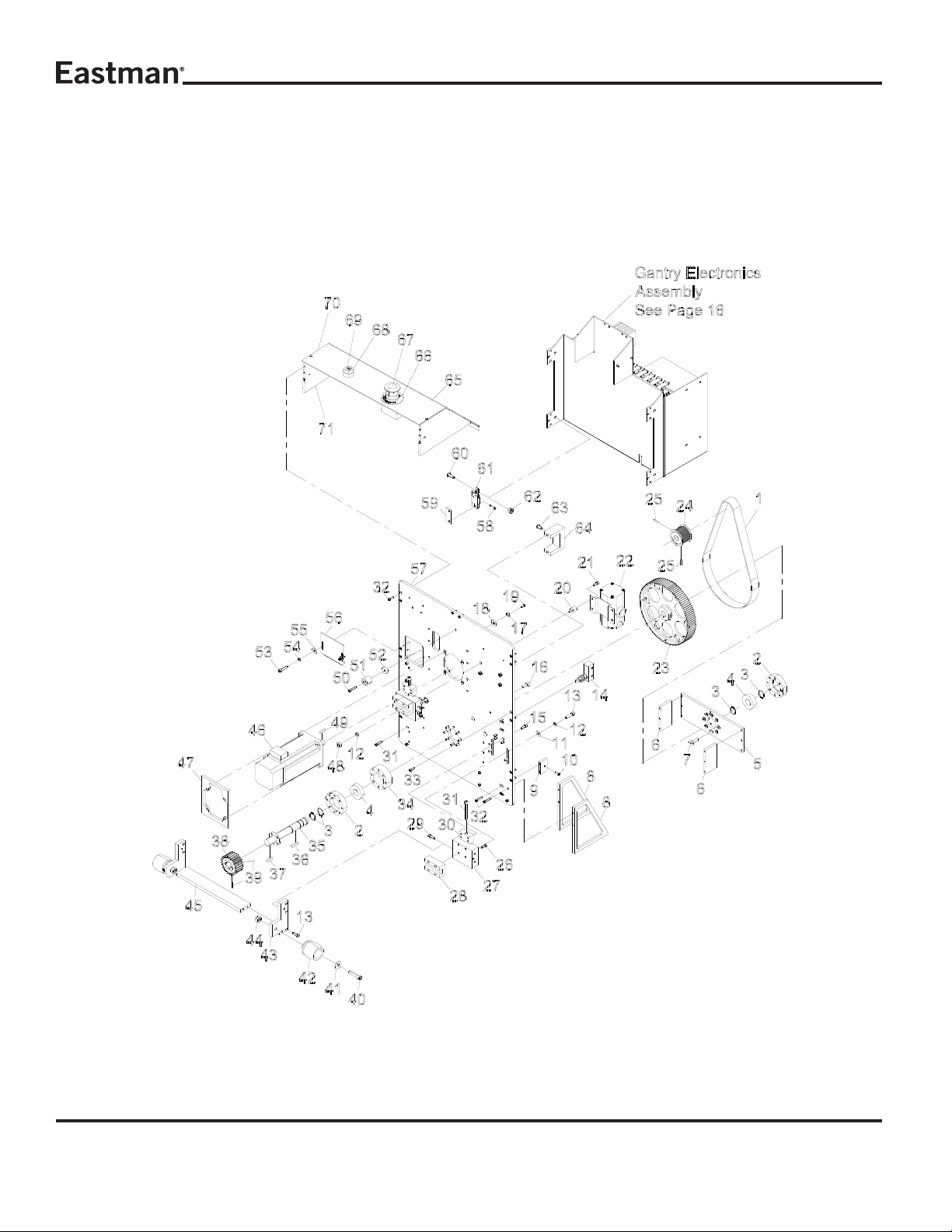
Non-Operator Side Frame Assembly
12
Form E-543

ITEM P ART No. DESCRIPTION QTY
1 67-02963-2 Belt, Htd 800-5M-25 1
2 54-D0019 Bearing Housing 2
3 67-D0216 Snap Ring 3/4 4
4 67-12984 Bearing 2
5 54-D0022-2 X Shaft Support 2
6 54-D0485 X Drive S tandoff 2
7 332-102-10 Scr.Skt.Flt.Hd.Cap.#10-32 x 5/88
8 54-26694 E-Chain Mounting Bracket 2
9 54-C0306 Cover Clips 2
10 333-93-8 Scr.Hex.Skt.Btn. #8-32 x 1/2 4
1 1 410-010 W asher, Flt. #10 8
12 402-010 W asher, Lock #10 8
13 335-102-12 Scr. Skt. Hd. Cap #10-32 x 3/4 12
14 31-26377 Switch, Roller, 90-Deg, Spdt 2
15 335-102-9 Scr.Skt.Hd.Cap #10-32 x .5625 4
16 332-102-10 Scr.Skt.Flt.Hd.Cap.#10-32 x 5/816
17 402-34 Washer, Lock 1/4 4
18 410-34 Washer, Flt. 1/4 4
19 335-93-6 Scr.Hex. Skt. Btn. #6-32 x 3/8" 4
20 65-26024 Vibration Mount,10-32 Plate 8/31
21 335-102-8 Scr. Skt. Hd. Cap #10-32 x 1/2 4
22 27-20001 Regulator, Air Control 1
23 54-D0065 Pulley 112 Tooth 1
24 67-26712 Motor Pulley 1
25 342-93-4 Set Screw #8-32 x 1/4" 2
26 335-M4-12 Scr. Skt. Hd.Metric M4 x 12mm8
27 54-2711 0 Support, Op-Side Bearing 2
28 67-12983 Block Thk 2
29 335-102-10 Scr. Skt. Hd. Cap #10-32 x 5/8 6
30 54-2711 3 Backlash Adjuster 2
31 335-34-32 Scr. Skt. Hd. Cap 1/4-20 x 2 2
32 335-93-12 Scr. Skt. Hd. Cap #8-32 x 3/4 8
33 335-93-8 Scr. Skt. Hd. Cap #8-32 x 1/2 12
34 54-LC095 Shim Bearing Housing 1
35 54-D0276 Shaft, Driven 1
36 9063-104 Key, Flt. Sq. Ends
.1865 x .188 x .859 1
ITEM P ART No. DESCRIPTION QTY
37 9063-010 Key 3/16 x 3/16 x .734 1
38 54-26295 Spur Gear , "X"-Axis 1
39 342-102-5 Set Screw #10-32 x 5/16 2
40 335-36-20 Scr. Skt. Hd. Cap
5/16-18 x 1 &1 /4 2
41 410-36 Washer, Flt. 5/16 2
42 AD-12619 Bumper, S top 1
43 54-27207 Bumper Block 2
44 205-36 Nut, Heavy Hex 5/16-18 2
45 54-27208 Bumper Connector Block 1
46 31-26436 X-Axis Motor 1
47 54-26019 Motor Plate 1
48 202-93 Nut, Mach, Scr, Hex #8-32 6
49 54-26985 Key, Drive Motor To
Gear Reducer 1
50 335-93-14 Scr. Skt. Hd. Cap #8-32 x 7/8 1
51 67-26402 Rubber Bumper 1
52 54-26598 Mount, Shock Absorber 1
53 335-88-10 S.H.C.S. #6-40 x 3/4 2
54 402-060 W asher, Lock #6 2
55 410-060 W asher, Flat #6 2
56 54-27565 Gantry Cable Clamp Shield 2
57 54-2711 2 Plate, Non Operator side 1
58 335-86-10 Scr. Skt. Hd. Cap #6-32 x 5/8 4
59 54-27104 Hinge Spacer Plate 2
60 333-93-8 Scr. Hex. Skt. Btn. #8-32 x 1/2 4
61 67-26571 Hinge, Adjustable Friction 2
62 211-93 Nut, Elastic Hex Light #8-32 6
63 333-34-8 Scr. Hex. Skt. Btn 1/4-20 x 1/2 2
64 54-27105 Hinge Secure Plate 2
65 54-27242 Cover Panel 1
66 91-26011 Decal,"Emergency Stop" 1
67 31-26012 Red Push/Pull Switch 1
68 31-26307 Y ellow Push Button 1
69 91-26041 Decal, Button Labels, Router 1
70 54-27242 Cover Panel 1
71 54-27329 Uit Brace 2
Form E-543
Item numbers are for reference only.
Please Specify PART NUMBER when
ordering replacement parts.
13
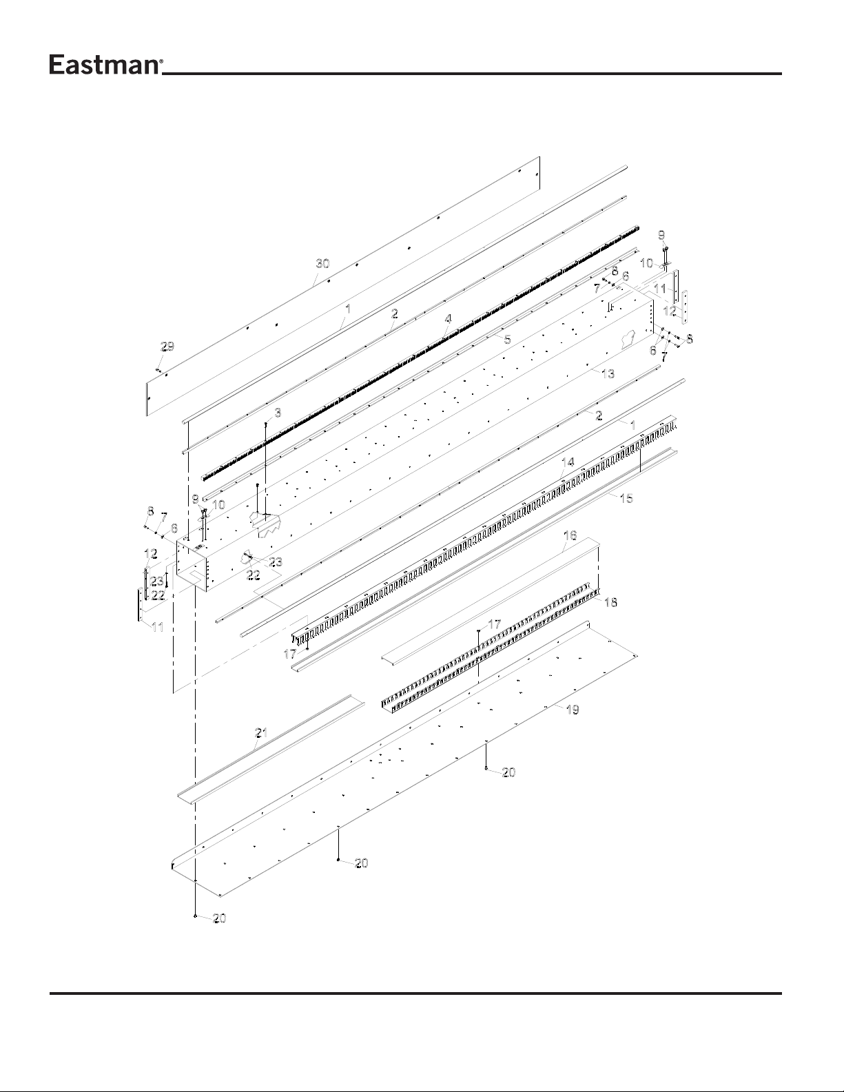
Main Tube Assembly
68-26284-MS
14
Form E-543
ITEM P ART No. DESCRIPTION QTY
1 67-CO219 Linear Rail, 1/2" Dia, 90" Leng 2
2 67-C0220 Low Support, 1/2" Rail 2
3 333-86-12 Scr. Hex. Skt.Btn. #6-32 x 3/4"30
4 67-12990 Gear Rack, 96" 20p 1
5 54-C0411 Y-Rack Support, 96" Fabric 1
6 410-010 W asher, Flt. #10 14
7 402-010 W asher, Lock #10 14
8 335-102-8 Scr.Skt.Hd.Cap #10-32 x 3/8 14
9 332-102-6 Scr.Skt.Flt.Hd.Cp.#10-32 x 3/2 6
10 54-26807 Cam 3
1 1 54-C0305-5 Main Tube Mtg Insert 2
12 54-C0305-6 Main Tube Mtg Insert 2
13 54-27171 Gantry Main Tube 1
14 70-26001 Duct, Wiring,
1" Wide x 1.5" High 1
15 67-02634 Conduit Top 1" 1
16 70-26005 Cover, Wiring Duct, 2" Wide 1
17 203-102 Nut, Machine Screw #10-32 15
18 70-26006 Duct, Wiring,
2" Wide x 1" High 1
19 54-C0410 BelleyPan 1
20 333-102-4 Scr. Cap. Rd. Head Socket
#10-32 x .250 3 0
21 67-26181 Panduit Top, 2.5" Wide 1
22 335-86-12 #6-32 x 3/4" Socket Head Cap 46
23 402-060 W asher, Lock #6 46
24 67-C0220 Rail Support Top 2
ITEM P ART No. DESCRIPTION QTY
25 67-C0219-MS Linear Rail,1/2" Dia, 90" Leng 2
26 54-C0411-MS Y- Rack S up p o r t 1
27 335-86-12 Scr. Btn.Hd. Cap #6-32 x 3/4 A/R
28 402-060 W asher, Lock #6 A/R
29 333-102-6S Screw, Button Hd # 10-32 x 3/8 A/ R
30 54-27279-MS Cover, Main Tube 1
*MS - Machine Size
*A/R - As Required
Item numbers are for reference only.
Please Specify PART NUMBER when
ordering replacement parts.
Form E-543
Thick Wall Main Tube Assembly Only
15

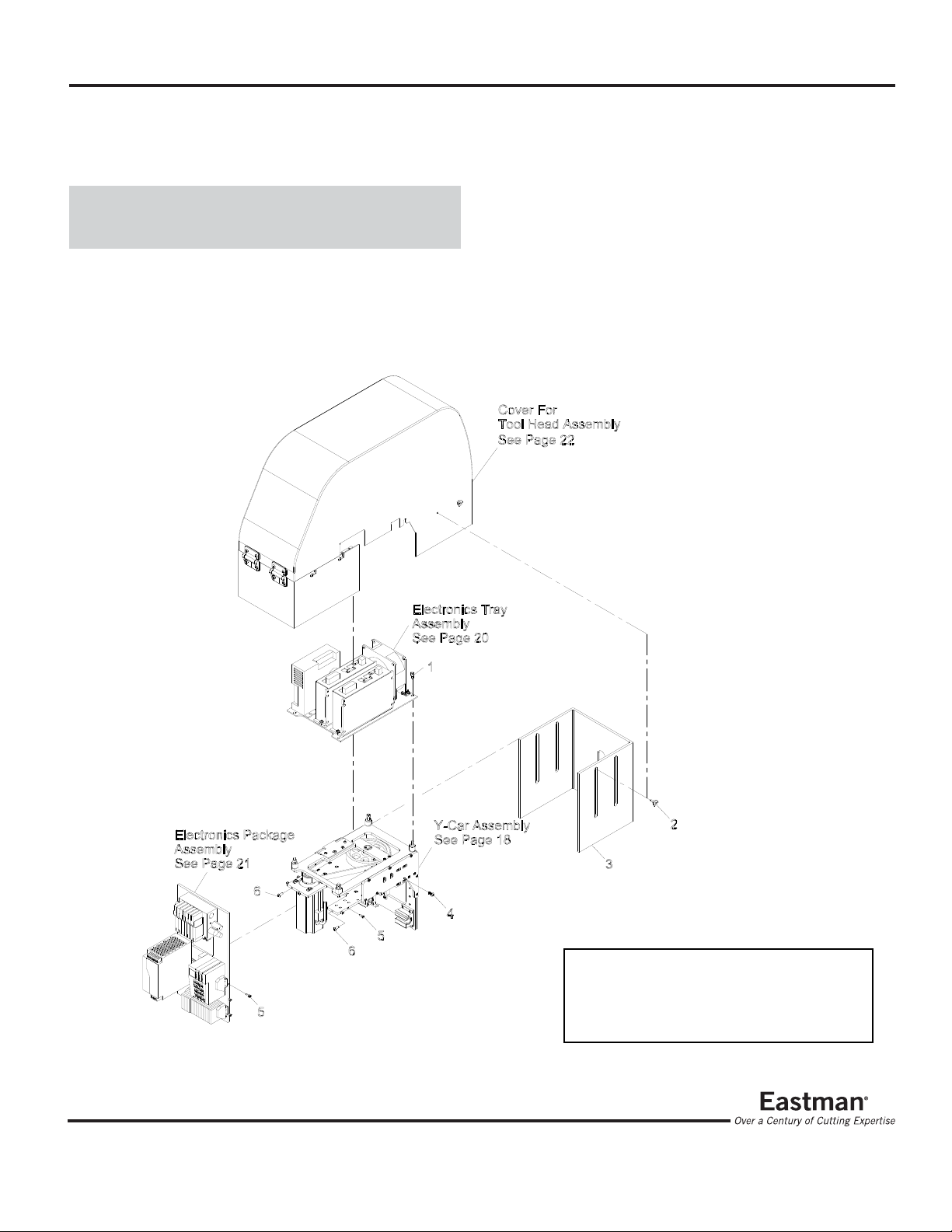
Gantry Electronics Assembly
ITEM P ART No. DESCRIPTION QTY
1 31-26376 Power Supply 24Vdc 2Amp 1
2 31-26414 T erminal end Clamps 4
3 211-93 Nut, Elastic Hex Light #8-32 13
4 31-00739 7" Terminal Mount 3
5 54-27107 Electronic Tray 1
6 70-26001 Duct, Wiring,
1" Wide x 1.5" High 3
7 31-26361 36 Screw Terminal Block 1
ITEM P ART No. DESCRIPTION QTY
8 31-26366 Slice I/O Network Adaptor 1
9 31-26367 Slice 8 Digital Input 2
10 31-26384 T erminal Blocks 20
1 1 31-26405 Ground Terminal Block 4
12 31-26377 X Axis Standalone Amp-220Vac 1
13 203-102 Nut, Machine Screw.#10-32 4
14 402-010 W asher, Lock.#10 4
15 335-102-8 Scr.Skt.Hd.Cap.#10-32 x 1/2 4
Item numbers are for reference only.
Please Specify PART NUMBER when
ordering replacement parts.
16
Form E-543
Y-Car Assembly With Cover
68-26315
ITEM P ART No. DESCRIPTION QTY
1 335-34-6 Scr.Skt.HD.Cap 1/4-20 x 3/8 4
2 67-26762 Steeped Screw 4
3 54-27297 T ool Guard 1
4 332-102-8s Button Soced Hd Screw 2
5 335-93-6 Scr.Skt.Hd.Cap 8-32 x 3/8 10
6 333-86-8 #6-32 x1/2" Button HeadCap 3
Form E-543
Item numbers are for reference only.
Please Specify PART NUMBER when
ordering replacement parts.
17
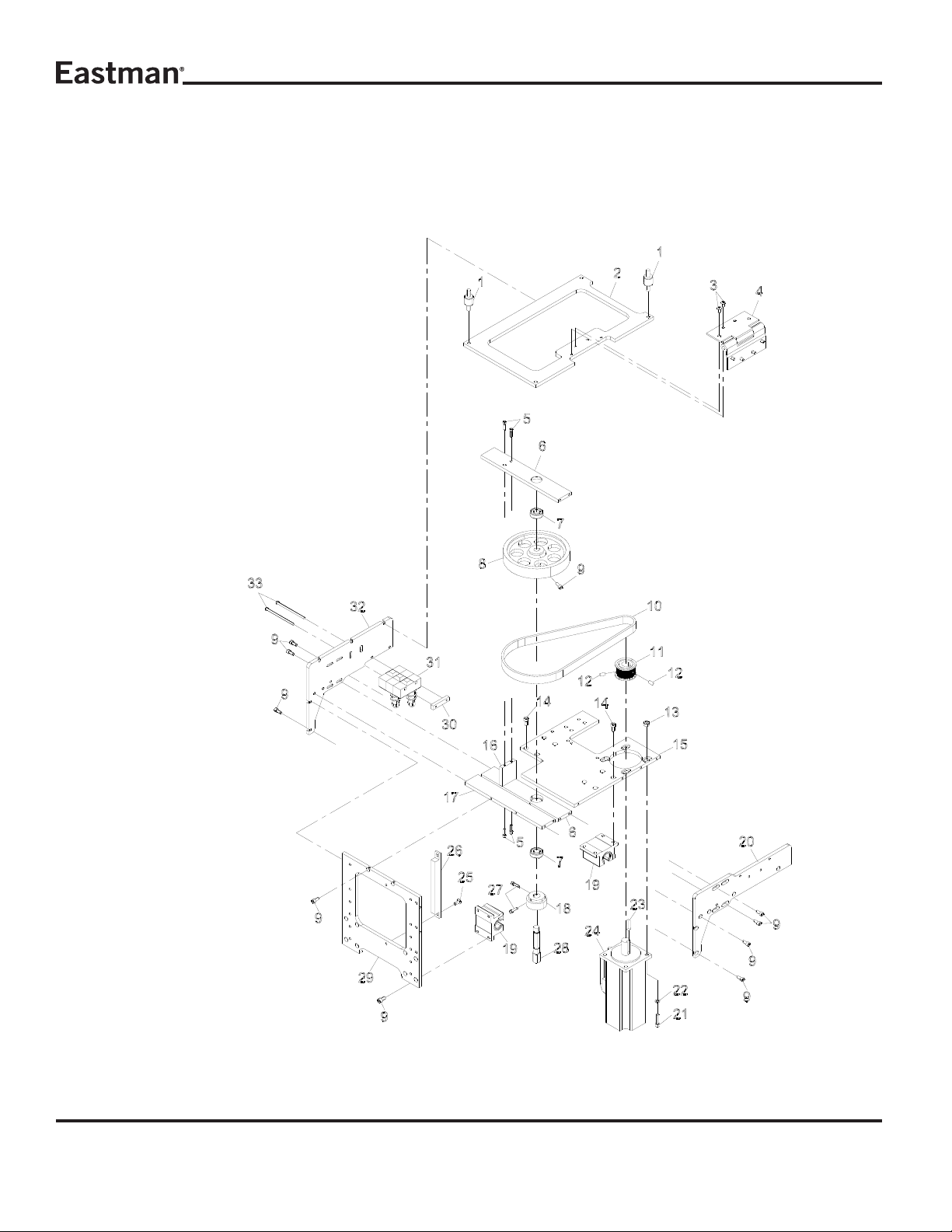
Y-Car Assembly
68-26316
18
Form E-543
 Loading...