

EASTMAN 629XS, 627XS Parts List
EASTMAN
®
CE Approved
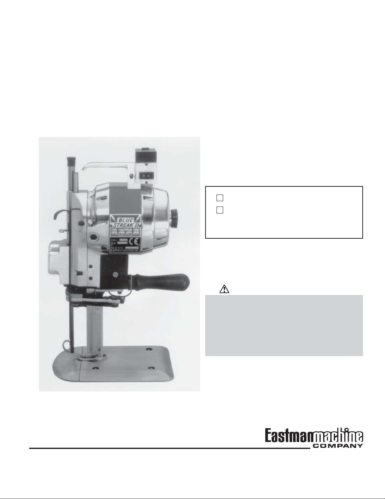
BLUE STREAK® II
CE Approved
Model 629XS Auto-Stop
BRUTE Model 627XS Auto-Stop
Instruction Manual
and Parts List
Blue Streak II Model 629XS Auto-Stop
Brute Model 627XS Auto-Stop
Serial # _____________________________
WARNING
This machine is equipped with a very sharp knife.
Keep hands, arms, and hair away from the knife
area at all times.
Misuse of this machine or failure to follow all safety
instructions on this machine and in the instruction
manual may result in serious personal injuries.
779 Washington St., Buffalo, N.Y. 14203-1396 U.S.A. • (716) 856-2200 • Fax (716) 856-1140 or (716) 856-2068
Website: www.EastmanCuts.com
Form C-1572

EASTMAN
Limited Warranty. Eastman warrants to the buyer that the Blue Streak II and Brute shall be free from
defects in materials or workmanship for a period of 180 days commencing on the date of invoice. Any goods
or parts claimed by the buyer to be defective must be returned to Eastman, freight charges prepaid, within
the 180–day warranty period. If Eastman determines that the goods or parts are defective in materials or
workmanship, Eastman's sole obligation under this warranty shall be, at Eastman's sole option, to repair or
replace the defective goods or parts or to provide to the buyer a credit equal to the portion of the purchase
price allocable to the defective goods or parts. This warranty shall not apply if defects are caused by
product misuse or neglect, if the machine has been altered or modified by the buyer, or if other than genuine
Eastman belts, emery wheels, knives or parts are used in the machine. THIS WARRANTY IS THE ONLY
WARRANTY APPLICABLE TO THIS PURCHASE. SELLER DISCLAIMS ALL OTHER WARRANTIES,
EXPRESS OR IMPLIED, INCLUDING, BUT NOT LIMITED TO, THE IMPLIED WARRANTIES OF MERCHANTABILITY AND FITNESS FOR A PARTICULAR PURPOSE.
Limitation of Liability. Eastman's liability to the buyer, and the buyer's remedies from Eastman, whether in
contract, negligence, tort, under any warranty or otherwise, shall be limited to the remedies provided in the
foregoing Limited Warranty. In no event shall Eastman have any responsibility or liability to the buyer for (a)
any special, indirect, incidental, or consequential damages, including, but not limited to, loss of use, revenue, or profit, even if Eastman has been advised of the possibility of such damages, or (b) any claim
against the buyer by any third party. The price stated for the product sold is a consideration for limiting
Eastman's liability.
Form C-1572

Table of Contents
Safety Information ........................................ 1
General Safety Precautions ..................................... 1
Operation ...................................................... 2
Initial Set Up ............................................................. 2
Operating Procedure ................................................ 3
Safety Considerations ................................................ 3
Starting the Machine .................................................. 4
Making a Cut .............................................................. 4
Turning Off the Machine ............................................. 4
Routine Maintenance ................................... 4
Care of the Machine ................................................. 4
Daily ........................................................................... 4
Twice Weekly .............................................................. 4
Weekly ....................................................................... 5
Lubrication ................................................................ 5
Daily ........................................................................... 5
Weekly ....................................................................... 5
Monthly....................................................................... 5
Sharpening the Knife ............................................... 5
Removing the Sharpener ........................................... 5
Adjusting the Belt Sharpener .................................. 7
Changing Sharpener Belts ......................................... 7
Adjusting Stabilizers for Central Alignment ................. 7
Checking the Sharpener Shoes .................................. 8
Checking the Extreme Down Position of the
Sharpener ............................................................ 8
Checking the Stop Screw on the Sharpener Shoe...... 9
Check the Width of the Bevel on the Knife .................. 9
Changing the Knife ..................................................... 9
®
Adjusting Bevel Bloc
Troubleshooting ..................................................... 14
Freeing Frozen Guides .......................................... 16
Shoes ................................ 11
Accessories ................................................ 16
Metal Mesh Gloves ................................................. 16
Ordering Details ....................................................... 17
Genuine Eastman Abrasive Belts ......................... 17
Ergo-Handle ............................................................ 18
Specialty Machines ................................................ 19
Plastic Master Model 627XSPM/629XSPM .............. 19
Micro Fog Model 627XSMF/629XSMF ..................... 19
Replacing the Rubber Driver Pulley ........................ 6
IMPORTANT
This manual contains instructions and part numbers for two
different machines: Brute Model 627XS and Blue Streak II
Model 629XS. If you contact Eastman Machine Company
for information or to order parts, always specify the machine name and model number.
If you are ordering electrical components, specify the voltage, frequency (Hz), and speed (RPM) of your machine.
You can find this information on a label attached to your
machine.
Illustrated Parts List ................................... 20
Exploded Parts Illustrations .................................. 20
Patents Statement
Some parts of this manual and the equipment it describes
are protected by the following U.S. patents: 5,178,232,
4,609,244, 5,111,582, 4,761,878, and D281,416. Other patents pending.
Trademarks Statement
The names Eastman, Uni-Safe, Blue Streak, and Bevel Bloc
are registered trademarks of the Eastman Machine Company.
Form C-1572
ii

EASTMAN
List of Figures
Figure 1. Operating Features ....................................... 2
Figure 2. Controls and Adjustments ............................ 3
Figure 3. Removing the Sharpener.............................. 6
Figure 4. Replacing the Rubber Driver Pulley .............. 6
Figure 5. Changing the Sharpener Belts ...................... 7
Figure 6. Adjusting the Stabilizers ............................... 7
Figure 7. Changing the Knife ....................................... 9
Figure 8. Available Eastman Knife Types ................... 10
Figure 9. Adjusting Bevel Bloc Shoes ........................ 11
Figure 10. Bevel Bloc Shoe Assembly ......................... 12
Figure 11. Maintenance Supplies ................................ 13
Figure 12. Electrical Configuration ............................... 15
Figure 13. Freeing Frozen Guides ............................... 16
Figure 14. Available Metal Mesh Glove Styles ............. 17
Figure 15. Eastman Abrasive Belts.............................. 17
Figure 16. Edges Produced by Different Belt Grits ...... 18
Figure 17. Ergo-Handle ............................................... 18
Figure 18. Plastic Master ............................................. 19
Figure 19. Micro Fog ................................................... 19
Figure 20. Exploded Assembly View ............................ 21
Figure 21. Single-Phase Motor Assembly
(Assembled View) ....................................... 22
Figure 22. Single Phase Motor Assembly
(Exploded View).......................................... 23
Figure 23. Three-Phase Motor Assembly
(Assembled View) ....................................... 24
Figure 24. Three-Phase Motor Assembly
(Exploded View).......................................... 25
Figure 25. Front Bearing Housing with Oiler
Assembly (Exploded View) ......................... 27
Figure 26. Sharpener Housing Assembly
(Assembled, Front View) ............................. 28
Figure 27. Sharpener Housing Assembly
(Exploded, Front View) ............................... 29
Figure 28. Sharpener Housing Assembly
(Assembled, Rear View) ............................. 30
Figure 29. Sharpener Housing Assembly
(Exploded, Rear View) ................................ 31
Figure 30. Lower Gear Bracket Assembly
(Assembled View) ....................................... 32
Figure 31. Lower Gear Bracket Assembly
(Exploded View).......................................... 33
Figure 32. Standard and Baseplate Assembly
(Assembled View) ....................................... 34
Figure 33. Standard and Baseplate Assembly
(Exploded View).......................................... 35
Figure 34. Removing a Worn Plate Roller Shell ........... 35
ii
Form C-1572

Safety Information
Throughout this manual, safety information is presented
by use of the terms Warning, Caution, and Note. These
terms have the following meanings:
WARNING
A warning contains critical information regarding potential safety hazards that can occur during proper use or
misuse of the machine. Failure to follow these procedures may result in serious personal injury to the user.
CAUTION
A caution contains instructions for the use or maintenance of the machine. Failure to follow these procedures may result in damage to the machine.
Supplementary information may be given in a Note.
General Safety Precautions
WARNING
• This machine is equipped with a very sharp and dangerous knife. Keep hands, arms, and hair away from
the knife area at all times. When the machine is not
in use, keep the pressure foot knife guard lowered
and locked at all times. Safety gloves and glasses
and appropriate clothing may prevent serious personal injuries.
• Disconnect the power supply from the machine when
it is not in use or during routine maintenance, including lubrication.
• The purchaser must ensure that the electrical power
supply line complies with all the local electrical code,
regulation.
• The purchaser must instruct all operators in the
proper use of the machine according to the instructions on the machine and in this manual. This training must include instruction on the potential safety
hazards arising from the use or misuse of the machine. In addition to such training, the purchaser
should provide written work instructions as necessary to ensure correct use of the machine for specific cutting applications.
Safety and Indemnification
During the life of the machine, the purchaser agrees to provide to all machine users (including its own employees and
independent contractors) all relevant safety information, including warning labels and instruction manuals. The purchaser also agrees to maintain the safety features and working condition of the machine, and to adequately train all
users in the safe use and maintenance of the machine.
The purchaser agrees to defend, protect, indemnify, and
hold Eastman Machine Company harmless from and
against all claims, losses, expenses, damages, and liabilities to the extent that they have been caused by the
purchaser’s failure to comply with the terms and instructions of this manual.
• The purchaser must provide appropriate safety measures and equipment as recommended in this
manual. Observe all statutory requirements concerning the use of hazardous machinery that apply to
your location.
• Do not modify this machine or disable safety features.
Unauthorized modification may result in serious personal injuries to the user. Electrical connections to
this machine must be made by a qualified electrician
familiar with applicable codes and regulations. To
prevent electrocution, a ground lead must be connected to terminal “E” on the attachment plug.
• This machine is intended ONLY for hand-held operation. Misuse of this machine or use of this machine as part of another machine may result in serious personal injuries to the user.
• Safety labels must be kept clean and legible at all
times. Call the Eastman Machine factory to order
replacement labels.
Form C-1572
1
EASTMAN
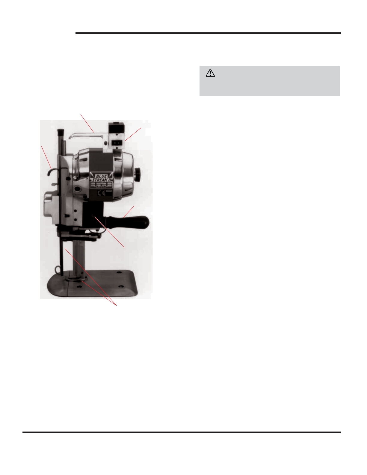
Operation
Before operating the machine, read these instructions carefully. Familiarize yourself with all the functions and adjustments of the machine.
Carrying Handle
Main Power
Pressure
Foot Lift
Handle
ON/OFF Switch
Auto-Stop
Operating Handle
Start Button
CAUTION
Operating this machine from an incorrect electrical
supply may damage it.
2. Check that the machine has been lubricated according
to the schedule listed in Routine Maintenance–Lubrica-
tion on page 5.
Note: At this time, carry out the full monthly lubrication
schedule on page 5.
3. Make sure that the sharpener is in the locked position.
To do this, push in the turning knob (Figure 2, F). While
depressing the turning knob, turn the machine over a
few revolutions by hand to see if the knife reciprocates
easily. If the knife does not move easily, the sharpener
may be in the unlocked position.
4. To lock the sharpener in place, lift the release lever
(Figure 2, D) and press the sharpener lever (Figure 2,
E) to release the sharpener. Raise the sharpener
bracket (Figure 2, S) by hand to lock it in place. Once
the sharpener is locked in place, you may disengage
the release lever and sharpener lever. Repeat step 3
to ensure that the sharpener is now locked. If not,
repeat this step.
Knife GuardPressure Foot
Figure 1. Operating Features
Initial Set Up
After the machine has been installed and before you use it
for the first time:
1. Check that the electrical supply current and voltage that
the machine is connected to are the same as stamped
on its name plate. For three-phase machines, also
check that the direction of rotation is correctly set by the
turning knob (Figure 2, F). Refer to the tag attached to
all three-phase machines for detailed instructions.
5. Visually inspect the blade to ensure that the top of the
knife is flush with the knife lockbolt (Figure 7, 1 on page
9) and that the knife is perpendicular to the baseplate.
If you need to adjust the alignment of the blade, see
section Changing the Knife on page 9.
6. Check that the main power switch is in the OFF position.
Then connect the attachment plug to the terminal block
on the machine.
7. Hold the operating handle and switch on the machine.
Press the start button and allow the blade to reach full
speed. If the blade is struggling, the sharpener is still
not in the locked position. If this is the case, turn off the
machine and do the following:
7.1 With your left hand, switch the on the machine.
Straddle the front of the sharpener with fingers and
thumb.
7.2 Press the bell crank release lever (Figure 2, H) to
disengage the sharpener mechanism from the motor.
2
Form C-1572
7.3 With your right hand, hold the operating handle
and press the start button. Allow the motor to gather
full speed and then release the release lever. This
automatically returns the sharpener to the locked
position.
CAUTION
Turn the motor on and off a few times before running
the machine continuously. This permits the oil to
warm up and flow easily into the close-fitting moving
parts. Failure to do this may result in damage to
your machine.
The machine is now ready for use.
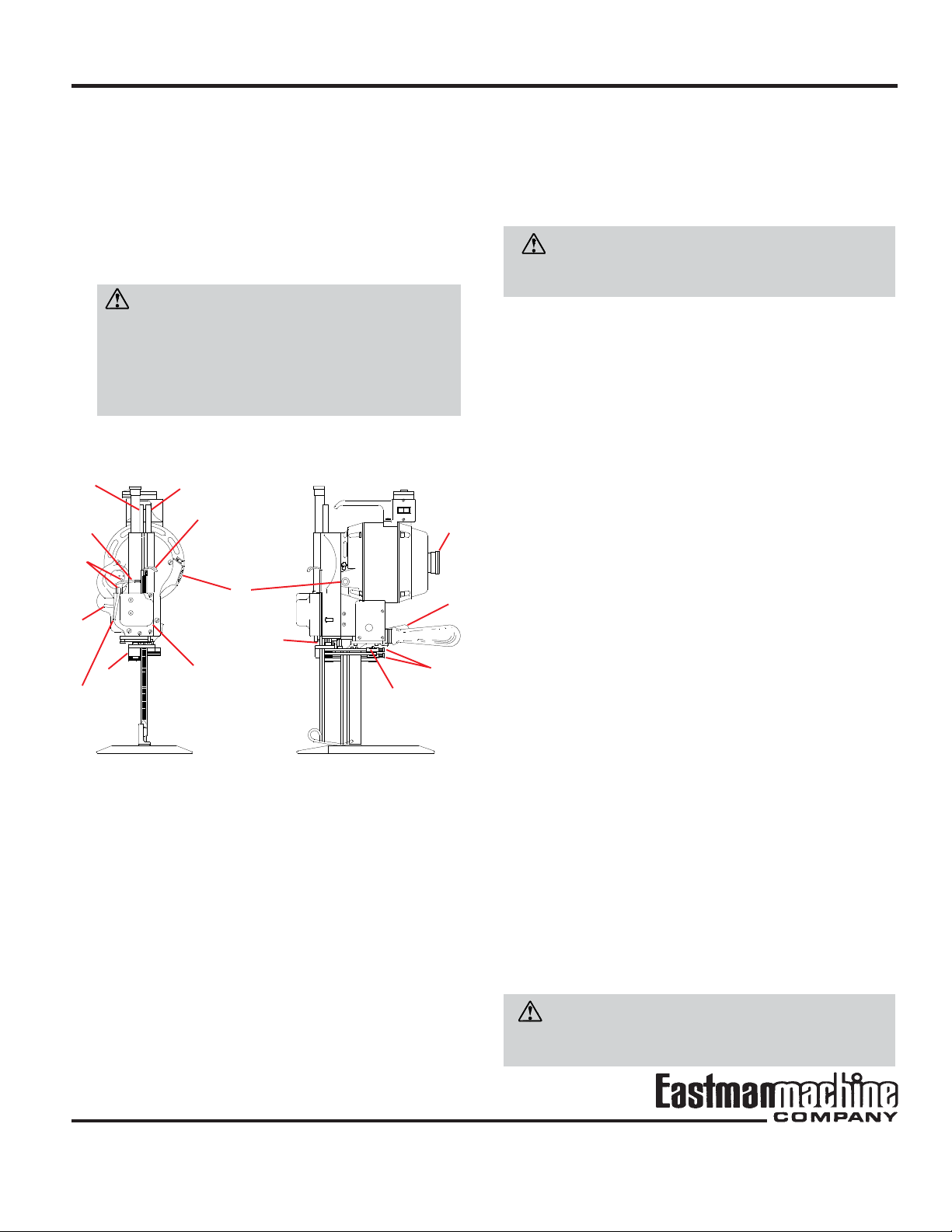
K
E
L
T
M
A
D
N
P
Q
H
S
O
A oil reservoir N pulley shaft
D release lever O belt pulley
E sharpener lever P plug
F turning knob Q cover
H bell crank release lever R pressure foot lever
K tube S sharpener bracket
L tube T knife guard/pressure foot
M oil lifting handle
Operating Procedure
Safety Considerations
WARNING
To prevent serious injury, read and follow these safety
precautions.
Before starting or using your machine:
1. Check that you know and understand the following:
• That proper voltage is supplied to machine.
• How to turn off the machine in an emergency.
• The meaning of all warning labels on the machine.
• What happens to the machine when you operate the
controls.
• Proper start-up procedures described in Initial Set
Up section.
F
R
• What to do in the event of a jam or other unforeseen
situation.
• How to disconnect power from the machine.
If you are not familiar with any of these points, ask your
supervisor or contact an Eastman representative.
2. Check the condition of your machine and working area.
Make sure that:
• There is no visible damage to the machine. Pay par-
ticular attention to the blade.
• No maintenance work is currently being performed
in your working area.
• No unnecessary people are in your working area.
• Your working area is clear of debris, spilled liquids,
food, drink, or other obstructions.
• Your clothing, hair, and jewelry cannot snag or be-
come tangled in the machine. Wear appropriate protective equipment as necessary. Remove all rings,
watches, neckties, and other loose objects. Tie up
hair or wear a hair net.
Figure 2. Controls and Adjustments
If you are uncertain about any of these points, do NOT use
the machine.
WARNING
Failure to use all recommended safety measures and
equipment may result in serious personal injury.
Form C-1572
3

EASTMAN
Starting the Machine
If you have had the machine less than one month or if it
has stood idle for any length of time, turn the motor on and
off a few times before running it continuously. This permits
the oil to warm up and flow easily into the close-fitting moving parts.
CAUTION
Failure to warm up your machine adequately may damage the motor.
Making a Cut
WARNING
Failure to keep hands, arms, and hair away from the knife
area at all times may result in serious personal injury.
1. Bring the machine up to the material spread.
2. Switch on the main power to activate the automatic
pressure foot lock.
3. Raise the knife guard/pressure foot by depressing the
pressure foot lever (Figure 2, R) and lifting the knife
guard/pressure foot lifting handle (Figure 2, T). Raise
the pressure foot only enough to clear the material
being cut.
Turning Off the Machine
When you have finished using your machine:
1. Position the power switch to off.
2. Make sure the knife guard/pressure foot is lowered to
the baseplate by depressing the pressure foot lever
(Figure 2, R).
3. Disconnect the attachment plug from the power source.
4. In cold weather, ensure that the machine is kept in a
warm place when not in use.
Routine Maintenance
WARNING
Always unplug the machine before performing maintenance, adjustments, or repairs.
WARNING
After servicing the machine, always make sure the plate
bolt nut is securely fastened (Figure 3, X on page 6)
before resuming cutting operation.
4. Press the start button. Allow the blade to reach full
speed, and enter the fabric.
5. Using the pressure foot lever (Figure 2, R) and the knife
guard/pressure foot lifting handle (Figure 2, T), lower
the pressure foot so that it is slightly above the material
being cut. This will prevent the material from reciprocating.
6. Begin cutting.
7. When you are not making a cut, or when the machine
is not in use, keep the knife guard/pressure foot lowered
to the baseplate by depressing the pressure foot lever
(Figure 2, R).
8. Turn off the machine when not cutting fabric.
Care of the Machine
To ensure proper operation of your machine, carry out the
following procedures at the intervals indicated. If you use
your machine intensively, consider performing these procedures more often.
Daily
Remove the knife and clean the knife slides with the slot
cleaner (Figure 7, 2 on page 9) included with machine. To
prevent undue accumulation of lint, do NOT oil the plate
rollers. If the rollers stick, remove them from the plate and
wash them in cleaning solvent.
Twice Weekly
Use an approved air hose or bellows to blow any lint from
around the motor and sharpener.
4
Form C-1572

WARNING
Failure to wear eye protection when using air hose or
bellows may result in serious eye or facial injuries.
Weekly
Remove the cover (Figure 2, Q) and clean any lint from
around the screw mechanism in the sharpener.
2. Remove the plug (Figure 2, P) and insert a grease tube.
Squeeze an amount of grease approximately the size
of a pea into the opening.
WARNING
Routinely check the tightness of the operating handle to
ensure a secure connection.
Lubrication
Lubricate your machine according to the following
schedule:
CAUTION
Use only specially compounded Eastman 30-weight,
non-detergent oil. Use of sewing machine oil or detergent oil may result in damage to your machine. Do not
oil the baseplate rollers. Use of an excessive amount of
oil may damage the machine.
Daily
1. Place two drops of oil at each of the two locations shown
in Figure 2, M. Use an oil can with a small spout. (A
suitable oil can is furnished with the machine.)
2. Fill the oil reservoir (Figure 2, A) for continuous use. If
you only use the machine intermittently, you can use
less oil.
Weekly
1. Carry out the Daily lubrication schedule above.
Sharpening the Knife
Sharpen the knife at frequent intervals or whenever you
feel it is not cutting adequately:
1. Take the machine out of the lay.
2. Drop the knife guard/pressure foot using the pressure
foot lever (Figure 2, R on page 3), located next to the
machine operating handle.
3. Press the sharpener lever (Figure 2, E) downward with
a slow, firm pressure to engage the sharpening mechanism. Too fast a lever action may cause the lever to
lock. If this occurs, lift the release lever (Figure 2, D)
and start over again.
Removing the Sharpener
1. Disconnect the machine from the power source.
2. Using the turning knob (Figure 2, F) raise the blade to
top position.
3. Press the sharpener lever (Figure 3, E on page 6)
approximately halfway down and to the neutral position,
and lower the sharpener by hand.
2. Apply one drop of oil only to each of the following:
• Tubes at locations shown as Figure 2, K and L.
• Pulley shaft shown as Figure 2, N.
• Belt pulley shown as Figure 2, O.
Monthly
1. Carry out the Daily and Weekly lubrication schedules
above.
WARNING
This machine is equipped with a very sharp knife. Remove the knife when working in this area. Failure to keep
hands, arms, and hair away from the knife area may result
in serious personal injury.
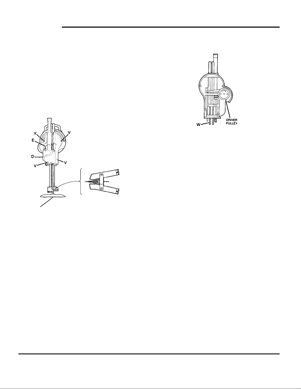
4. Remove the back guide (Figure 3).
Form C-1572
5
EASTMAN
5. Press the lever (Figure 3, E) to a neutral position and
raise the sharpener to the top (original) position.
6. Remove the four hold-down nuts (Figure 3, V), unplug
solenoid cord and remove the sharpener.
Note: If you press the sharpener lever (Figure 3, E)
down too far (beyond the neutral position), it will lock
the sharpener bracket. If this occurs, lift the release
lever (Figure 3, D) and start over again.
BACK GUIDE
W square shaft
Figure 4. Replacing the Rubber Driver Pulley
3. Hold the square shaft with a wrench. Position the
wrench as close as possible on the shaft to the sharp-
ener housing.
D release lever
X
Figure 3. Removing the Sharpener
E sharpener lever
V hold-down nut
X plate bolt nut
Replacing the Rubber Driver Pulley
The sharpener is driven by a rubber driver pulley, as shown
in Figure 4. Replace this driver pulley whenever it appears
to be worn or damaged, as follows:
1. Remove the sharpener from the machine (see Remov-
ing the Sharpener on page 5).
2. Press the sharpener lever (Figure 3, E) to a neutral
position and lower the sharpener until an inch of the
square shaft (Figure 4, W) is exposed.
4. Use a spanner wrench to remove the driver pulley
by turning it clockwise as indicated by the arrow in
Figure 4.
Note: The pulley has a left-hand thread.
5. Reassemble the new pulley on the sharpener.
6. Reassemble the sharpener on the machine.
6
Form C-1572
Adjusting the Belt Sharpener
Adjusting Stabilizers for Central Alignment
Note: You can obtain all the special tools you will require
for adjusting the sharpener by ordering tool kit #820C2.
T
S
O
U
O rear pulley T front pulley
S slide with pulley U sharpener shoe
Figure 5. Changing the Sharpener Belts
WARNING
Failure to unplug the attachment plug from the power
source before performing maintenance may result in serious personal injury.
1. Disengage the attachment plug, if you have not already
done this.
2. Depress the sharpener lever (Figure 2, E on page 3)
halfway and lower the belt carrier to the extreme bottom
position.
3. Loosen the screws (Figure 6, 1) and disengage the
back guide (Figure 6, 6) from contact with the standard.
4. Loosen the screws (Figure 6, 2) and disengage the
stabilizers (Figure 6, 4 and 5).
Changing Sharpener Belts
1. Push the slide with pulley (Figure 5, S) inward to relieve
tension, then remove the worn belt.
2. Place the new belt over the front pulley (Figure 5, T),
then between the sharpener shoe (Figure 5, U), and
then over the rear pulley (Figure 5, O).
3. Release the slide with pulley.
Note: Sharpener belts are available in four grits: Rough,
Coarse, Medium, and Fine. See Abrasive Belt Grits on
pages 17-18 for ordering information.
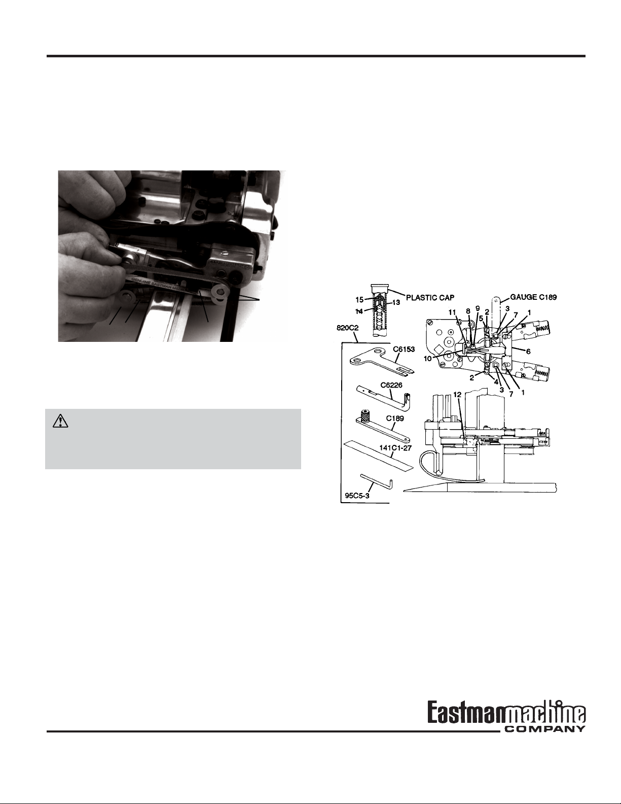
1 screw 9 locknut
2 screw 10 clamping arm
3 locknut 11 sharpener shoe
4 stabilizer 12 shoe
5 stabilizer 13 tube
6 back guide 14 spacer
7 pivot screw 15 locknut
8 stop screw
Figure 6. Adjusting the Stabilizers
Form C-1572
7

EASTMAN
5. Remove the locknut (Figure 6, 3).
6. Install gauge C189 on the exposed threaded end of the
pivot screw (Figure 6, 7) and press the end of the gauge
against the side of the standard.
7. Holding this position, engage the opposite stabilizer
(Figure 6, 4) firmly against the side of the standard and
tighten the screws (Figure 6, 2).
8. Remove tool C189 and press the positioned stabilizer
(Figure 6, 4) against the side of the standard. Then
fasten the opposite stabilizer (Figure 6, 5) firmly against
the standard.
9. Re-engage the back guide (Figure 6, 6) in loose contact
with the back of the standard.
Checking the Sharpener Shoes
The shoes should swing in and out freely without excessive up and down play. If adjustment is necessary, proceed as follows:
1. Loosen the locknuts (Figure 6, 3) and tighten the
screws (Figure 6, 7) as required.
Checking the Extreme Down Position of the Sharpener
The correct down position is with the tip of the knife at the
center of the belt on the shoe (Figure 6, 12). The belt should
be in the most downward position, and the knife should be
in the most upward position. If the belts are too high, the
bottom point of the knife will not sharpen. If the belts are
too low, the bottom point of the knife will round off excessively. If adjustment is necessary:
1. Raise the belt carrier to the up position.
2. Remove the plastic cap from the tube for the screw
shaft.
3. Insert a pin through the hole in the tube (Figure 6, 13)
to prevent the spacer (Figure 6, 14) from turning. Then
remove the locknut (Figure 6, 15).
The following step describes the correct procedure for
setting spacer adjustment on different stroke machines:
Note: Prior to beginning adjustment, be sure that the
spacer is threaded fully onto screw shaft.
Stroke Turns
2. Check the clamping arm (Figure 6, 10) with the belt
carrier in the most downward position and the knife in
the most upward position. The clamping arm should
keep the sharpener shoe from moving in. If it fails to do
so, the serrations on the clamping arm are worn or the
sharpener shoe (Figure 6, 11) is worn.
3. Replace worn part(s) as necessary.
1-1/8" 11
1-1/4" 9
1-1/2" 13
1-3/4" 8
Note: Each turn = 1/32"
4. Turn the spacer clockwise with wrench C6153 to raise
the bottom position, or turn counter-clockwise to lower
the position.
Note: One turn in either direction adjusts the position
by 1/32".
8
Form C-1572
 Loading...