

Eastman 555, 565, 623 User Manual
etSTMAN
OPERATION,
r
LUBRICATION
AND
CARE
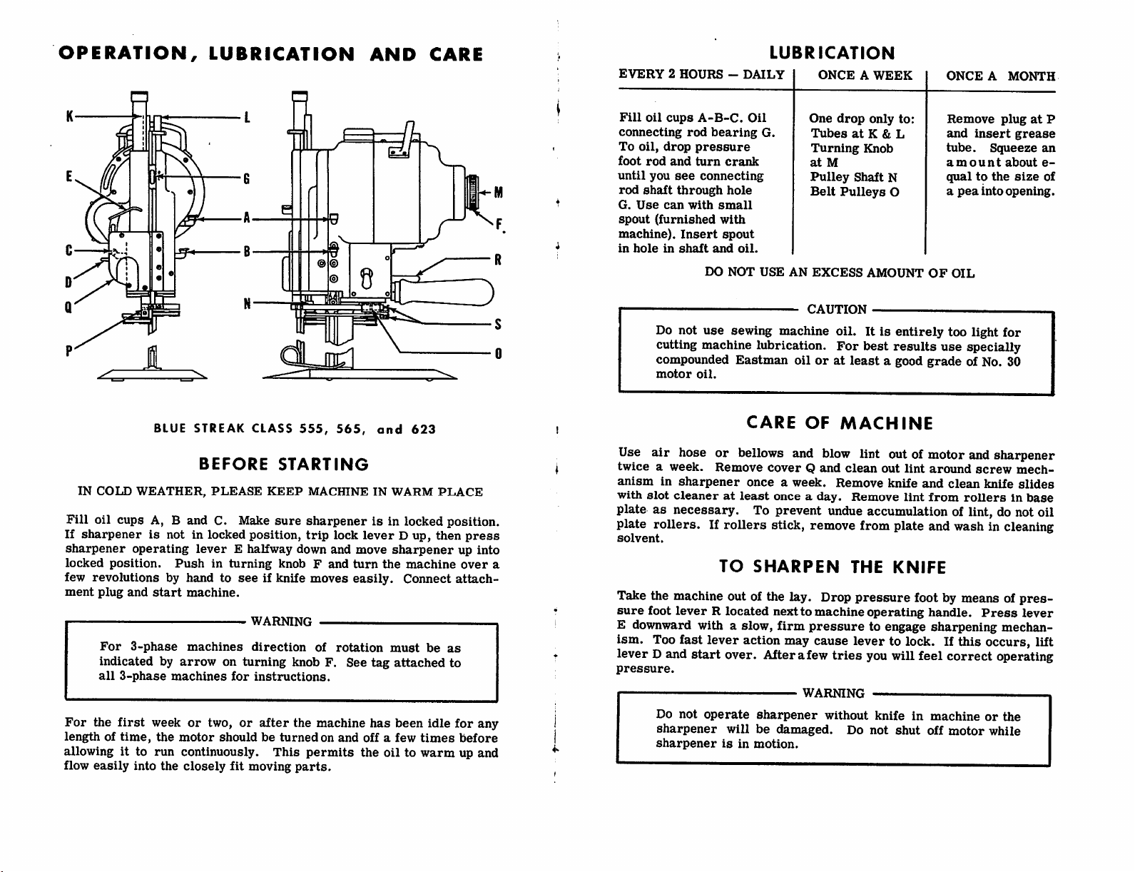
EVERY2HOURS-DAILY
Fill
oil
cups
connecting
To
oil,
foot
rod
until
you
rod
shaft
G.
Use
spout
(furnished
machine).
in
holeinshaft
Do not
drop
and
see
through
can
A-B-C.
rod
pressure
turn
connecting
with
Insert
DO
use
Oil
bearing
small
and
crank
hole
with
spout
NOT
G.
oil.
USE
sewing machine
cutting machine lubrication.
compounded
motor
Eastman
oil.
LUBRICATION
ONCEAWEEK
One
drop
Tubes
at
Turning
at
M
Pulley
Belt
AN
CAUTION
Shaft
Pulleys
EXCESS
oil.Itis
For
oilorat
least
only
to:
K & L
Knob
N
O
AMOUNT
entirely
best
results
a good
ONCE
Remove
and
insert
tube.
amount
qualtothe
a
pea
into
OF
OIL
too light
use specially
grade
of No. 30
A
MONTH
plugatP
grease
Squeeze
about
size
opening.
for
an
e-
of
BLUE
STREAK
IN
COLD
WEATHER,
Fill
oil cups A, B and C. Make
If
sharpenerisnot in locked
sharpener
locked
few
ment
operating
position.
revolutions
plug
and
For
3-phase
leverEhalfway
Pushinturning
by hand to
start
machine.
machines
indicatedbyarrow
all
3-phase
For
the
first
lengthoftime,
allowing it to
flow
easily
into
machines
week
or
the
motor
run
continuously.
the
closely
CLASS
BEFORE
PLEASE
555,
STARTING
KEEP
sure
position,
down
knobFand
see
if knife
WARNING
direction
on
turning
for
two,orafter
shouldbeturnedonand
knob F. See
instructions.
the machine
This
fit
moving
parts.
565,
and
623
MACHINEINWARM
PLACE
sharpenerisin locked position.
trip
lock
and
moves
of
rotation
permits
leverDup,
move
sharpener
turn
the
easily.
must
tag
has
offafew
the
oiltowarmupand
machine
Connect
be
attached
been
idle
times
then
as
to
press
up
into
over
attach
for
any
before
Use
air
hose
twiceaweek.
anism
with
in
sharpener
slot
cleaneratleast
CARE
or
bellows and blow lint out of motor and sharpener
Remove
onceaweek.
OF
MACHINE
coverQand
clean
Remove
once a day. Remove
out
knife
lint
lint
around
and
from
clean
screw
mech
knife
slides
rollersinbase
plate as necessary. To prevent undue accumulation of lint, do not oil
plate rollers. If
solvent.
a
rollers
TO
Take the machine out of the lay. Drop
sure
foot
leverRlocated
E downward with a slow,
ism. Too fast
lever D and
pressure.
Do
sharpener
sharpener
not
lever
start
over. After a few
operate
willbedamaged.
isinmotion.
stick, remove from plate and wash in cleaning
SHARPEN
nextto
firm
action may cause
WARNING
sharpener
THE
KNIFE
pressure
machine
operating
pressuretoeng^e
lever
to lock. If
tries
you will feel
without
knifeinmachineorthe
Do
not
shut
foot by means of
handle.
Press
sharpening mechan
this
correct
off
motor
pres
lever
occurs, lift
operating
while
fwr
— \
>
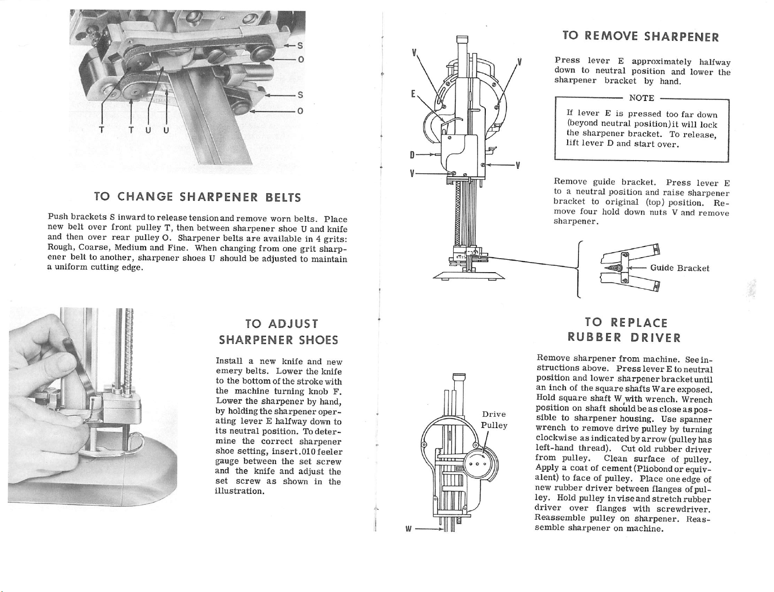
TO
REMOVE
SHARPENER
TO
CHANGE
Push
brackets
S inward to
new belt over front pulley T, then between
and then over
Rough,
ener
a
Coarse, Medium and Fine. When changing from one
belt to another, sharpener shoes U should be adjusted to maintain
uniform
cutting
rear
pulley O. Sharpener belts
edge.
SHARPENER
release
tensionand remove worn
BELTS
sharpener
are
available in 4 grits:
TO
shoe U and knife
ADJUST
SHARPENER
belts.
grit
SHOES
Place
sharp
Press
down to
sharpener
lever E approximately halfway
If
leverEis
(beyond
neutral
neutral position)it will lock
bracket
position
by hand.
NOTE
pressed
and
too
far
the sharpener bracket. To release,
lift
leverDand
Remove
to a
neutral
bracket
move
four
sharpener.
RUBBER
TO
guide
to
hold
original
start
bracket.
position
and
(top)
down
REPLACE
DRIVER
over.
Press
raise
position.
nutsVand
Guide
Bracket
lower
the
down
lever
sharpener
Re
remove
E
Install
emery
to
the
Lower
by
ating
its
mine
shoe
gauge
and
set
illustration.
a
new
belts.
the
bottomofthe
machine
the
sharpener
holding
neutral
the
leverEhalfway
position.
the
correct
setting,
between
the
knife
screw
as
knife
Lower
stroke
turning
sharpener
insert
the
and
shown
and
the
knife
with
knob
by hand,
oper
down
To
deter
sharpener
.010
feeler
set
screw
adjust
in
new
F.
to
the
the
Drive
Pulley
Remove
structions
position
an inch of the squareshafts W
Hold
sharpener
and
square
above.
lower
shaft
from
machine.
Press
leverEto
sharpenerbracketuntil
Wwth
wrench.
are
See
neutral
ejqjosed.
Wrench
in
position on shaft should beas closeaspos
sible to
wrench to remove
sharpener
housing. Use spanner
drive
pulley by turning
clockwise as indicated byarrow(pulleyhas
left-hand
thread).
Cut
old
rubber
driver
from pulley. Clean surface of pulley.
Apply
a coat of cement (Pliobondor equiv
alent) to face of pulley. Place oneedgeof
new rubber
ley.
driver
Reassemble
semble
Hold
pulleyinvise
over
sharpener
driver
flanges
pulley on
between flanges ofpul
and
on
machine.
stretch
with
sharpener.
inibber
screwdriver.
Reas
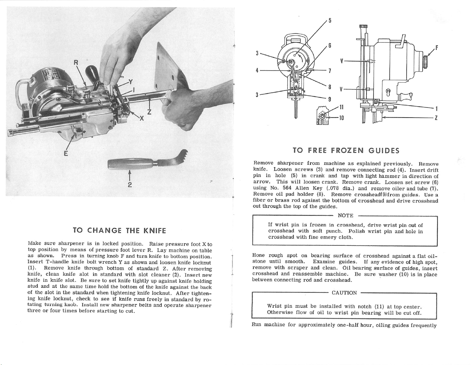
TO
FREE
FROZEN
GUIDES
TO
Make
sure
sharpener
top position by
as shown.
Insert
(1).
knife,
T-handle
Remove
clean
meansofpressure
Press
in
knife
knife through bottom of standard Z. After removing
knife
slotinstandard
knife in knife slot. Be
stud
and at
of the
slot
the
in the
same
standard
CHANGE
is
in locked position.
turning
bolt
knob F and
wrenchYas
suretoset
time
hold the bottom of the knife
when tightening knife locknut. After tighten
THE
foot
with
lever
turn
shown
slot
KNIFE
Raise
R. Lay
knife to
and
cleaner
pressure
machineontable
bottom
loosen
knife
(2).
Insert
foot X to
position.
locknut
new
knife tightly up against knife holding
against
the
back
ing knife locknut, check to see if knife runs freely in standard by ro
tating turning knob. Install new
threeorfour
times
before
sharpener
startingtocut.
belts
and
operate
sharpener
Remove
knife.
pin
arrow.
using
Remove
fiberorbrass
out
——
Hone
Loosen
in
hole
No. 564
through
If
wrist
crosshead
crosshead
rough
sharpener
This
oil
pad
the
spot
from
machineasexplained previously. Remove
screws
(5) in
will
Allen
holder
rod
topofthe
pinisfrozenincrosshead,
with
with
(3)
and
crank
loosen
crank.
Key (.078 dia.)
(8).
against
on
guides.
soft
fine
bearing
the
punch.
emery
remove
and
tap
with
Remove
connecting
light
crank.
and
Remove
bottomofcrosshead
surface
crosshead(9)from
NOTE
cloth.
———
Polish
of
drive
wrist
crosshead
rod
(4).
hammerindirection
Loosen
remove
and
wrist
pin
set
oiler
and tube (7).
guides.
drive
pin
out of
and
hole
againstaflat
Insert
screw
Use a
crosshead
in
drift
oil
stone until smooth. Examine guides. If any evidence of high spot,
remove
crosshead
between
with
and
connecting
Wrist
pin
Otherwise
scraper
reassemble
rod
^
must
flow of
and
clean.
machine. Be
and
crosshead.
be
installed
oiltowrist
Oil
bearing
sure
CAUTION
with notch (11)attop
pin
bearing
surfaceofguides,
washer
(10) is in place
center.
willbecut
off.
insert
Run machine for approximately one-half hour, oiling guides frequently
of
(6)
1
I
list
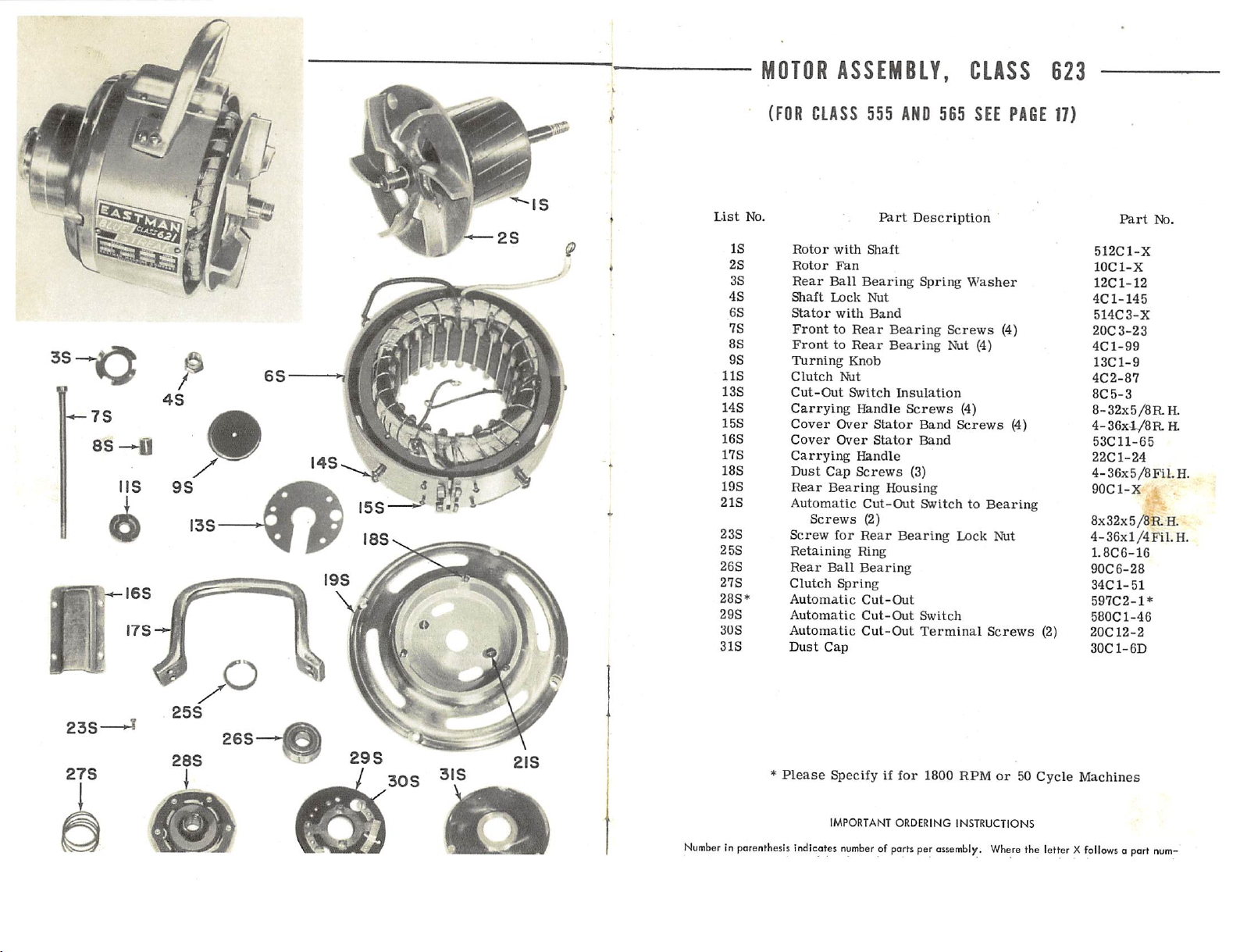
MOTOR
(FOR
No.
ASSEMBLY,
CLASS
555
Part
AND
565
Description
CLASS
SEE
PAGE
623
17)
Part
No.
8s—n
2S
3S
4S
6S
7S
8S
OS
118
13S
148
15S
16S
17S
18S
19S
2
IS
23S
25S
26S
27S
28S*
29S
30S
31S
IS
Rotor
with
Rotor
Fan
Rear
Ball
Bearing
Shaft
Lock
Stater
with
FronttoRear
FronttoRear
Turning
Clutch
Cut-Out
Carrying
Cover
Cover
Carryii^
Dust
Rear
Automatic
Knob
Nut
Switch
Ifendle
Over
Over
Handle
Cap
Screws
Bearing
Cut-Out
Screws
Screw
for
Rear
Retaining
Rear
Clutch
Automatic
Automatic
Automatic
Dust
Ball
Cap
Ring
Bearing
Spring
Cut-Out
Cut-Out
Cut-Out
Shaft
Nut
Band
Stator
Stator
(2)
Sprii^
Bearing
Bearing
Insulation
Screws
Nut (4)
Screws
Band
Band
(3)
Housing
SwitchtoBearing
Bearing
Switch
Terminal
Washer
(4)
Screws
Lock
Screws
Nut
(4)
(4)
(2)
512C1-X
lOCl-X
12C1-12
4C1-145
514C3-X
20C3-23
4C1-99
13C1-9
4C2-87
8C5-3
8-32x5/8RH.
4-36X-L/8RH,
53C11-65
22C1-24
4-36x5/8
90C1-X
FiLH.
;
8x32x5/8Ra
4-36xl/4Fil.H.
1.8C6-16
90C6-28
34C1-51
597C2-1*
580C1-46
20C12-2
30C1-6D
*
Please
NumberInparenthesis
indicotes
Specify If
IMPORTANT
numberofports
for
1800
ORDERING
per
ossembly.
RPMor50
INSTRUCTIONS
Where
Cycle
Machines
the
letterXfollowsaport
num-
 Loading...