

Page 1

Instruction Manual for
Thank you for your purchase! This instruction manual will guide you through the installation and operation of your Spektrum™ and JR™
Data Interface (the Interface). Please read the entire manual carefully before proceeding. If, after you read the manual, you have further
questions or problems, see the Support page on http://www.eagletreesystems.com for additional information, or email us at
support@eagletreesystems.com.
IMPORTANT: It is extremely unlikely that the installation of the Interface will affect your model’s radio range or control. But, as always
after making an electronics change to your model, it is very important that you range and function test your model once the Sensor is
installed to ensure that there is no impact on your system. Make sure that your “antenna down” operating range is within the
manufacturer’s specifications. See your Radio owner’s manual for the correct procedure for your equipment. DO NOT OPERATE IF
YOUR MODEL DOESN’T PASS THE ANTENNA DOWN RANGE CHECK.
IMPORTANT: Before connecting the Spektrum interface cable to your Spektrum Receiver, ensure that you have configured your
eLogger or Recorder for the Spektrum interface, as described in the “Configuring the Interface with the Windows Application”
section below!
Packing List
Your package should include the following: The Interface cable, and a printed version of this manual. Please check our support web page
for the electronic version of this manual which may be updated if changes were made after printing.
What the Interface Does
For the first time ever, see and hear how your receiver is performing real time, while you fly! The interface provides support for wireless
telemetry and logging of all the Spektrum™ and JR ™ RF link performance parameters, with “FlightLog” compatible RX’s. Just think,
while you do your range check, get instant feedback on the Seagull LCD display about how your RF link is performing. And best of all,
audible ‘beep’ alarms can be programmed on the Wireless Dashboard display, to alert you in real time when things start to go wrong during
flight! With the programmable beep capability, you keep your eyes on your model, where they should be, knowing that your Receiver is
getting a good signal at all times unless alarms sound. Fly with confidence knowing that your radio link is performing optimally!
The Interface gives you access to the following parameters:
• Receiver Holds – displays a count of the number of Failsafe Holds that have occurred
• Receiver Lost Frames – displays how many frames have been missed during your flight
• Receiver Antenna A, B, Left and Right Fades – displays fade (poor signal) counts of each antenna (up to four). This helps you to
determine which of your antennas needs to be repositioned.
NOTE: at this time, the Interface cable CANNOT be used simultaneously with the GPS Expander, as they use the same port. Eagle Tree is
developing a solution to this shortcoming.
Supported Products
The Interface cable is designed to plug directly into the Data port of most “FlightLog” compatible Spektrum™ and JR™ receivers. It will
not work with any other receiver brand or model! NOTE: Eagle Tree has received a report that Spektrum™ and JR™
PowerSafe™ receivers will start up in bind mode when connected to our Recorders during power-up, so PowerSafe™ receivers may
not be compatible.
The Interface works with the eLogger V4 or V3 (not the eLogger V1 or V2), with all versions of our Pro, Glide, Flight, Car and Boat Seagull
and Recorder products that have shipped since 2007, and have a firmware version of 4.XX or higher. If you have a “3.xx” or lower recorder
firmware version, a hardware upgrade is required. Please see our support web page for more information on hardware upgrades.
Steps to Follow
Installation and use of the Interface should be quite easy and enjoyable if you follow these few steps:
• Read through the manual to understand the warnings, determine the installation and setup sequence, etc.
• Upgrade the Windows Application and Firmware for your Recorder as described in the “Windows Application and Firmware
Update” section below.
• Install and configure the Interface as described below.
Spektrum™ and JR™ Data Interface
Document Version 1.5
Copyright © 2007, 2008 Eagle Tree Systems, LLC
http://www.eagletreesystems.com
Page 2
Page
2
Windows Application and Firmware Update
To use the Interface, you must update to Eagle Tree Windows Application version 6.08 or higher. To update, download the latest
application from the support page of our website, located at http://eagletreesystems.com/Support/apps.htm . After downloading and
installing the Application, the firmware of your eLogger or Recorder and Dashboard will need to be updated. To upgrade your firmware,
just choose “Tools, Firmware Control” and click the Update button.
Connecting the Interface Cable to your Receiver
The 3 pin JR style plug on the interface cable is polarized. Simply plug the JR end of the cable into the Data port of your Receiver. NOTE:
there are only two wires on the JR end of the cable, and the color of these two wires is probably different than the “standard” wire colors.
Just plug the Interface cable in based on the polarization of the JR plug. NOTE: with a standard servo Y cable, you can connect your
Spektrum™ Flight Log™ LCD data display at the same time as the Eagle Tree Interface cable.
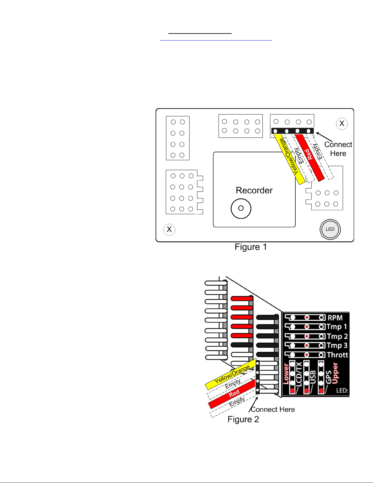
Connecting the Interface to your Data
Recorder (NOT eLogger V3)
The 4 pin plug of the Interface cable plugs into the
“GPS” port of your Data Recorder, as shown in Figure
1. Note the correct polarity of the Interface cable
plug, as shown in Figure 1. NOTE: the Data
Recorder must be powered with less than about
5.5V for the Spektrum interface to operate
correctly!
Connecting the Interface to the eLogger V3
The 4 pin plug of the Interface cable plugs into the
“GPS” port of your eLogger V3, as shown in Figure 2.
Note the correct polarity of the Interface cable plug, as
shown in Figure 2.
Configuring the Interface with the Windows
Application
If you have not already done so, set up the Recorder
software as described in your instruction manual.
Then, click connect your Recorder or eLogger V3 to the PC with the USB cable, and choose “Tools, Enable Spektrum™ Flight Log
Interface.” Then, click the “Enable Spektrum™ Interface” checkbox, and click OK.
Logging Interface Data
To log interface data, just click “Tools, Choose Parameters to Log in the
Recorder” and check the “Spektrum™ AR9000™ Flight Log Interface”
checkbox.
Displaying Interface Data the Windows Application
Once the Interface is enabled in software as described above, whenever
data are downloaded from the recorder and played back, or when PC Live
Mode is started, Interface data will be displayed at the bottom of the
Windows Application screen. The format of the interface data is as
follows:
Spektrum: Holds=0, Lost Frames=0, Ant Fade A=0,
Ant Fade B=0, Ant Fade Left=0, Ant Fade Right=***
Note that when “***” is displayed for a particular antenna, this indicates
that the antenna is either not attached or not functioning properly.
Graphing Interface Data
To graph logged Interface data, click “Graph Data/2D Chart,” select either
the Left Y Axis or Right Y Axis, and select one or more of the Spektrum™
parameters for graphing.
Displaying Interface Data on the Seagull Dashboard
Copyright © 2007, 2008 Eagle Tree Systems, LLC
http://www.eagletreesystems.com
Page 3

Page
3
To configure the Interface to display Receiver performance parameters on your Seagull Wireless Dashboard, select “Tools, Choose
Parameters to Display on Seagull Wireless Dashboard LCD” and just choose the Spektrum™ parameter(s) you wish to display. See your
Seagull manual for more information on configuring Seagull parameters.
Note that in addition to being able to program an audible “High Alarm” with each of the Spektrum™ parameters and specifying how many
errors triggers the alarm, you can also check the “Reset the alarm count every one minute” option. With this option, the error count for that
parameter is reset every minute. If you are flying for a long time, or in an environment with lots of RF noise, this may be desirable to keep
the alarm from going off unless you get a lot of receiver errors in a short time.
Troubleshooting
Below is a list of problems that may be encountered, and steps to remedy them. If your particular issue is not addressed by the below, see
the Support page on http://eagletreesystems.com or email support@eagletreesystems.com. Include a full description of your problem, your
machine configuration, brands/models of receivers, transmitters and servos, Windows Application and Recorder firmware version if possible,
and any other relevant details.
Issue: I do not see the Spektrum™ interface options displayed in the software.
Solutions:
• Ensure that you have updated the Windows application to version 6.06 or greater, as described above, and that you have updated your
firmware.
• Make sure you have enabled the Spektrum™ interface as described in the software configuration section above.
Issue: AR9000™ Data is not being recorded.
Solutions:
• Ensure that you have selected logging of AR9000™ parameters as described in “Logging Interface Data” above.
• Ensure that the Interface cable is correctly connected between the Recorder/eLogger and the Data port of your receiver.
Issue: AR9000™ Data is not being displayed correctly on the Seagull Dashboard.
Solutions:
• Ensure that you have enabled Seagull display of Spektrum™ parameters as described in “Displaying Interface Data on the Seagull
Dashboard” above.
• Ensure that the Interface cable is correctly connected between the Recorder/eLogger and the Data port of your receiver.
Issue: The Spektrum™ interface does not appear to be working with my Data Recorder (not eLogger V3)
Solution:
• Ensure that are powering the Data Recorder with a power source less than about 5.5V
Spektrum and Flight Log are trademarks of Horizon Hobby, Inc. JR is a trademark of JR, Inc.
Limited Warranty
Eagle Tree Systems, LLC, warrants the Interface cable to be free from defects in materials and workmanship for a period of one (1) year from the date of
original purchase. This warranty is nontransferable. If your unit requires warranty service during this period, we will replace or repair it at our option.
Shipping cost to us is your responsibility. To obtain warranty service, email support@eagletreesystems.com for further instructions.
This limited warranty does not cover:
• The Software. See the Software license agreement for more information on Software restrictions.
• Problems that result from:
o External causes such as accident, abuse, misuse, or problems with electrical power
o Servicing not authorized by us
o Usage that is not in accordance with product instructions
o Failure to follow the product instructions
THIS WARRANTY GIVES YOU SPECIFIC LEGAL RIGHTS, AND YOU MAY ALSO HAVE OTHER RIGHTS WHICH VARY FROM STATE TO
STATE (OR JURISDICTION TO JURISDICTION). OUR RESPONSIBILITY FOR MALFUNCITONS AND DEFECTS IN HARDWARE IS LIMITED
TO REPAIR AND REPLACEMENT AS SET FORTH IN THIS WARRANTY STATEMENT. ALL EXPRESS AND IMPLIED WARRANTIES FOR
THE PRODUCT, INCLUDING, BUT NOT LIMITED TO, ANY IMPLIED WARRANTIES AND CONDITIONS OF MERCHANTABILITY AND
FITNESS FOR A PARTICULAR PURPOSE, ARE LIMITED IN TIME TO THE TERM OF THE LIMITED WARRANTY PERIOD AS DESCRIBED
ABOVE. NO WARRANTIES, WHETHER EXPRESS OR IMPLIED, WILL APPLY AFTER THE LIMITED WARRANTY PERIOD HAS EXPIRED.
SOME STATES DO NOT ALLOW LIMITATIONS ON HOW LONG AN IMPLIED WARRANTY LASTS, SO THIS LIMITATION MAY NOT APPLY
TO YOU.
WE DO NOT ACCEPT LIABILITY BEYOND THE REMEDIES PROVIDED FOR IN THIS LIMITED WARRANTY OR FOR CONSEQUENTIAL OR
INCIDENTAL DAMAGES, INCLUDING, WITHOUT LIMITATION, ANY LIABILTY FOR THIRD-PARTY CLAIMS AGAINST YOU FOR
DAMAGES, FOR PRODUCTS NOT BEING AVAILABLE FOR USE, OR FOR LOST DATA OR LOST SOFTWARE. OUR LIABILITY WILL BE NO
Copyright © 2007, 2008 Eagle Tree Systems, LLC
http://www.eagletreesystems.com
Page 4

Page
4
MORE THAN THE AMOUNT YOU PAID FOR THE PRODUCT THAT IS THE SUBJECT OF A CLAIM. THIS IS THE MAXIMUM AMOUNT FOR
WHICH WE ARE RESPONSIBLE. SOME STATES DO NOT ALLOW THE EXCLUSION OR LIMITATION OF INCIDENTAL OR
CONSEQUENTIAL DAMAGES, SO THE ABOVE LIMITATION OR EXCLUSION MAY NOT APPLY TO YOU
.
Copyright © 2007, 2008 Eagle Tree Systems, LLC
http://www.eagletreesystems.com
 Loading...