

Page 1
Instruction Manual for Servo Current Monitor MicroSensor
Thank you for your purchase! This instruction manual will guide you through the installation and operation of your Servo Current MicroSensor (the
Sensor). Please read the entire manual carefully before proceeding. If, after you read the manual, you have further questions or problems, see the
Support page on http://www.eagletreesystems.com for additional information, or email us at support@eagletreesystems.com.
IMPORTANT (READ FIRST!):
1) Please note that only one servo current sensor can be used with our eLogger or Data recorder products. It is not possible to connect more than one of
these sensors with these products.
2) Please note that when using the sensor with our Data Recorders, that the plug polarity is reversed (the red wire goes to the left, rather than to the right).
This is shown in Figure 2.
3) It is extremely unlikely that the installation of the Sensor will affect your model’s radio range or control. But, as always after making an electronics
change to your model, it is very important that you range and function test your model once the Sensor is installed to ensure that there is no impact on
your system. Make sure that your “antenna down” operating range is within the manufacturer’s specifications. See your Radio owner’s manual for
the correct procedure for your equipment. DO NOT OPERATE IF YOUR MODEL DOESN’T PASS THE ANTENNA DOWN RANGE
CHECK.
Packing List
Your package should include the following: The Sensor with universal servo connectors, and a printed version of this manual. Please check our support
web page for the electronic version of this manual which may be updated if changes were made after printing.
What the Sensor Does
The Sensor is a precision Ammeter, with 0.01A resolution. It is capable of recording up to +/-10A burst
current, but no more than +/-5A continuous current. It connects to your eLogger, Seagull, or Data Recorder
product to provide current/amperage measurement of Servos, or other low amperage devices. Servo Current
can be displayed and analyzed in 3 ways: 1) The live current and maximum current are displayed on the
PowerPanel LCD or Seagull Dashboard Display. This is very useful for quickly seeing how much current
your servo(s) are drawing without using a PC. 2) Servo Current is logged in the Recorder, for download to
your PC. 3) Servo Current is displayed and graphed (charted) with the Eagle Tree Windows application, or a
spreadsheet program.
Supported Uses and Products
The Sensor is intended to be used exclusively for recreational purposes in model planes, boats and cars. Any
other use is not supported. The Sensor works with all versions of the eLogger product, with all versions of
our “Pro” and “Glide” systems, and with flash upgradeable firmware versions of our Seagull Flight, Car and Boat (and Recorder) products (units with
firmware version “4.xx”). If you have a “3.xx” or lower recorder firmware version, a hardware upgrade is required. Please see our support web page for
more information on hardware upgrades.
Windows Application and Firmware Update
To use the Sensor, you must update to Eagle Tree Windows Application version 5.50 or higher. To update, download the latest application from the
support page of our website, located at http://eagletreesystems.com/Support/apps.htm . After downloading and installing the Application, the firmware of
your eLogger or Recorder and Dashboard will need to be updated. Version 4.91 or greater eLogger/Recorder firmware is required for the Sensor to
work correctly. Version 4.50 or greater Seagull Dashboard firmware is required if you are using the Sensor with the Wireless Dashboard. To upgrade
your firmware, just choose “Tools, Firmware Control” and click the Update button.
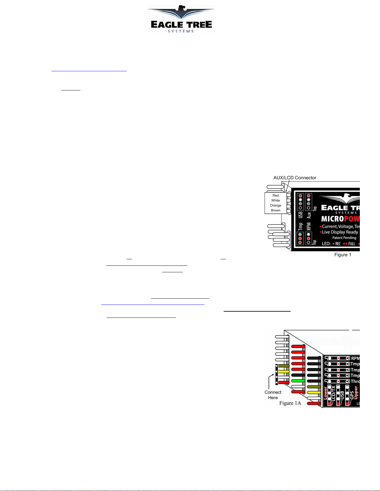
Connecting the MicroSensor to the eLogger V3
The MicroSensor plugs into the “LCD/TX” port of your eLogger V3, as shown in Figure 1A. If you have a
PowerPanel or other MicroSensors, those can “daisy chain” connect to the pins on the other side of your
MicroSensor, with the polarity as indicated on the MicroSensor label.
Connecting the Sensor to the eLogger V1/V2
The Sensor plugs into the “Aux” or “LCD” port of your eLogger V1/V2, as shown in Figure 1. If you have
a PowerPanel or other MicroSensors, those can “daisy chain” connect to the pins on the other side of your
Sensor, with the polarity as indicated on the Sensor label.
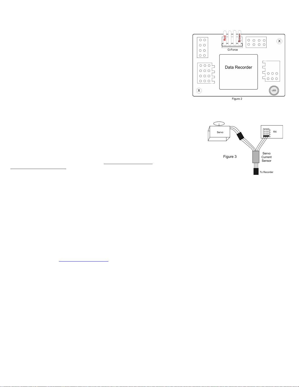
Connecting the Sensor to the Data Recorder
The 4 wire connector attached to the Sensor plugs into either the G-Force or EGT (“Thermo”) port of your
Data Recorder as shown in Figure 2. Make sure that you connect it in the correct location on the recorder, and with the correct polarity! NOTE: The
Servo Current Sensor is connected with the red wire on the left, which is backwards from the normal G-Force, EGT and transmitter connections.
Also, if you are already using both EGT and G-Force expanders, one of those can “daisy chain” to the Sensor as described in the section above.
Configuring the Sensor with the Windows Application
If you have not already done so, set up the Recorder software as described in your instruction manual. Then, choose one or more of the Sensor options
below:
Document Version 1.3
Copyright © 2007 Eagle Tree Systems, LLC
http://www.eagletreesystems.com
Page 2
Page
2
Logging Servo Current
To log servo current, just click “Tools, Choose Parameters to Log in the Recorder” and check the
“Servo Current” box.
Displaying Servo Current in the Windows Application
To display the Servo Current Gauge and/or Numeric Servo Current Display, click “Tools, Choose
Instruments to Display on the PC Screen” and check the “Servo Current Ammeter,” and/or
“Numeric Servo Current Amps” boxes.
Graphing Servo Current
To graph altitude, click “Graph Data/2D Chart,” select either the Left Y Axis or Right Y Axis, and
select “Servo Current” for graphing.
Displaying Servo Current on the PowerPanel or Seagull Dashboard
Select “Tools, Configure PowerPanel Display” or “Tools, Choose Parameters to Display on Seagull
Wireless Dashboard LCD” and choose “Servo Current” for display.
Installing the Sensor in your Model, with your Servos
IMPORTANT: The servo wires attached to the sensor are not designed to carry more than 5 amps continuous current (10 amps brief surge).
Ensure that your setup will not draw more than this, and make sure to test the setup on the bench
before flying to make sure the sensor wires do not overheat! To measure the current draw of a single
servo, simply connect the Sensor as shown in Figure 3, using the attached universal servo connectors. To
measure the current draw of all your servos and your receiver at the same time, simply connect the sensor
between your BEC/RX Battery and your receiver (note the amperage limitation above!).
Troubleshooting
Below is a list of problems that may be encountered, and steps to remedy them. If your particular issue is
not addressed by the below, see the Support page on http://eagletreesystems.com or email
support@eagletreesystems.com. Include a full description of your problem, your machine configuration,
brands/models of receivers, transmitters and servos, Windows Application and Recorder firmware version if
possible, and any other relevant details.
Issue: Servo Current always reads zero on my display, and/or in my recordings
Solutions:
• Ensure that the Sensor is connected correctly to the or Recorder
• Ensure that you have updated the recorder firmware to 4.91 or later.
• If you are downloading data and seeing zero current, ensure that you are logging Servo Current, under “Tools, Choose Parameters to Log in the
Recorder”
Specifications
Range: approximately +/- 5A Continuous, up to 10A surge
Resolution: approximately 0.01A
Limited Warranty
Eagle Tree Systems, LLC, warrants the Sensor to be free from defects in materials and workmanship for a period of one (1) year from the date of original purchase. This
warranty is nontransferable. If your unit requires warranty service during this period, we will replace or repair it at our option. Shipping cost to us is your responsibility. To
obtain warranty service, email support@eagletreesystems.com for further instructions.
This limited warranty does not cover:
• The Software. See the Software license agreement for more information on Software restrictions.
• Problems that result from:
THIS WARRANTY GIVES YOU SPECIFIC LEGAL RIGHTS, AND YOU MAY ALSO HAVE OTHER RIGHTS WHICH VARY FROM STATE TO STATE (OR
JURISDICTION TO JURISDICTION). OUR RESPONSIBILITY FOR MALFUNCITONS AND DEFECTS IN HARDWARE IS LIMITED TO REPAIR AND
REPLACEMENT AS SET FORTH IN THIS WARRANTY STATEMENT. ALL EXPRESS AND IMPLIED WARRANTIES FOR THE PRODUCT, INCLUDING, BUT
NOT LIMITED TO, ANY IMPLIED WARRANTIES AND CONDITIONS OF MERCHANTABILITY AND FITNESS FOR A PARTICULAR PURPOSE, ARE LIMITED
IN TIME TO THE TERM OF THE LIMITED WARRANTY PERIOD AS DESCRIBED ABOVE. NO WARRANTIES, WHETHER EXPRESS OR IMPLIED, WILL APPLY
AFTER THE LIMITED WARRANTY PERIOD HAS EXPIRED. SOME STATES DO NOT ALLOW LIMITATIONS ON HOW LONG AN IMPLIED WARRANTY
LASTS, SO THIS LIMITATION MAY NOT APPLY TO YOU.
WE DO NOT ACCEPT LIABILITY BEYOND THE REMEDIES PROVIDED FOR IN THIS LIMITED WARRANTY OR FOR CONSEQUENTIAL OR INCIDENTAL
DAMAGES, INCLUDING, WITHOUT LIMITATION, ANY LIABILTY FOR THIRD-PARTY CLAIMS AGAINST YOU FOR DAMAGES, FOR PRODUCTS NOT
BEING AVAILABLE FOR USE, OR FOR LOST DATA OR LOST SOFTWARE. OUR LIABILITY WILL BE NO MORE THAN THE AMOUNT YOU PAID FOR THE
PRODUCT THAT IS THE SUBJECT OF A CLAIM. THIS IS THE MAXIMUM AMOUNT FOR WHICH WE ARE RESPONSIBLE. SOME STATES DO NOT ALLOW
THE EXCLUSION OR LIMITATION OF INCIDENTAL OR CONSEQUENTIAL DAMAGES, SO THE ABOVE LIMITATION OR EXCLUSION MAY NOT APPLY TO
YOU
o External causes such as accident, abuse, misuse, or problems with electrical power
o Servicing not authorized by us
o Usage that is not in accordance with product instructions
o Failure to follow the product instructions
.
Copyright © 2007 Eagle Tree Systems, LLC
http://www.eagletreesystems.com
 Loading...