

Page 1
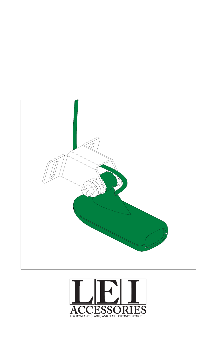
INSTALLATION INSTRUCTIONS MANUAL
MODELS
HS-WS, HS-WSPC,
AND HS-WSBK
TRANSDUCERSTRANSDUCERS
TRANSDUCERS
TRANSDUCERSTRANSDUCERS
Page 2

TOOLS YOU WILL NEED:
TRANSOM MOUNT:
3/8" DRILL with a variety of small bits
Two (2) #12 stainless steel screws (to attach bracket to the transom.)
Marine grade caulking compound (to seal screws)
SHOOT-THRU-HULL MOUNT:
100 grit sandpaper
One package of the either of the following epoxies:
Power Poxy®, 1 oz package. Made by: Power Poxy® Adhesives, Inc.
or
True Value® brand TRUE BOND epoxy or PLASTIC WELDER
sold by True Value® stores.
or
Devcon® brand PLASTIC WELDER
TM
epoxy.
TM
epoxy
Copyright © 1995 Lowrance Electronics, Inc. All rights reserved.
Features and specifications subject to change without notice.
Page 3

The HS-WS is a transom mount transducer with a gray connector. It can
be installed on any outboard or stern-drive (inboard\outboard) powered
boat. It can also be permanently installed inside the boat to "shootthrough" the hull on some fiberglass boats. The HS-WSPC is the same
as the HS-WS, however it has a power cable attached for sonar units
that have only one connector for both the power and transducer. If you
are installing a HS-WSPC transducer, install the transducer before wiring the power cable. See the power cable instructions in the back of this
manual for more information. The HS-WSBK is the same as a HS-WS,
but the connector is different.
The “kick-up” mounting bracket helps prevent damage if the transducer
strikes an object while the boat is moving. If the transducer does “kickup”, the bracket can easily be pushed back in place without tools.
Read this manual carefully before attempting the installation. Determine
which of the mounting positions is right for your boat. Use extreme care
if mounting the transducer inside the hull, since once it is epoxied into
position, the transducer usually cannot be removed. Remember, the
transducer location is the most critical part of a sonar installation.
Location - General
1. The transducer must be placed in a location that has a smooth flow
of water at all times. If the transducer is to be mounted inside the hull,
then the chosen location must be in the water at all times. If the
transducer is not placed in a smooth flow of water, interference will show
on the sonar’s display in the form of random lines or dots whenever the
boat is moving.
2. The transducer should be installed with it’s face pointing straight
down, if possible.
3. If the transducer is mounted on the transom, make certain it doesn’t
interfere with the trailer or hauling of the boat. Also, don’t mount it closer
than approximately one foot from the engine’s lower unit. This will
prevent cavitation interference with the propeller. Typically, the transducer should be mounted as deep in the water as possible. This increases the chance that it will be in the water in high speed and reduces
the possiblity of air bubble interference.
4. If possible, route the transducer cable away from other wiring on the
boat. Electrical noise from engine wiring, bilge pumps, and areators can
be displayed on the sonar’s screen. Use caution when routing the transducer cable around these wires.
1
Page 4

Shoot-thru-hull v.s. Transom Mounting
Typically, shoot-thru-hull installations give excellent high speed operation and good to excellent depth capability. There is no possibility of
damage from floating objects. It can't be knocked off when docking or
loading on the trailer.
However, the shoot-thru-hull installation does have its drawbacks. One,
some loss of sensitivity does occur, even on the best hulls. This varies
from hull to hull, even from different installations on the same hull. This
is caused by differences in hull layup and construction. Two, the angle
of the transducer cannot be adjusted for the best fish arches. This can
be a problem on some hulls that sit with the bow high when at rest or at
slow trolling speeds. Follow the procedure listed in the shoot-thru-hull
installation section in this manual to determine if you can satisfactorily
shoot through the hull.
T ransducer Assembly and Mounting
The best way to install this transducer is to loosely assemble all of the
parts first, place the transducer’s bracket against the tr ansom and see if
you can move the transducer so that it’s parallel with the ground.
1. Press the two small plastic ratchets into the sides of the metal bracket
as shown below. Notice there are letters molded into each ratchet.
Place each ratchet into the bracket with the letter “A” aligned with the
dot stamped into the metal bracket. This position sets the transducer’ s
coarse angle adjustment for a fourteen (14) degree transom. Most
outboard and stern-drive transoms have a fourteen degree angle.
DOT
2
Page 5

2. Slide the transducer between the two ratchets. Temporally slide the
bolt though the transducer assembly and hold it against the transom.
Looking at the transducer from the side, check to see if it will adjust so
that its face is parallel to the ground. If it does, then the “A” position is
correct for your hull. If the transducer’ s face isn’t parallel with the g round,
remove the transducer and ratchets from the bracket. Place the ratchets into the holes in the bracket with the letter “B” aligned with the dot
stamped in the bracket. Reassemble the transducer and bracket and
place them against the transom. Again, chec k to see if you can mo v e
the transducer so it’s parallel with the ground. If it does, then go to
step 3. If it doesn’t, repeat step 2, but use a different letter until you
can place the transducer on the transom correctly.
RATCHETS
3. Once you determine the correct position for the ratchets, assemble
the transducer as shown at left. Don't tighten the lock nut at this time.
METAL
NUT
WASHER
RUBBER
WASHERS
MET AL
WASHER
BOLT
3
Page 6

CAUTION!CAUTION!
CAUTION!
CLAMP THE TRANSDUCER CABLE TOCLAMP THE TRANSDUCER CABLE TO
CLAMP THE TRANSDUCER CABLE TO
CLAMP THE TRANSDUCER CABLE TOCLAMP THE TRANSDUCER CABLE TO
TRANSOM NEAR THE TRANSDUCER. THISTRANSOM NEAR THE TRANSDUCER. THIS
TRANSOM NEAR THE TRANSDUCER. THIS
TRANSOM NEAR THE TRANSDUCER. THISTRANSOM NEAR THE TRANSDUCER. THIS
WILL HELP PREVENT THE TRANSDUCERWILL HELP PREVENT THE TRANSDUCER
WILL HELP PREVENT THE TRANSDUCER
WILL HELP PREVENT THE TRANSDUCERWILL HELP PREVENT THE TRANSDUCER
FROM ENTERING THE BOAT IF IT ISFROM ENTERING THE BOAT IF IT IS
FROM ENTERING THE BOAT IF IT IS
FROM ENTERING THE BOAT IF IT ISFROM ENTERING THE BOAT IF IT IS
KNOCKED OFF AT HIGH SPEED.KNOCKED OFF AT HIGH SPEED.
KNOCKED OFF AT HIGH SPEED.
KNOCKED OFF AT HIGH SPEED.KNOCKED OFF AT HIGH SPEED.
POOR ANGLEPOOR ANGLE
POOR ANGLE
POOR ANGLEPOOR ANGLE
CAUTION!CAUTION!
POOR LOCATIONPOOR LOCATION
POOR LOCATION
POOR LOCATIONPOOR LOCATION
GOOD LOCATIONGOOD LOCATION
GOOD LOCATION
GOOD LOCATIONGOOD LOCATION
GOOD LOCATIONGOOD LOCATION
GOOD LOCATION
GOOD LOCATIONGOOD LOCATION
4. Hold the transducer and bracket assembly against the transom. The
transducer should be roughly parallel to the ground. The bottom of the
transducer bracket should be in line with the bottom of the hull.
let the bracket extend below the hull!
Mark the center of the slots for
Don't
the mounting holes. Drill two 5/32" holes in the marked locations for
the #10 screws supplied with the transducer .
TRANSOM
SIDE VIEW
4
Page 7

5. Remove the transducer from the bracket and re-assemble it with the
cable passing through the bracket over the bolt as shown above. Attach the transducer to the transom. Slide the transducer up or down
until it’s aligned properly on the transom as shown abo ve. Tighten the
bracket’ s mounting screws. Adjust the tr ansducer so that it’s par allel to
the ground and tighten the lock nut until it touches the flat washer , then
add 1/4 turn.
Don’t over tighten the loc k nut!
If you do , the tr ansducer
won’t “kic k-up” if it strikes an object in the water.
6. Route the transducer cable to the sonar unit. Make certain to leave
some slack inthe cable at the transducer as sho wn abov e. If possib le,
route the transducer cable aw ay from other wiring on the boat. Electrical noise from the engine’s wiring, bilge pumps, VHF radio wires and
cables, and aerators can be pic ked up by the sonar . Use caution when
routing the transducer cable around these wires.
IMPORTANT!
Clamp the transducer cable to the transom close to the transducer. This
can prevent the transducer from enter ing the boat if it is knocked off at
high speed.
7. Make a test run to determine the results. If the bottom is lost at high
speed, or if noise appears on the display, try sliding the transducer
bracket down. This puts the transducer deeper into the water, hopefully below the turbulence causing the noise. Don't allow the transducer bracket to go below the bottom of the hull!
5
Page 8

SHOOT-THRU-HULL
The transducer installation inside a fiberglass hull must be in an area
that does not have air bubbles in the resin or separated fiberglass
layers. The sonar signal must pass through solid fiberglass. A successful transducer installation can be made on hulls with flotation materials
(such as plywood, balsa wood, or foam) between layers of fiberglass if
the material is removed from the chosen area. For example, some
manufacturers use a layer of fiberglass, then a core of balsa wood,
finishing with an outer layer of fiberglass. Removing the inner layer of
fiberglass and the balsa wood core exposes the outer layer of fiberglass.
The transducer can then be epoxied directly to the outer layer of fiberglass. After the epoxy cures, the hull is watertight and structurally sound.
Remember, the sonar signal must pass through solid fiberglass. Any air
bubbles in the fiberglass or the epoxy will reduce or eliminate the sonar
signals.
To choose the proper location for thru-hull mounting, anchor the boat in
60 feet of water. Add a little water to the sump of the boat. Plug the
transducer into the sonar unit, turn it on, then hold the transducer over
FILL WITH EPOXY
INNER HULL
EPOXY TO HULL FIRST
OUTER HULL
the side of the boat. Adjust the sensitivity and range controls until a
second bottom echo is seen on the display. (you will need to turn the
automatic function off on L.C.G. units.) Don’t touch the controls once
they’ve been set. Next, take the transducer out of the water and place it
in the water in the sump of the boat. Observe the sonar signal to see if
there is a noticeable decrease in sensitivity. The second bottom signal
may disappear and the bottom signal may decrease in intensity. Move
the transducer around to find the best location. If the sensitivity control
has to be increased greatly to compensate, then the transducer should
be mounted on the outside of the hull. If not, then mark the location that
shot through the hull the best and follow the instructions on the next
pages for a shoot-thru-hull mounting.
6
Page 9

TRANSDUCER LOCATION
(HIGH SPEED)
TRANSDUCER LOCATION
(TROLLING SPEED)
Shoot-thru-hull Installation
1. Make certain the area is clean, dry, and free of oil or grease, then
sand both the inside surface of the hull and the face of the transducer
with 100 grit sandpaper. The surface of the hull must be flat so the entire
transducer face is in contact with the hull prior to bonding.
SPREAD EPOXY HERE
SAND THIS SURFACE
2. Follow the instructions on the epoxy package and mix it thoroughly.
Do not mix it too fast, as it will cause bubbles to form in the epoxy.
(NOTE! Use only the epoxies specified on the inside front cover of this
manual! Failure to use one of these epoxies may result in poor sonar
performance!) Apply a small amount on the face of the transducer as
shown above, then spread a small amount onto the sanded area on the
7
Page 10
hull. Place the transducer into the epoxy, twisting and turning it to force
any air bubbles out from under the transducer face. The face of the
transducer should be parallel with the hull, with a minimum amount of
epoxy between the hull and transducer. After the epoxy dries, route the
cable to the sonar unit.
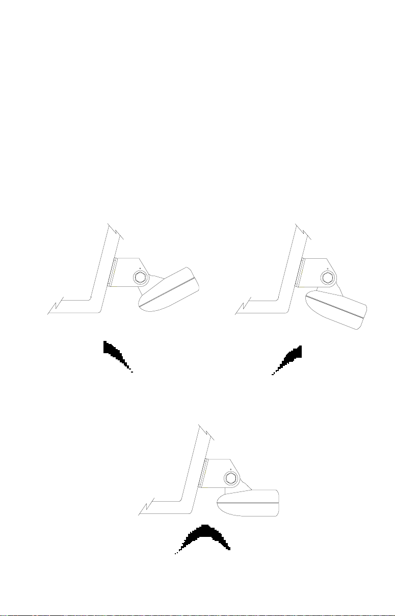
Fish Arches
If you do not get good fish arches on your display, it could be the
transducer is not parallel with the ground when the boat is at rest in the
water, or at slow trolling speeds. If the arch slopes up, but not back
down, then the front of the transducer is too high and needs to be
lowered. If only the back half the the arch is printed, then the nose of the
transducer is angled too far down and needs to be raised.
TRANSDUCER AIMED TOO FARTRANSDUCER AIMED TOO FAR
TRANSDUCER AIMED TOO FAR
TRANSDUCER AIMED TOO FARTRANSDUCER AIMED TOO FAR
BACKBACK
BACK
BACKBACK
PROPER TRANSDUCER ANGLEPROPER TRANSDUCER ANGLE
PROPER TRANSDUCER ANGLE
PROPER TRANSDUCER ANGLEPROPER TRANSDUCER ANGLE
TRANSDUCER AIMED TOOTRANSDUCER AIMED TOO
TRANSDUCER AIMED TOO
TRANSDUCER AIMED TOOTRANSDUCER AIMED TOO
FAR FORWARDFAR FORWARD
FAR FORWARD
FAR FORWARDFAR FORWARD
8
Page 11

POWER CONNECTIONS - HS-WSPC ONLY
NOTE! INSTALL THE TRANSDUCER BEFORE MAKING THE POWER CONNECTIONS!
The sonar unit works from a 12 volt DC system only. For the best results,
run the power cable directly to the boat’s battery. Keep the power cable
away from other boat wiring, especially the engine’s wires. This will give the
best isolation from electrical noise. If the supplied cable is not long enough
to reach the battery, splice #18 gauge insulated wire to it. You can attach
the power cable to an accessory or power buss, however, you may have
problems with electrical interference. Make certain to attach the in-line fuse
holder to the positive lead as close to the battery or terminal strip as
possible. This will protect both the unit and the power cable in the event of
a short.
WARNING!
Do not use this product without a 3-amp fuse wired into the power cable!
Failure to use a 3-amp fuse will void your warranty!
This unit has reverse polarity protection. No damage will occur if the power
wires are reversed. However, the unit will not work until the wires are
attached correctly.
For more information, consult your sonar unit's owner's manual.
TO SONAR UNIT
TO TRANSDUCER
BLACK
WIRE
12 VOLT
RED
WIRE
3 amp
FUSE
9
Page 12

If you installed the transducer on the transom, periodically wash the
transducer’s face with soap and water to remove any oil film that may
collect. Oil and dirt on the face will reduce the sensitivity or may even
prevent operation.
LITHO IN U.S.A. 988-0140-37
12
 Loading...