

Page 1
INSTALLATION AND OPERATION
INSTRUCTIONS
MODELS
HS-NS, HS-NSPC,HS-NS, HS-NSPC,
HS-NS, HS-NSPC,
HS-NS, HS-NSPC,HS-NS, HS-NSPC,
HS-WS-50, HS-WS-50D,HS-WS-50, HS-WS-50D,
HS-WS-50, HS-WS-50D,
HS-WS-50, HS-WS-50D,HS-WS-50, HS-WS-50D,
HS-WS-50/192HS-WS-50/192
HS-WS-50/192
HS-WS-50/192HS-WS-50/192
TRANSDUCERS
Page 2
The HS-NS and HS-NSPC are 192 kHz, 8 degree cone angle transducers. The HS-WS-50 and HS-WS-50D are 50 kHz, 36 degree cone
angle transducers. The HS-WS-50/192 is a dual frequency transducer
with 192 kHz, 20 degree and 50 kHz, 36 degree cone angle elements.
All are transom mount transducers. They can be installed on any
outboard or stern-drive powered boat. Do not use these transducers on
an inboard powered boat. The HS-NSPC has a power cable attached to
the connector. Follow the installation instructions for the power cable on
the back of this manual. Please install the HS-NSPC transducer before
wiring it's power cable.
Please read these instructions carefully before installing your transducer. The transducer mounting location is the most critical part of a
sonar installation. If it isn’t done properly, the sonar can’t perform to its
potential.
ASSEMBLYASSEMBLY
ASSEMBLY
ASSEMBLYASSEMBLY
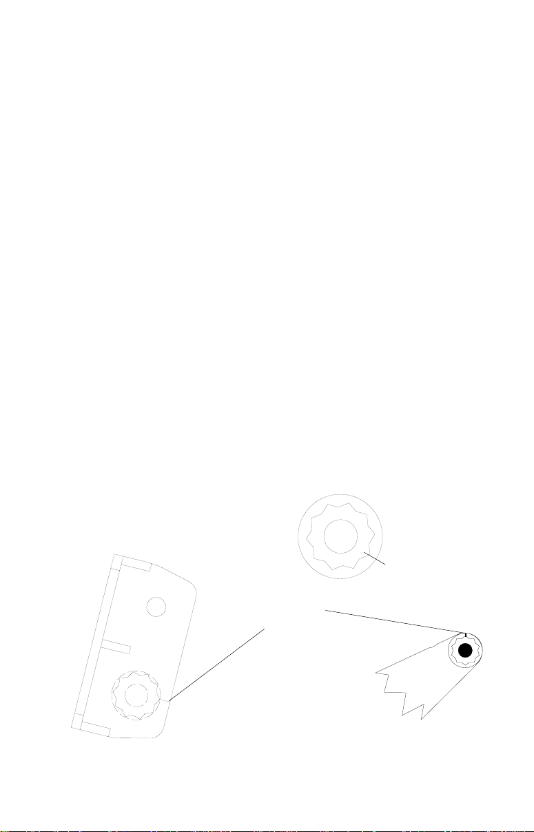
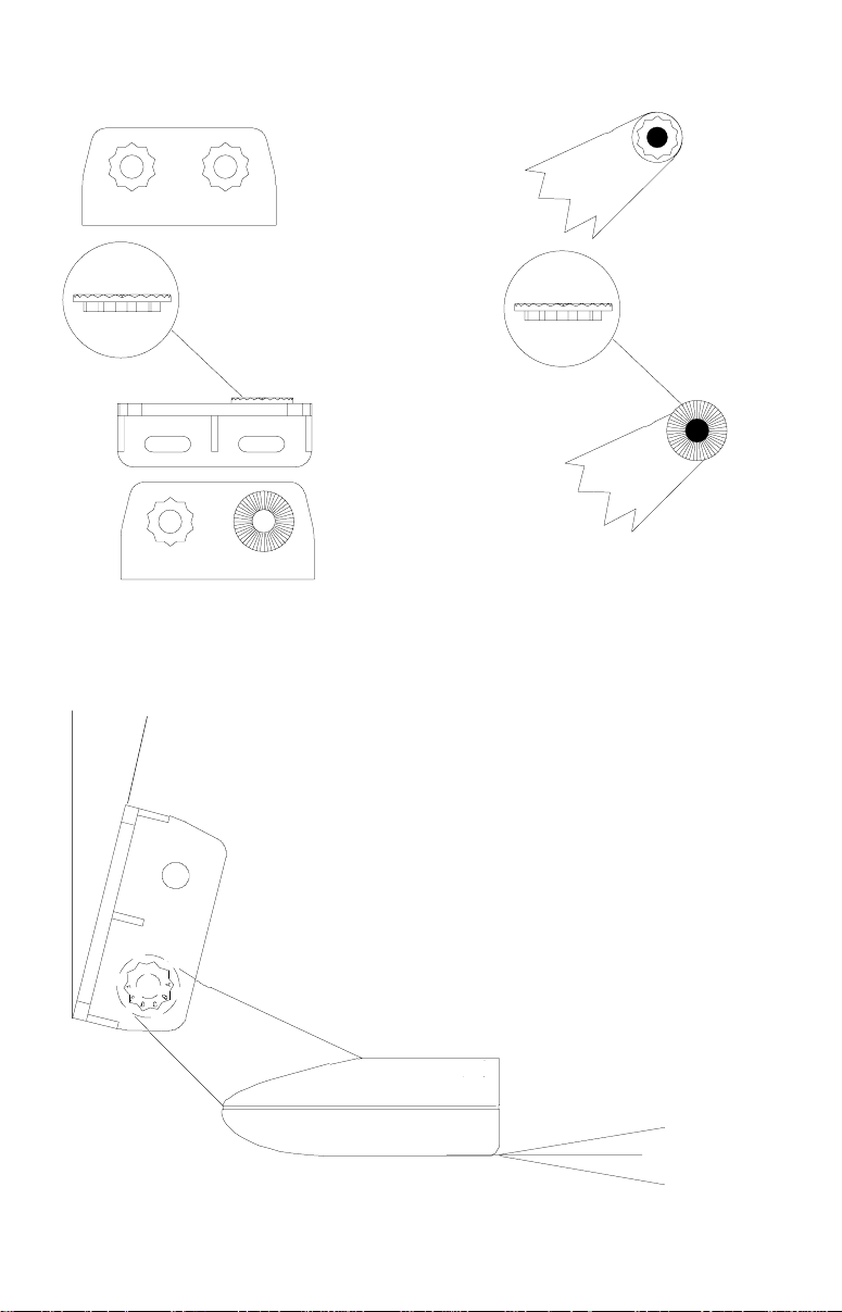
1. Locate the four ratchets in the transducer's hardware package. Note
there are letters engraved into one side of each ratchet. These are
for the coarse angle adjustment. A standard transom angle is 14
degrees. By aligning a letter on the ratchet to the alignment mark on
the the transducer bracket, the correct transducer angle can be
attained. Once you've determined the correct angle, press one
ratchet on each side of the transducer and one ratchet on each
transducer bracket as shown below.
RATCHET
ALIGNMENT
MARKS
F
A
E
D
B
C
TRANSDUCER
BRACKET
Copyright © 1996 Lowrance Electronics, Inc. All rights reserved.
F
E
TRANSDUCER
A
B
C
D
ALIGNMENT
LETTERS
1
Page 3
TRANSDUCER
BRACKET
TRANSDUCER
RATCHET
RATCHET
See the chart at the top of the next page for example transducer angles
for letter "A" at 12, 14, and 16 degree transom angles.
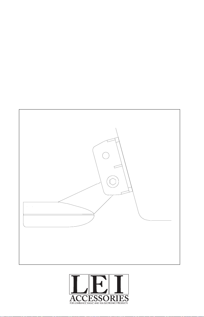
14
DEGREES
This is the way the transducer should look when it's
mounted on the transom.
2
o
-
o
+
ANGLE
OF
ATTACK
Page 4

12 DEGREE TRANSOM ANGLE12 DEGREE TRANSOM ANGLE
12 DEGREE TRANSOM ANGLE
12 DEGREE TRANSOM ANGLE12 DEGREE TRANSOM ANGLE
INDEX MARKS A-A A-B A-C A-D A-E
+37.0 +31.0 +40.0 +35.0 +28.0
ANGLE OF ATTACK +22.0 +16.0 +25.0 +20.0 +13.0
IN DEGREES +6.0 -1.0 +10.0 +4.0 -2.0
(REF. BOTTOM OF HULL) -9.0 -14.0 -5.0 -11.0 -17.0
PER RATCHET CLICK
14 DEGREE TRANSOM ANGLE14 DEGREE TRANSOM ANGLE
14 DEGREE TRANSOM ANGLE
14 DEGREE TRANSOM ANGLE14 DEGREE TRANSOM ANGLE
INDEX MARKS A-A A-B A-C A-D A-E
+39.0 +33.0 +42.0 +37.0 +30.0
ANGLE OF ATTACK +24.0 +18.0 +27.0 +22.0 +15.0
IN DEGREES +8.0 +3.0 +12.0 +6.0 0.0
(REF. BOTTOM OF HULL) -7.0 -12.0 -3.0 -9.0 -15.0
PER RATCHET CLICK
16 DEGREE TRANSOM ANGLE16 DEGREE TRANSOM ANGLE
16 DEGREE TRANSOM ANGLE
16 DEGREE TRANSOM ANGLE16 DEGREE TRANSOM ANGLE
INDEX MARKS A-A A-B A-C A-D A-E
+41.0 +35.0 +44.0 +39.0 +32.0
ANGLE OF ATTACK +26.0 +20.0 +29.0 +24.0 +17.0
IN DEGREES +10.0 +5.0 +14.0 +8.0 +2.0
(REF. BOTTOM OF HULL) -5.0 -10.0 -1.0 -7.0 -13.0
PER RATCHET CLICK
14 DEGREE
TRANSOM
ANGLE
For example, with a 14 degree transom, placing
the ratchet on the transducer bracket on "A" and
the ratchet on the transducer on "C" will result in
a +42.0 to -3.0 degree coarse angle adjustment
range.
o
-3.0
ANGLE
OF
ATTACK
o
+42.0
3
Page 5

LOCK
WASHER
BOLT
NUT
FLAT
WASHER
FLAT
WASHER
2. Once you've determined the proper ratchet placement, assemble the
transducer and bracket as shown above. Don't tighten the nut at this
time.
INSTALLATION - LocationINSTALLATION - Location
INSTALLATION - Location
INSTALLATION - LocationINSTALLATION - Location
1. The transducer must be placed in a location that has a smooth flow of
water at all times. Air bubbles created by the movement of the boat
hull against the water interfere with the sonar signal. This causes
“noise” or random marks to appear on the sonar’s display. You may
need to carefully view the water’s path at the transom while the boat
is moving to determine the best location for the transducer.
2. Make certain the chosen location doesn’t interfere with the boat’s
trailer. Mount the transducer at least one foot from the engine’s lower
unit. This will prevent air bubbles from the transducer interfering with
the propeller.
CAUTION!CAUTION!
CAUTION!
CLAMP THE TRANSDUCER CABLE TOCLAMP THE TRANSDUCER CABLE TO
CLAMP THE TRANSDUCER CABLE TO
CLAMP THE TRANSDUCER CABLE TOCLAMP THE TRANSDUCER CABLE TO
TRANSOM NEAR THE TRANSDUCER. THISTRANSOM NEAR THE TRANSDUCER. THIS
TRANSOM NEAR THE TRANSDUCER. THIS
TRANSOM NEAR THE TRANSDUCER. THISTRANSOM NEAR THE TRANSDUCER. THIS
WILL HELP PREVENT THE TRANSDUCERWILL HELP PREVENT THE TRANSDUCER
WILL HELP PREVENT THE TRANSDUCER
WILL HELP PREVENT THE TRANSDUCERWILL HELP PREVENT THE TRANSDUCER
FROM ENTERING THE BOAT IF IT ISFROM ENTERING THE BOAT IF IT IS
FROM ENTERING THE BOAT IF IT IS
FROM ENTERING THE BOAT IF IT ISFROM ENTERING THE BOAT IF IT IS
KNOCKED OFF AT HIGH SPEED.KNOCKED OFF AT HIGH SPEED.
KNOCKED OFF AT HIGH SPEED.
KNOCKED OFF AT HIGH SPEED.KNOCKED OFF AT HIGH SPEED.
CAUTION!CAUTION!
GOOD LOCATIONGOOD LOCATION
GOOD LOCATION
GOOD LOCATIONGOOD LOCATION
4
Page 6

POOR LOCATIONPOOR LOCATION
POOR LOCATION
POOR LOCATIONPOOR LOCATION
GOOD LOCATIONGOOD LOCATION
GOOD LOCATION
GOOD LOCATIONGOOD LOCATION
POOR ANGLEPOOR ANGLE
POOR ANGLE
POOR ANGLEPOOR ANGLE
GOOD LOCATIONGOOD LOCATION
GOOD LOCATION
GOOD LOCATIONGOOD LOCATION
3. Don’t mount the transducer directly behind strakes or ribs on the
bottom of the hull. Typically, a good location on aluminum boats is
between the ribs closest to the engine.
4. Once you determine the best location for the transducer, hold the
bracket against the transom. The transducer should be roughly
parallel to the ground. The bottom of the hull should be about
halfway between the centerline of the transducer and its bottom.
(See the illustration below.)
Mark the transom in the center of each slot in the transducer bracket.
Now drill one hole in the center of each slot. Use #12 stainless steel
screws (not included) to loosely attach the brackets to the transom.
5. Adjust the transducer and bracket so that the front of the transducer
is slightly lower than the back. See the section on fish arches in this
manual for proper transducer angles. Tighten all screws. Clamp the
transducer cable to the transom close to the transducer. This will
prevent the transducer from entering the boat should it be knocked
off at high speed.
5
Page 7

6. Route the transducer cable to the sonar unit. Keep the transducer
cable away from other wiring on the boat, if possible. Electrical noise
from engine wiring or bilge pumps can be picked up on the transducer cable. This can show up as unwanted interference on the
sonar display.
FLAT-BOTTOM HULLFLAT-BOTTOM HULL
FLAT-BOTTOM HULL
FLAT-BOTTOM HULLFLAT-BOTTOM HULL
DEEP-"VEE" HULLDEEP-"VEE" HULL
DEEP-"VEE" HULL
DEEP-"VEE" HULLDEEP-"VEE" HULL
NOTE: Some aluminum boats with strakes or ribs on the outside of the
hull create large amounts of turbulence at high speed. These boats
typically have large outboard motors capable of propelling the boat at
speeds over 35 mph. The transducer should be mounted as far below
the hull as possible on these boats. This will place the face of the
transducer below the turbulent water, allowing the sonar unit to work at
high speeds.
7. Make a test run to determine the results. If there is interference on
the display when running the boat at high speed, try lowering or changing the angle of the transducer.
NOTE
Periodically wash the transducer's face with soap and water to
remove any oil film. Oil and dirt on the face will reduce the
sensitivity or may even prevent operation.
CAUTION!
MAKE CERTAIN TO CLAMP THE TRANSDUCER CABLE TO
THE TRANSOM NEAR THE TRANSDUCER. THIS WILL HELP
PREVENT THE TRANSDUCER FROM ENTERING THE BOAT IF
IT IS KNOCKED OFF AT HIGH SPEED.
6
Page 8

POWER CONNECTIONS - HS-NSPC ONLY
NOTE! INSTALL THE TRANSDUCER BEFORE MAKING THE POWER CONNECTIONS!
The sonar unit works from a 12 volt DC system only. For the best results,
run the power cable directly to the boat’s battery. Keep the power cable
away from other boat wiring, especially the engine’s wires. This will give the
best isolation from electrical noise. If the supplied cable is not long enough
to reach the battery, splice #18 gauge insulated wire to it. You can attach
the power cable to an accessory or power buss, however, you may have
problems with electrical interference. Make certain to attach the in-line fuse
holder to the positive lead as close to the battery or terminal strip as
possible. This will protect both the unit and the power cable in the event of
a short.
WARNING!
Do not use this product without a 3-amp fuse wired into the power cable!
Failure to use a 3-amp fuse will void your warranty!
This unit has reverse polarity protection. No damage will occur if the power
wires are reversed. However, the unit will not work until the wires are
attached correctly.
TO TRANSDUCER
BLACK
WIRE
12 VOLT
RED
WIRE
3 amp
FUSE
LITHO IN U.S.A. 988-0140-26
5
 Loading...