

Page 1
EAGLE MICROSYSTEMS. INC.
Instrumentation for Measurement and Control
Premier Series Monitor
GD-1000 GAS DETECTOR
INSTALLATION AND OPERATION
MANUAL
SENSOR
IHPN 630600
EAGLE MICROSYSTEMS, INC.
366 Circle of Progress
Pottstown, PA 19464
PHONE: 610-323-2250 FAX: 610-323-0114
1 copyright 2/02
Page 2
EAGLE MICROSYSTEMS. INC.
2
3
4
Instrumentation for Measurement and Control
Premier Series Monitor
TABLE OF CONTENTS:
SPECIFICATIONS: Page 2
QUICK START: Installing, wiring and display operation. Page 2
OPERATION: Main run screen, password entry screen and monitor setup screen. Page 3
ALARM: Critical and danger screens. Page 3/4
CALIBRATION: Analog input (CH1), Analog output (IOUT). Page 4/5
BATTERY BACKUP: Battery status Page 5
WIRING: Power, alarms, analog input and outputs Page 6
SPECIFICATION:
Power Supply 115/230 VAC Switch selectable.
Power Consumption 12W
Display LCD, backlit, 16 characters by 2 lines, 5mm character height,
5x8 character matrix.
Pushbuttons Four, tactile dome.
Relays Three, Mechanical (AC or DC)
Buzzer. 103 DB
Rating 1.2A, 125VAC.
Optional: 5A @ 250VAC.
Analog Input two, 4 to 20mA.
Analog Output Isolated 4 to 20mA, 0-500ohm load, active.
Digital Output 20mA Serial (remote computer)
QUICK START
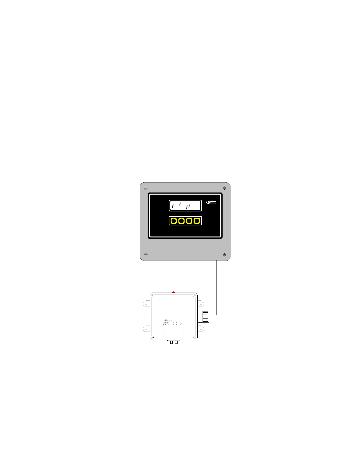
INSTALLATION:
1). Mount the Premier Series Monitor at eye level. Mount the sensor 12” off the
floor. The Premier Series Monitor is provided with 12’ of cable for the sensor.
2). Attach the cable from the Premier Series Monitor to the sensor. The
red LED will go on when powered up.
3). The Premier Series Monitor requires 117VAC (+/-10%) power at 48-62Hz
and 1/4 amp.
IHPN 630600
SENSOR
After proper installation the monitor is ready to operate
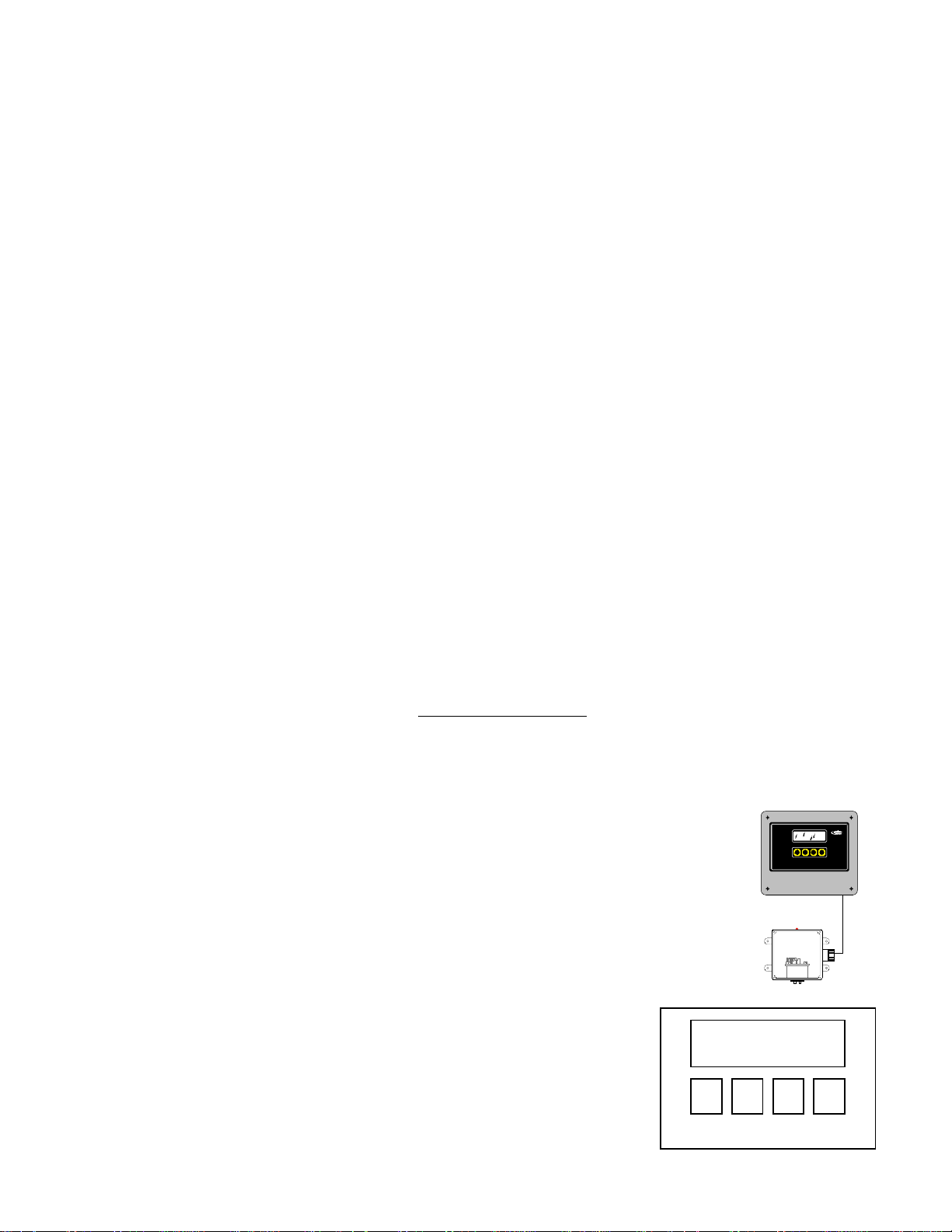
DISPLAY:
The top line of the LCD display is formatted to show a selected value along with
its engineering units. The second line normally provides function labels for
the four pushbuttons located below the function. The pushbuttons do not have
any labels.
.
Line1: Value &
units
1
2 copyright 2/02
Page 3

EAGLE MICROSYSTEMS. INC.
Instrumentation for Measurement and Control
Premier Series Monitor
OPERATION:
MAIN RUN SCREEN:
The value displayed is the type of sensor and its scaled output in ppm.
Below the sensor type and value is a fifty segment bar-graph representation
of the monitors full scale and the 4mA to 20mA output (PO1). To enter the
configuration and calibration screens press SET. The display will prompt
you to enter a password.
1
2
3
4 SET Press SET to enter a password screen.
PASSWORD ENTRY SCREEN:
From the run screen, press SET and the user will be prompted to enter a
password (default is 000). If the password is correct, the MONITOR SETUP
SCREEN will be displayed. If an incorrect password is entered, The MAIN
RUN SCREEN will be displayed.
1 ?, 0-9 Steps from 0 to 9 and then back to 0.
2 ?, 0-9 Steps from 0 to 9 and then back to 0.
3 ?, 0-9 Steps from 0 to 9 and then back to 0.
4 ENT Press ENT to enter monitor setup screen..
SO2 0.0 ppm
IIIIIIIIIIIIIIIIIIIIIIIIII SET
ENTER PASSWORD
???ENT
MONITOR SETUP SCREEN:
From the Monitor Setup screen, you can select CAL, ALM or RUN. The
Calibration screen provides the ability to calibrate the analog input and
output. The alarm screen provides the ability to set the Danger and Critical
values.
1 CAL Enter calibration screen.
2 ALM Enter danger and critical alarm setup screen
3
4 RUN Go back to the main run screen.
Premier Series Monitor
ALARM:
SELECT ALARM:
From the MONITOR SETUP SCREEN, press the pushbutton under ALM.
1 CAL Enter calibration screen
2 ALM Enter alarm select screen
3
4 RUN Go back to the main run screen
MONITOR SETUP
CAL ALM RUN
MONITOR SETUP
CAL
ALM
RUN
3 copyright 2/02
Page 4

EAGLE MICROSYSTEMS. INC.
Instrumentation for Measurement and Control
ALARM SCREEN:
Press the pushbutton under CRT or DGR, to configure. Press ESC to return.
1 CRT Critical alarm screen to set value for relay contact.
2 DGR Danger alarm screen to set value for relay contact.
3
4 ESC Go back to the monitor setup screen.
CRITICAL ALARM SETUP SCREEN:
From the critical alarm setup screen you can view the current value. To
change, press the pushbutton under UP or DWN to change the value. Press
the pushbutton under SET to enter the new value and return back to alarm
setup screen.
1UPTo increase the value.
2 DWN To decrease the value.
3
4 SET Go back to the alarm setup screen.
DANGER ALARM SETUP SCREEN:
From the danger alarm setup screen you can view the current value. To
change, press the pushbutton under UP or DWN to change the value. Press
the pushbutton under SET to enter the new value and return back to alarm
setup screen
1UPTo increase the value.
2 DWN To decrease the value.
3
4 SET Go back to the alarm setup screen.
SEL SO2 CH1 ALM
CRT DGR ESC
CRITICAL 10.0
UP DWN SET
DANGER 2.0
UP DWN SET
Premier Series Monitor
SELECT CALIBRATION
From the MONITOR SETUP SCREEN, press the pushbutton under CAL.
1 CAL Enter calibration screen..
2 ALM Enter alarm select screen.
3
4 RUN Go back to the main run screen
CALIBRATION SCREEN:
Press the pushbutton under CH1 or IOUT. Press ESC to return.
1 CH1 Press to calibrate 4-20mA analog input..
2
3 IOUT Press to calibrate 4-20mA analog output.
4 ESC Will ask to set new password yes /no
CALIBRATION:
MONITOR SETUP
CAL
ALM RUN
CALIBRATION
CH1
IOUT ESC
4 copyright 2/02
Page 5

EAGLE MICROSYSTEMS. INC.
Instrumentation for Measurement and Control
CALIBRATE ANALOG INPUT CH1 SCREEN:
A device generating a calibrated 4-20mA output is required. The current
analog input is displayed in the top right of the screen. Use a calibrated
analog input or other device to calibrate the zero and full scale value.
1 ZRO Press to enter the value being input as the calibrated zero.
2 SPAN Press to enter the value being input as the calibrated standard.
3
4 ESC Go back to the calibration screen.
SET CH1 0.0ppm
ZRO SPAN ESC
CALIBRATE ANALOG OUTPUT IOUT SCREEN:
A DMM is required to proceed with calibration. Attach a DMM, press the
pushbutton under 4mA or 20mA to enter setup screen.
1 4mA Press to enter 4mA setup screen.
2 20mA Press to enter 20mA setup screen.
3
4 EXIT Go back to the CALIBRATION screen.
SET ANALOG OUT
4mA 20mA EXIT
SET 4.0mA ANALOG OUTPUT:
A DMM is required to proceed with calibration. While viewing the DMM,
press the pushbutton under up or down to new value. Press the pushbutton
under SET to enter the new value and return back to set analog output screen.
1UPPress to drive analog output up. View on DMM.
2 DWN Press to drive analog output down, View on DMM.
3
4 SET Press SET to enter the new value and return to SET ANALOG OUT screen.
SET 4.00mA OUT
UP DWN SET
SET 20.0mA ANALOG OUTPUT:
A DMM is required to proceed with calibration. While viewing the DMM,
press thepushbutton under UP or DWN to new value. Press the pushbutton
under SET to enter the new value and return back to Set Analog Output
screen.
1UPPress to drive analog output up. View on DMM.
2 DWN Press to drive analog output down, View on DMM.
3
4 SET Press SET to enter the new value and return to set analog output screen.
SET 20mA OUT
UP DWN SET
Premier Series Monitor
BATTERY STATUS:
MAIN RUN SCREEN:
If the monitor is equipped with the battery backup option the battery status can
be displayed from the main run screen. To display battery status depress #1
pushbutton. When pressed the battery status will be displayed for 30 sec.
After 30 sec. The display will revert to the Main Operate Screen.
1 Press to display battery status. In battery power mode, hold to power down.
2
3
4
BATTERY STATUS
E IIIIIIIIIIIIIIIII F
5 copyright 2/02
Page 6

EAGLE MICROSYSTEMS. INC.
Instrumentation for Measurement and Control
Premier Series Monitor
TERMINATIONS:
F1
FUSE
TB5
G
1
POWER
AC
N
2
H
3
TB4
1
SW
2
motor
3
4
K1 K2 K3 K4
1
TB1
K1 K2 K3 K4
POWER:
TB5
G
1
POWER
AC
N
2
H
3
ALARMS:
1
TB1
K1 K2 K3 K4
8234567
1
TB2
+ -
Tx
COM
4-20mA
P01
PS-1000
19
5
TB3
+ - + -+ - + -
+ -
Rx
12V
SCR
PV1
4-20mA
+ -
+ - + -
PV2
A B
mV
CELL
THRM
8234 56 7
WIRING:
PASS
FAILURE
CRITIAL SENSOR 1
DANGER
TB5
K4
K3CRITIAL SENSOR 2
K2
K1
G
N
H
GROUND
NUTERAL
HOT
TB1
(8)
(7)
(6)
(5)
(4)
(3)
(2)
(1)
LOAD
LOAD
LOAD
LOAD
H
N
SENSOR INPUT:
1
TB3
+ - + -+ - + -
+ -
+ -
+ - + -
4-20mA
12V
SCR
PV1
PV2
mV
CELL
9
A B
THRM
PV1
PV2
SCR
12V
-
-
+
+
TB3
(1)
(2)
(3)
(4)
(5)
+
SENSOR
1
+
SENSOR
2
-
ANALOG OUTPUT:
1
TB2
+ -
4-20mA
P01
COM
5
Tx
Rx
PO1
4-20mA OUTPUT
<= 500Ω
TB2
+
(1)
-
(2)
6 copyright 2/02
 Loading...