

Page 1
4<
H
I
I
FISH
AND
FISH
INSTALLATION
INSTRUCTIONS
LITHO IN U.S.A. 988-0106-31
PDF compression, OCR, web-optimization with CVISION's PdfCompressor
EAGI
I.D. PLUS
I.D.
AND OPERATION
Page 2
TABLE OF CONTENTS
INTRODUCTION
INSTALLATION 1
POWER
NOISE
TRANSDUCER 3
KEYBOARD BASICS 4
OPERATION 7
SENSITIVITY 7
CHARTSPEED
RANGE
ZOOM
DIGITAL 11
FISH I.D. FEATURE 12
AUTO 13
ALARMS 13
CHARTALARM 14
FISH ALARM
SPEAKER
LIGHT 15
MODE 16
TRANSDUCERS AND
SIGNAL INTERPRETATION 21
FISH ARCHES 21
WATER TEMPERATURE AND THERMOCLINES 23
SURVEYING A LAKE 24
BAIT FISH 25
HOW TO OBTAIN SERVICE 25
SPECIFICATIONS 26
GLOSSARY 26
CONNECTIONS 1
CONE ANGLES 20
1
3
10
10
15
15
SECOND ECHO
of a
depth
the
again,
SECOND FUNCTION KEY
primary keys
SENSITIVITY
Increasing
called
SCROLL SPEED - See CHART SPEED.
SHOOT-ThROUGH-HULL
sonar
target
bottom, striking
and
returning
the
"gain".
signals
-
Another echo that
echo. This is caused
the surface of the
to the surface.
-
A button that converts the functions of the
to other functions.
-
The
sensitivity
to
pass through a fiberglass
of a sonar unit's receiver to
ability
allows weaker
-
A transducer installation
by
the hull.
SUPPRESSION
interference or noise.
SURFACE CLARITY
signals displayed
THERMOCLINE
cool
layers
fish
prefer.
TRANSDUCER
electrical
When a return echo strikes the
into electrical
-
A method used in some sonar
CONTROL - Reduces or eliminates undesirable
near the water's surface. Also called "SCC".
-
A
of water caused
layer
of water. The thermocline
-
The element of a sonar
energy
from the transmitter into ultrasonic sound waves.
transducer,
energy
which is received and
provides
registers
the sound waves
water,
targets
hull without
by
it
at
roughly
reflecting
travelling
to be
units to
the
meeting
the
system
converts the sound waves
displayed by
to the bottom
display targets.
displayed.
which allows the
cuffing
help
of warm and
temperature
that
converts the
the sonar unit.
twice the
off
Also
a hole in
eliminate
most
TRANSOM MOUNT
sensors on the transom of the boat.
UPPER/LOWER LIMIT - These are the
sonar screen or
while the lower limit is
has 20 feet as the
range
Copyright
All features and
©
1989,
All
rights
specifications subiect
Eagle
reserved.
Electronics
to
change
display,
foot
without notice.
PDF compression, OCR, web-optimization with CVISION's PdfCompressor
-
paper.
A method of
The
upper
at the bottom. For
limit and 30 feet as the lower limit.
upper
mounting
range
limit is shown at the
29
transducers or other
limits
displayed
example,
on the
of the
top
a 20 to 30
Page 3
-
LCD
Graph
LCG
NOISE
ignitions systems,
of the
display
OPERATING FREQUENCY-
and receiver.
Liquid crystal display.
sonar instrument.
-
Liquid Crystal Graph.
-
Any
engine
undesired
radios,
or other mechanical sources.
signal.
etc. Acoustic noise is caused
as random dots or lines.
(See kHz.)
The screen
Electrical
Frequency
or
display
noise is caused
of a
Noise
Liquid Crystal
by engine
the vibration
by
appears
on the
of a sonar unit's transmitter
INTRODUCTION
Welcome to the world of
Fish 1.0. Plus are
high quality
sportfishing
sonar
novice users. These units have
displays
with
conditions to
(Note:
the same
the bottom
Fish
your
All
operating
except
depth,
1.0.,
the most from
get
instructions for the
for
has those functions. To
1.0. will also hold true for the Fish 1.0. Plus.
fish,
can "fine tune"
you
speed
and
simplify
sonar. Your
designed
an automatic feature that finds and
and structure.
sonar.
your
Fish l.D. and Fish 1.0. Plus are
temperature.
this
manual,
Eagle
for both
As
you
the unit to the
Only
Fish l.D. and
professional
become familiar
surrounding
Fish l.D. Plus
the
all references to the Fish
and
-
OUTPUT POWER
The
amplitude
the sonar unit to the transducer.
output power,
displayed.
the
deeper
PIXEL - The small dots or
PIXEL DENSITY
crystal
display. Typically,
-
a sonar unit can
squares
The number of
the
of electrical
Measured in
read,
on a
liquid crystal display
pixels per square
greater
number of vertical
energy
transmitted from
watts,
and more detail can be
better the resolution.
PULSE LENGTh
measured in micro-seconds. The shorter the
the resolution. For
-
The amount
example,
of time that the sonar transmits. This is
pulse length,
micro-second
a 30
pulse
length
a one inch resolution.
RANGE The section of water shown on the sonar
example,
a 60 foot
range
has zero for the
upper
limit and 60
lower limit.
REMOTE
from
ceiver.
operate separately
RESOLUTION
each other or from the bottom.
SCALE
depth
the scale markers on the
-
An
intelligent "repeater"
unit that receives
depth
another sonar unit. A remote doesn't have a transmitter
However,
it does have it's own features that are
from the master.
-
The
ability
-
The
markings
of a
target, simply compare
on a sonar unit's
display.
sonar unit to
of a
the
display.
target's
separate targets
To determine the
location 10 the
the
higher
or CAT.
on a
inch
pixels,
the better
is
display.
information
adjustable
location of
the
liquid
the
equal
For
for the
or re-
and
from
to
To
This is where it all
down the road. After
Fish
when
this
started with
get
begins,
read the rest of this manual in detail. The
l.D.,
to the
get
you
manual for reference when
your
you've
water,
Fish
and
first read
l.D.,
improper
read these instructions and installed
the more
your
head for the water.
you
INSTALLATION
Mounting
Install the unit in
when tilted for the best
wood screw or
back of thin
there is
through
panels
enough
convenient
any
viewing angle.
bolt
mounting.
to secure the
room behind
location, provided
mounting
the unit to attach the
transducer cables.
You can route the
power
hole in the base of the
in the
mounting
through
up
wire down
surface. First
the hole and
through
the bracket and dash. After
and transducer
gimbal
bracket. Then
pass
gimbal
bracket. Then
the transducer connector and cable
the hole with silicone rubber adhesive
cover the
majoilty
Power Connections
The Fish l.D.
cable to an
electrical
interference,
of the hole.
operates
accessory
from a 12 volt
battery system.
or
power
buss.
then attach the
the installation section.
installation can
Fish 1.0. will do for
Holes in the bracket base allow
Place a
piece
hardware. Make certain
cables
pass
(RTV).
If
you
cable
directly
cause
problems
your
more
you
you.
know
Take
there is clearance
of
through
them
the
push
routing
plywood
through
the
on the
power
and
the one inch
a hole
power
cable
cables,
Offset the bracket to
Attach the
have
problems
to the
power
with
battery.
fill
PDF compression, OCR, web-optimization with CVISION's PdfCompressor
28
1
Page 4
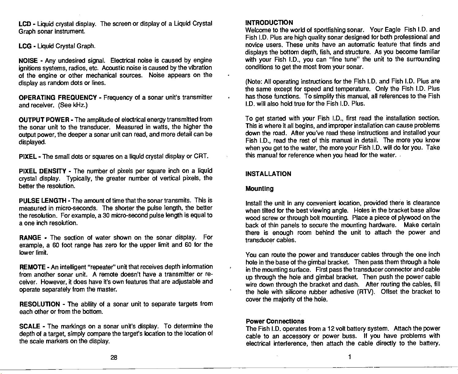
Electrical interference shows as random dots on the
the boat's
The
negative
power
attaches to the
enough, splice ordinary
holder is as close to the
possible.
short. Use a
These units have reverse
the
power
wires are attached
engine
power
or
cable with
This
wires are reversed.
or an
accessory
cable has two
ground.
3-amp
Attach the in-line fuse holder to the red wire on the
the
crimp
battery
protects
or
#18
the
fuse.
correctly.)
is on.
wires,
connector. The other end of the fuse holder
power
polarity protection.
red is the
accessory
source
power
(However,
wire onto it. Be certain that the fuse
cable and
gauge
positive
buss. If
(battery
the cable is not
or
accessory buss)
unit in the event of a
your
No
damage
the unit will not work until the
display
lead and black is
whenever
long
as
will occur if
CONE ANGLE
transducers available with cone
varying
CRT
DEFINITION - The
display
definition.
DISCRIMINATION
paper graphs
needs of fishermen.
-
Abbreviation for Cathode
with
-
high
that
of the transducers cone of sound.
Angle
angles
Tube. See Video
Hay
of a sonar unit's
ability
definition can show more detail than one with low
-
A feature available on
separates
false echoes from
tion. The Discrimination feature on
many
sources,
false
signals
and more.
from other
sonars,
from 8 to 45
display
Eagle
true
Eagle
sonar units
acoustic and
has
Eagle
degrees
to suit the
Graph.
to show detail. A
LC.G.'s and
informa-
target
removes
electrical
r
FROM
SPEED/TEMP
SENSOR
12
VOLT
BATrERY
FISH l.D.
FUSE
HOLDER
FISK LD.
12 VOLT
BAIlERY
PLUS
FUSE
FISH ALARM
is detected.
FISK ARCH
suspended
are
typically fish,
information.
FLUSH MOUNT
transducer flush with the bottom of the hull.
GIMBAL BRACKET
nently.
angle.
GRAYLINE
played
displayed
composition
soft or hard. A hard bottom returns
line. A
emphasized
IN-DASH
Usually,
kHz
ates at 192 Kilohertz.
on the screen.
-
Kilohertz. A measurement of
-
An alarm that activates when a fish or
-
A sonar with
targets
The sonar unit can rotate in the bracket for
in
of the bottom. In other
soft, muddy
-
A sonar unit
the face of the sonar
as
upside
hence the name "Fish Arch". See
-
A transducer that is installed with
-
A bracket used to install a sonar
This feature shows the relative
Signals
black,
stronger targets
or
weedy
with a narrow
gray
installed
(192,000 cycles per
resolution and definition can
good
down "Vees" or arches. These
weaker than the GRAYLINE
are
gray.
words, you
a
strong signal
bottom returns a weaker
line.
through
is flush or
nearly
frequency.
suspended object
display
signals
20 for more
page
the bottom of the
unit
perma-
the best
strength
It
also
can tell if
a hole in the boat's dash.
of
gives
causing
signal
viewing
setting
which is
dis-
are
gray
signals
clues to the
the bottom is
a wide
so with the dash.
Your
second).
Eagle
sonar
oper-
2
27
PDF compression, OCR, web-optimization with CVISION's PdfCompressor
Page 5
SPECIFICATIONS
Dimensions
Weight
Transmitter
Output
Receiver
Operating
Operating
Number of
Display
Maximum
Maximum
frequency
Power
(typical)
Sensitivity
Current
Voltage
pixels
Scroll
Speed
Chart
Digital Range
Range
5 7/8"H x 7 3/4"W
1
3/4
pounds
192 kHz
275 watts
watts RMS
34.4
82 db
temperature
200 ma
500
(lights off)
ma
(lights on)
9-15 vdc
27
50 x
per
per
x
minute
minute
(vertical
1350 Total
.5"
32"
180 feet
400 feet
to
peak
horizontal)
(minimum)
(maximum)
x 3 7/16"D
peak
stabilized
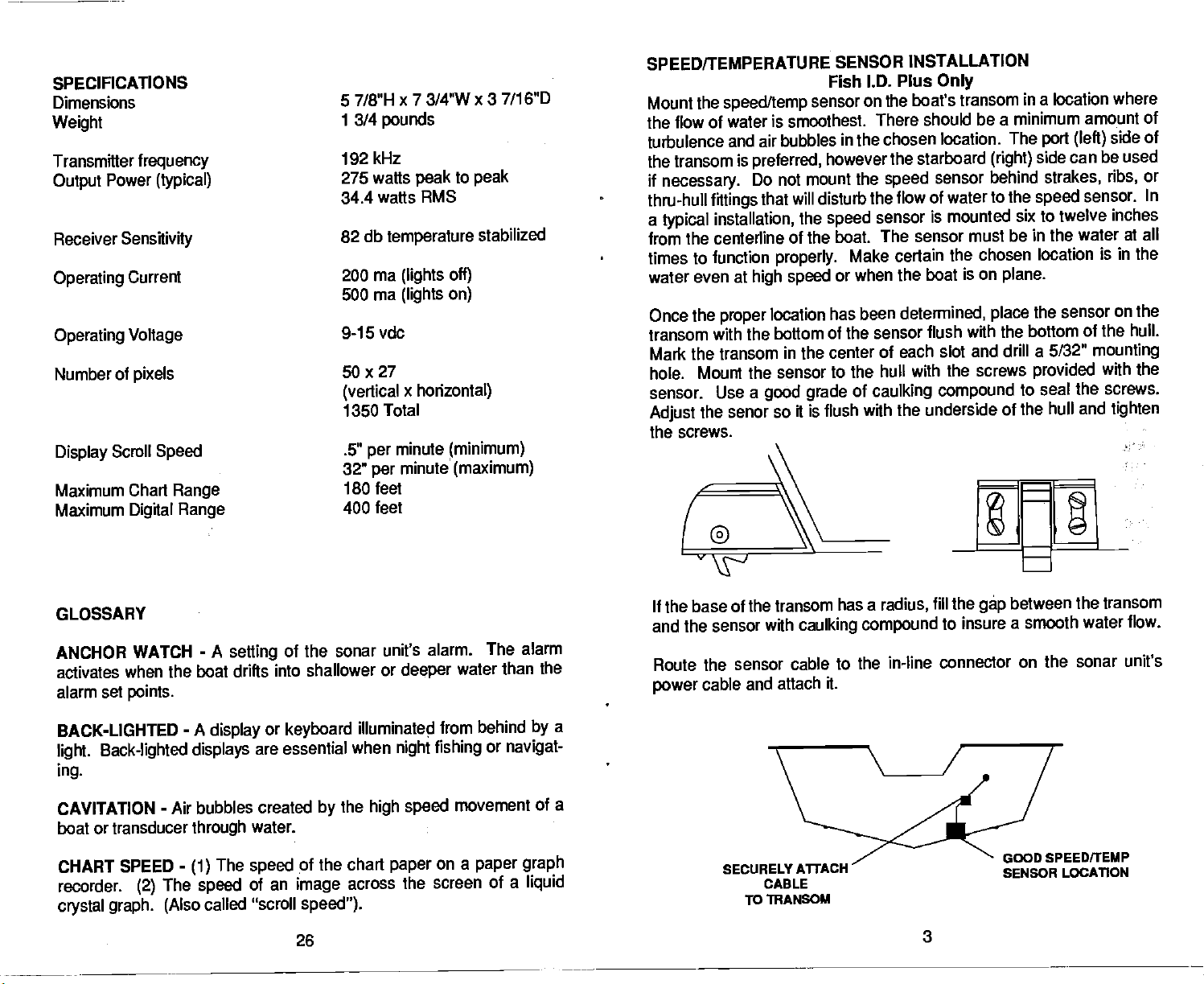
SPEED/TEMPERATIJ
Mount the
the flow of
turbulence
the transom
if
necessary.
thru-hull
a
typical
from the centerline
times to function
water even at
Once the
transom
Mark
hole.
sensor. Use
Adjust
speed/temp
water is smoothest. There
and air bubbles in the
is
preferred,
Do not mount the
fittings
that will disturb the
installation,
of the boat.
properly.
high speed
proper
location has been determined,
with the bottom of the sensor
the transom in the center
Mount the sensor to the
a
good grade
senor so it is flush with
the
the screws.
RE SENSOR
Fish l.D. Plus
sensor on
however the
the
speed
sensor
The sensor must be in the water
Make certain
or when the
of each slot and drill a 5/32"
hull with the screws
of
caulking compound
INSTALLATION
Only
the boat's transom
should be a
in
a
minimum amount of
chosen location. The
starboard
speed
sensor behind
flow of water to the
(right)
side can
speed
is mounted six to twelve
the chosen location is
boat is on
flush with the
plane.
the sensor
place
bottom of the hull.
provided
to seal
the underside of the hull
location where
port (left)
side of
be used
strakes, ribs,
sensor.
inches
in the
on the
mounting
with the
the screws.
and
tighten
or
In
at all
If
base of the transom has a radius,
GLOSSARY
-
ANCHOR WATCH
activates
alarm
when the boat drifts
set
points.
BACK-LIGHTED
Back-lighted displays
light.
ing.
CAVITATION
-
boat or transducer
CHART SPEED
recorder.
(2)
crystal graph. (Also
A
setting
-
A
display
Air bubbles created
through
-
The
(1)
The
speed
called "scroll
PDF compression, OCR, web-optimization with CVISION's PdfCompressor
of the sonar unit's
into shallower or
or
keyboard
are essential
the
by
water.
pf the chart
speed
of an
image
speed").
26
illuminated
when
high speed
across
alarm. The alarm
deeper
water than the
from behind
fishing
night
movement of
on a
paper
paper
the screen of
or
navigat-
a
a
by
a
graph
liquid
the
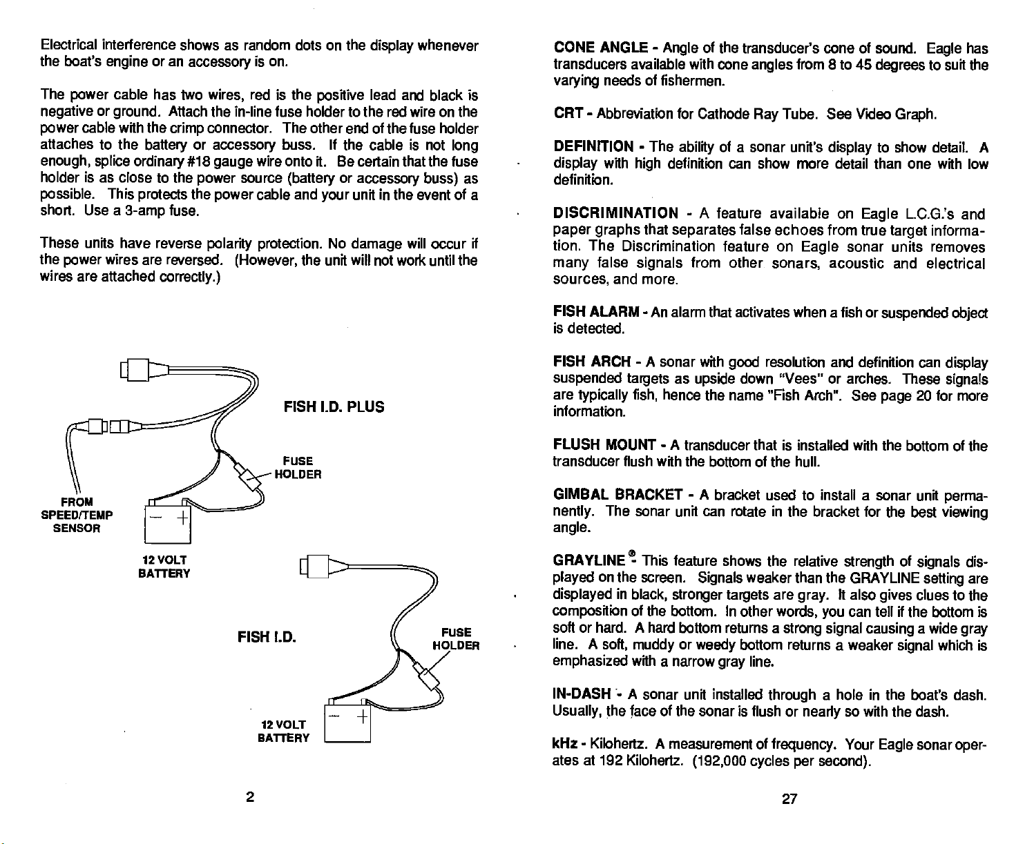
and the sensor with
Route the
power
sensor cable to the
and attach it.
cable
SECURELY
CABLE
To TRANSOM
caulking
A1TACH
compound
fill the
to insure a
in-line connector on the
3
between the transom
gép
smooth water flow.
sonar unit's
GOOD SPEEDITEMP
SENSOR LOCATION
Page 6

BAIT
FISH
The
importance
sized.
Bait
shad. Bait fish can also be
bluegill,
They
fish are the
and bass.
of bait fish to
are the
principal
plankton
successful
food of all
feeding forage fish,
the
young
fishina can't be over-emoha-
game
of
game fish,
fish in
most waters.
such as minnows and
such as
crappies,
KEYBOARD
This section
Operation
Fa.—]
L I
section for
ON OFF
These
simply press
Pressing any key generates
________
that
BASICS
a brief
gives
a detailed
keys
the unit has
explanation
description
turn the unit's
the ON
key.
accepted
of the
power
To turn it
keyboard.
of
each
on and off. To turn it
off,
a tone or
a command.
key's operation.
the OFF
press
"beep."
This tells
Read the
on,
key,
you
Most bali fish
promotes
of
fishing
will look
nearby,
HOW TO
If
have a
you
before
help
Service
homa
residents call
Please detail the
ment
may
If
the unit must be
is
advisable to insure
concentrate within five feet of the
the
growth
is to use the unit to
like a "cloud" on the
often
directly
OBTAIN SERVICE
problem
sending
Department
be able to
of
the
plankton
on which
find the bait fish first. A
unit's
beneath the
with
your
it in for
at
repair.
1-800-331-2301,
display. Usually, game
school of bait fish.
sonar
unit,
Call
please give
or write the
extension
918-7-1,extension 401,
problem
save
returned,
the unit in case it's lost or
are
you
you
pack
experiencing.
the inconvenience of
it
carefully
so it
surface where
feed. One method
they
school of bait fish
us a
Factory
toll
401,
collect.
free. Okla-
The service
returning your
won't be
damaged
damaged.
during
sunlight
fish will be
chance to
Customer
depart-
unit.
It
transit.
UP and
These
function
chart
DOWN ARROWS
are used to
keys
on the unit. Use these
speed,
range,
zoom and
4
adjust
keys
chart alarm.
virtually every
to
adjust
the
feature
sensitivity,
and
Eagle
12000 E.
Tulsa,
Mail To:
Customer
Skelly
01< 74128
25
Service
Drive
PDF compression, OCR, web-optimization with CVISION's PdfCompressor
Page 7

Schooling
stay.
provides
here.
this
temperature.
fish
suspended
over
deep
We assume
they
water
are the
lie at the level that
most comfortable
The
temperature
bottom.
Layers
warm and cool
thickness of the thermocline
lakes there
deep
are
important
active.
game
Many
fish
will
of water in the lake is seldom constant
of different
of water is called a thermocline. The
layer
may
fishermen because
to
times bait
suspend
temperatures
can
be two
or more at different
fish will be above the thermocline while
in or
just
with the season or time of
vary
below it.
The Fish l.D. and l.D. Plus can detect
but the
SURVEYING
The
day
that
where,
any
sensitivity
most successful
after
day
produce
and at what
season. And
throughout
factors.
other
With the
Fish
will
probably
A LAKE
anglers
and
year
fish
consistently. They
depth, they
they
the
year depending
l.D.,
anyone
after
the areas where fish are
lake!
The most efficient
survey
indicate the
As
bottom. It
it with
you go
your
promising spots
about
will
also
to become
way
unit. Start
survey, your
your
reveal
have to be turned
on
any body
year. Eventually, they
can
expect
realize that these
on water
can eliminate
to be. Even
likely
acquainted
with a
map
in relation to
unit will tell
suspended
fish.
from
form,
depths.
are areas where
they
this invisible
up
junction
Thermoclines
in
layer
to see it.
depth
fish
the
the
and
of water are those who fish it
learn the hot
discover
to find the fish
level, temperature,
guesswork
of the
landmarks on shore.
through experience
prtductive
if
ft's
with a
you
areas
concentrate on
and
the first time on the
of
body
if
lake,
the
possible,
depth
they
food,
water is to
and
to
top
of a
and
In
day.
are
larger
water,
spots
want at
change
and
and
of
type
r 1
_______
rm. 1
I
I. J
1 1
L .1
,
SENS.
This
(The digital's sensitivity
cally.)
and the arrow
key
The receiver has 32
CHART SPEED
the
Vary
There are
keys.
RANGE
The
depth range
The
keys.
speed
of the chart
5
ranges
steps
is
changed
vary
keys adjust
is
adjusted by
steps
with this
of chart
speed adjustment.
with this
the
graph's
the unit automati-
of
adjustment.
key
key
sensitivity.
and the arrow
and the arrow
from 0-5 feet to 0-180 feet.
exactly
it,
you may
When
big
_____
_______ Using
CHART
the left side of the
justed. Any target
and bottom of the chart alarm
top
ALARM
this
key
activates
display
that
the chart alarm. A bar
when the chart alarm is ad-
appears
5
on the screen between the
bar
triggers
appears
on
the alarm.
a few marker
Keep
buoys
the unit indicates a school
thus
marked,
the
right spot.
lake. Unless
be able to find ft
not
can make
you
This is essential when
mark the school of fish
you
PDF compression, OCR, web-optimization with CVISION's PdfCompressor
again.
in the
of
fish,
your
boat, ready
throw the
turn
24
to toss overboard.
out. With the school
buoy
and come back to fish in
you're
far from shore on a
when
you're
over
Page 8

WATER TEMPERATURE AND
Water
temperature
the activities of
always
colder water slows
about a fourth as
the
temperature
has an
all fish. Fish are cold blooded and their
down their metabolism. At this
much food as
important-if
of
the
THERMOCLINES
not
controlling-influence
surrounding
consume in the summer.
they
water.
During
time,
upon
bodies are
the
winter,
need
they
1MODE
[1&i]111j
1
•
J
The Fish l.D. has five different
eration. The Fish 1.0. Plus
switch between modes.
FISH l.D.
This
turns the Fish l.D. feature off and on.
key
has seven. Use this
"screens" or modes of
key
op-
to
Most fish don't
narrow limits. The surface
Plus
helps identify
various
Bass and other fish
too cold
tolerance than
species.
during
spawn
the summer.
others,
unless the water
the desired
Trout
can't survive in streams that
eventually
each has a certain
temperature
temperature
surface water
die
out when stocked in lakes that remain
While some fish have a wider
meter built into the Fish l.D.
spawning temperatures
range
is within rather
get
temperature
within which it tries to
for
too warm.
FISH
ii 1
•
I
A
A
II
1AUTO
Turning
J
to the
the
manual
the unit to
again.
ALARM
Press both
the
same time to activate the Fish Alarm. This
an audible fish
unit on enables the automatic mode. To
mode,
automatic at
the Fish 1.0. and the AUTO
alarm.
press
any
6
the AUTO
time
by pressing
key.
You
the AUTO
at
key
is
switch
can return
key
23
PDF compression, OCR, web-optimization with CVISION's PdfCompressor
Page 9

BOATS DIRECTION OF TRAVEL
OPERATION
SENSITIVITY
The unit is in the AUTO SEARCH
micro-computer automatically adjusts
and lock onto the bottom. The
locks onto the bottom. You can leave the
mode or
manually adjust
it to suit conditions.
mode when ft's first turned on. The
the
digital depth
sensitivity
and
range
to find
flashes "0" until it finds and
sensitivity
in the automatic
•Il .
A
small fish
Very
a
partial
fish will
Large
arch. Because of water
thermoclines, etc.,
enough
to
arch,
get
probably
or a
arch,
fish arches.
will not arch at all. Medium sized fish
shape
but turn the
the
B
similar to an arch if
sensitivity up
conditions,
sensitivity
such as
sometimes
C
will
they're
in
deeper
heavy
cannot be increased
in
deep
water to see the
surface
show
water.
clutter,
You
unit is in automatic. To do
"SENS" will flash on the
need to increase the
may
this,
right
sensitivity
first
side of
on the left side of the screen. ( See
level. To increase the
tivity
until the
creases
moves as
increased. You'll also see the
finished
ity
bar
sensitivity
sensitivity
you change settings.
setting
will
disappear
is at the desired level.
in the same manner. Notice how the
the
sensitivity
sensitivity, press
level,
after
eight
It will move
change
seconds
to show
press
the
display.
below.)
fish
symbols
the SENS.
A vertical bar
This indicates the sensi-
and hold the
The down arrow
when the
up
on the
display.
the letters "SENS"
The letters
key.
arrow
up
sensitivity
sensitivity
After
the sensitiv-
and
when the
appears
key
de-
key
bar
is
you've
One of the best
segment
segment,
turn the
of the water. For
the better the screen resolution will be. For the best
sensitivity up
on the screen. In medium to
display
fish arches.
PDF compression, OCR, web-optimization with CVISION's PdfCompressor
ways
as
to
get
example,
as
high
fish arches is to
expand
from 45 to 60 feet. The smaller the
possible
deep
22 7
without
water,
getting
this method should work to
"zoom" a
or
results,
too much noise
Page 10

With
high sensitivity settings,
appear.
the surface
back
This is normal. It's caused
of the water. Then it makes a second
again.
a second bottom echo
the
by
returning signal reflecting
trip
(second echo) may
off
to the bottom and
Both 8
even
ings,
model.
the shallow
ber,
of the
signal
degree
This is because
and
though
edge
tells
you
20
degree
the bottom
you
of the
whether
SIGNAL INTERPRETATION
Your unit
A bottom of firm
ing.
bottom
signal.
rows , then it means that
absorbs
sensitivity
rocks or
Big
bottom level
height.
line
As
extending
an accurate
gives
sand,
If the
automatic feature is off and the bottom
you
the sound wave and returns a weak
to see a better bottom
stumps
signal.
you pass
on a smooth bottom send back
The
height
over a
above
the bottom
transducers
signal
are
seeing
shows
signal
are over
you
picture
of the bottom that
gravel,
have moved
signal.
of the
it should be
post,
signal.
accurate bottom read-
give
is much wider on the 20
more of the bottom. Remem-
the true
shell,
you
rocks, mud,
or
hard
depth.
etc.
boat is
your
returns a wide
clay
signal
over a mud bottom. Mud
signal.
signal depends
clearly
Turn
signals
above the
on the
visible as a short
degree
The rest
pass-
nar-
the
up
target's
Remember,
when
the unit's automatic feature is
sitivity automatically adjusts
it
computer places
the bottom
up
level while
level is not
ity
the unit is
will increase the
level
you programmed.
To
SENS.
down arrow
sensitivity
chosen.
You can
manual mode.
adjust
key.
adjust
the
bar moves
at a level
signal. However,
in
automatic. This
high
enough
sensitivity
sensitivity
Then
key
the
while the unit is in
either the
press
to decrease it. As
or
up
sensitivity
the receiver's sen-
on,
to the
slightly
ft's
surrounding
above the minimum
possible
may
conditions. The micro-
to
pick
sensitivity
to
change
required
the
be desirable if the sensitiv-
to show fish or other small detail. The unit
to
pick up
down, according
the bottom
automatic, simply press
arrow
up
you press
signal,
to increase
key
the arrow
to the
then add in the
the
or the
it,
the
key,
sensitivity
level
in the same manner when the unit is in the
8
A
steep slope
returned from
Brush
usually
the bottom
their
signal
FISH ARCHES
Fish arches are created when the cone of sound
The distance to a fish when the cone first
the next
distance is
distance
When the Fish l.D.
size
and
example,
displayed
diameter and
returns a wide
a
underwater cliff are
high
signal,
lies on the bottom and shows
signal.
is not as
page.
shorter,
increases
shape
of the fish arch due to the cone
if
the cone
on the unit
Brush
signals
strong
When the center of the cone strikes the
as shown
as shown in "C".
again
feature is
passes
not arch at all. This is due to the narrow cone
may
look similar to
as rock.
in "B".
the
off,
over a fish in shallow
the resolution limitations of the
the
steeper
usually
strikes ft is shown as
the wider.
the widest of all.
as
up
clumps rising
large
passes
rocks;
over
As the cone leaves the
of the water will affect the
depth
diameter. For
angle
water,
display.
21
Signals
above
however
a fish.
"A"
fish,
fish,
the
signal
on
the
the
PDF compression, OCR, web-optimization with CVISION's PdfCompressor
Page 11

TRANSDUCERS AND CONE ANGLES
The sound waves from the transducer
cone
shaped
The
angle
offers a choice of transducers with either an 8 or
Eagle
angle. Typically,
for
operating
allows
angle
water the 20
degree
beam. This looks much like the beam from a
between the outside
wide cone
in shallow to medium water
to see more of the underwater world. In 15 feet of
you
degree
transducer
cone covers an area about six feet across. The 8
covers
edges
angle
about a two foot circle.
only
spread
of the cone is the cone
transducers
out into the water in a
20
(20 degrees)
depths.
The 20
flashlight.
angle.
degree
are ideal
degree
cone
cone
CHART SPEED
At
power
speed, press
the
right
side of the screen. This indicates the current chart
the
up
down arrow
speed,
chart
speed
the chart
on,
the CHART SPEED
side of the
arrow
key
release the
reaches its maximum or minimum
display.
if
key
you
to decrease it. When the chart reaches the desired
key.
scrolls at a
speed
key.
A vertical bar will also
wish to increase the chart
There are five
preset speed.
The word "CHART"
of chart
steps
level,
a tone.
To
appear
speed.
speed.
speed.
the unit
change
the
will flash on
on the left
Next, press
Press the
When the
will sound
20
The
water,
(300
more desirable. Since the
area,
degree
the 8
feet
it can
transducer is almost
degree mostly
-
fresh
water,
penetrate
to much
100 feet - salt
in
salt water.
sound
energy
deeper depths.
CS
always
water)
the best to use in fresh
In a
deep
water
environment,
the narrow cone
is concentrated in a smaller
50'
100'
150'
angle
is
To view the chart
The chart
key.
speed
____ n
-
LI
AUTO
CHART
AN
311
CL'
rn
speed
bar
without
changing it, press
will
appear
for
eight
seconds.
the CHART SPEED
At times it is desirable to
echo before it scrolls off the screen.
SPEED
200'
2O°at3.-
PDF compression, OCR, web-optimization with CVISION's PdfCompressor
20 9
8°at3db
and CHART SPEED
chart
speed selling.
be
displayed.
mode.
at the same time will freeze the
keys
keys again
If the
The
digital
or "freeze" the
stop
to start the
sonar is
digital
does not
display
Pressing
when the chart is in the "freeze"
stop
the SENS. and
display.
display moving
the bottom
on,
to examine an
CHART
Press the SENS.
last
at the
will still
depth
Page 12

RANGE
The
range automatically changes
display
when
manual mode. There are six
180 feet. To
Then
side
shallower
range
pressed.
when the unit is in automatic. The
the unit is
press
of the screen.
annunciator
in
the automatic mode. The
change
the RANGE
or
range
press
will
the
range,
key.
Next, press
the down arrow
stop flashing eight
to
ranges
available:
first make certain the word AUTO is off.
The word RANGE will flash on the
the
the bottom
keep
range
range
0-5, 15, 30, 60, 120,
arrow
up
for a
key
seconds after the last
signal
cannot be
can be
to switch to a
key
deeper range.
on the
changed
changed
key
Cu
FISH C.
1-an
in
and
right
The
was
MODE 6- Fish l.D. ONLY
Depth only displayed
digits.
No chart
displayed.
in
large
-
Fish l.D.
High Speed
mode the chart scrolls at
The chart
adjusted
if desired.
key
digital depth
No automatic
1.0. feature or Fish
Fish
indicator.
operation
l.D.
and
Scroll.
speed
with the
al-
I,
U
In
RANGE
'In
Cu
1.ialiic_tt
/
LSfl
-Hi
!___
19
II
ZOOM
Use
It works
example,
new
be
1)
will
To
"ZOOM" flashes on the
arrow or the down arrow
For
the
the
Press the
To turn the zoom feature
-
Automatic
operation
the Zoom feature to increase the size of the
by enlarging
if
will
range
tracked
If
be 10-15'.
change
example,
range
up
in
you're
on the 0-15'
to 30-60 feet. While the word "ZOOM" is still
arrow
up
the
range
be 30 - 60 feet. If the unit is in
this 30 foot window. There are two
2)
the zoom
if the
key.
arrow
the bottom half of the selected
is 0 - 60 feet and the zoom
and
range
There is no zoom on the 0-5'
range,
right
key
is 0-60
range
This
changes
key again,
off,
press
first
press
side of the screen. Now
to increase or decrease the zoom size.
feet,
the zoom
and the zoom
simply press
10
automatic,
the zoom
the ZOOM
pressing
range
range changes
the RANGE
key
on the
range.
is
pressed,
display.
targets
the bottom will
exceptions
key,
range.
the ZOOM
from 30 feet to 15 feet.
to this rule:
the new
key.
press
key changes
flashing, press
range
The word
the
to five feet.
key.
For
the
up
MODE 7
Plus
All
chart,
this
high speed.
can be
CHART SPEED
Chart uses full screen.
a)
No
b)
NoFASTRAK.
c)
d)
lowed.
No
e)
Alarm
Chart alarm is allowed.
f)
PDF compression, OCR, web-optimization with CVISION's PdfCompressor
Page 13

MODE 5- Fish l.D. Plus ONLY
Big digital Depth
Same as mode 4
is
displayed
perature.
MODE 6 - Fish 1.0. Plus
with
speed.
except speed
instead of tem-
Only
ZOOM - Manual Mode
Zoom
operates differently
the ZOOM
press
the automatic zoom feature.
shifts in one foot increments.
range
down in one toot increments. The
range
in one foot increments. For
up
range,
down arrow
way
press
want zoomed. For
to
feet. Now
the
the
and the manual mode is
to use this feature is to
the zoom
enlarge
bottom
bottom
key.
once will move the
key
key,
example,
the area
press
appears.
signal.
immediately
the zoom
when the unit is in the manual mode.
The bottom
shift the
key.
Now
you
I*2t -M'stW-r.
half of the
However,
The down arrow
example,
on,
pressing
30-60'
change
range
if the bottom
the
until the area is
above
Finally, press
have a fifteen foot zoom
range
if
you press
arrow
up
if
the unit
range
range
depth
first
it,
the zoom
to a smaller
is 50
change
the down arrow
First
is
enlarged, just
an arrow
to shifts the
key
shifts the
key
is on the 0-60 foot
key,
to 31'-61'. The best
displayed
and
feet,
the
range
window around
like
the
key,
range
then the
then
one,
that
you
wish
you
to 0-3D
until
key
Depth, Speed, Log,
perature displayed
its. The chart is turned off. The
numbers on the
display normally
are converted into
range
according
example, sp
miles
distance
and oF for
All functions
The
turned
turned off to reset the
log.
to their function. For
is
hour. dL stands for
per
in statute
log
degrees
display
log begins
on. The unit must be
and Tem-
in
large dig-
side of the
right
used for the
letters,
in statute
speed
miles,
Fahrenheit.
in tenths.
when the unit is
distance
121
5dL
83L'I
505
'
1"
_II
951
DIGITAL
Built inside the Fish l.D. is a
criminates between the valid bottom
depth.
on,
signal.
or other
the
digital
Once it has
thermoclines,
bottom
At
power
bottom
the lower left corner of the
complete
signals.
will flash "0" until it has
The
acquired
display.
qa.
zoa
4,-
52
52
sonar. It
digital
echoes and false echoes from
digital display
the bottom
automatically
will show
"locked on" to the
depth,
it
only
will show it in
dis-
fish,
the
PDF compression, OCR, web-optimization with CVISION's PdfCompressor
18
11
Page 14

FISHI.D.
The Fish I.D. feature is
The
computer
signals.
desirable
Targets
medium,
shown
Fish l.D. feature can
according
or back on
when the unit is in
1.0.
feature.
To
show fish
There should be some movement of the boat for the Fish l.D. feature to
work
properly.
If
have
you
NOTE: The Fish 1.0. fea-
ture cannot
between fish and other
suspended objects
as
turtles,
trotlines,
or other inanimate
floats,
objects.
in this unit is so-
puter
phisticated,
fooled. The most difficult
challenge
tree branches
out from
branches. These can be
mis-identified as
the Fish l.D.
Also,
large
noise can fool
I.D. feature.
caused
ally
transducer
Although
feature isn't
can
be a valuable aid to
inside the unit
It
helps
signals.
that are identified
or
large
again, press
symbols,
difficulty showing
distinguish
tree
branches,
submerged
The micro-com-
but it can be
is individual
extending
groups
amounts of
the Fish
This is usu-
by
installation.
the Fish 1.0.
perfect,
automatically
analyzes
eliminate surface
The
remaining suspended targets
fish
by
symbols
to the relative size of the fish as seen
be used in automatic. If
only
the FISH I.D.
you
it will
must be
fish
manual,
such
of
fish
by
feature.
a
poor
it
on when the unit is first turned on.
all
echoes,
clutter, thermoclines,
the unit as fish are
on the
put
symbols, try increasing
display.
If
key.
it in automatic and enable the Fish
traveling
filtering
you
you press
at a slow
out
and other un-
are
displayed
These
the unit. The
by
wish
FISH 1.0.
the
trolling speed.
the
unwanted
usually
as
small,
symbols
to turn it
sensitivity.
fish.
are
off,
key
the fisherman.
MODE 3- Fish l.D. and l.D. Plus
Big digital.
The
a)
the lower
The
digital
depth
quarter
is
a foot to 99.9
in
played
b)
Speed
MODE 4-
Same as
display
whole numbers.
No
FASTRAK.
indicators.
-
above,
added
Fish 1.0. PIus ONLY
displayed
above the
numbers use
depth
of the
then it is dis-
feet,
Temperature,
but
temperature
display.
in tenths of
or
depth.
________
WI AUJO
30
-
-t
•
uu
-
12
17
PDF compression, OCR, web-optimization with CVISION's PdfCompressor
Page 15

MODE
The Fish I.D. has
seven. To
pressing
of the different screen
MODE 1
Plus
mode used
first turned
lowing
a)
play
does not show
foot.
b)
the
-
-
This is the default
features:
Small
digital depth
in lower
Normal chart
No FASTRAK.
five different screen modes.
change
Fishl.D.andl.D.
when the unit is
on. It has the fol-
modes on both
MODE
key
left corner. It
tenths of a
display.
units, press
until the desired
modes follows.
dis-
screen
The Fish
the MODE
appears.
I.D. Plus has
key.
A
summary
Mi(FO.
RAN
liii
Cu
j-I
FI1 701
'in'
-it'
Keep
AUTO
When the unit is first turned
works
automatically
and
ity
at all times.
key
the automatic
turns the Fish
To return the unit to
This will reset the
or other detail.
to
range
once.
press
To turn the automatic
The word "AUTO" will
the Fish 1.0.
to find and
are also
sensitivity
l.D. feature off at the same time.
adjusted
and chart
the automatic
sensitivity,
This will not turn the Fish
to turn it on.
key
j-- iti.r, j
the automatic feature
on,
display
to
so
T_••••
the bottom
the bottom
keep
feature
disappear
range
mode, press
you may
Li
off,
from the
features are off.
wish to increase it to see
l.D. feature on. You will have
AUTO
is enabled. It
depth.
signal
simply press
The
the AUTO
The sensitiv-
on the screen
display,
digital
the AUTO
signifying
This also
remains
again.
key
fish
on.
MODE
Plus - This is the same
mode 1
TRAK. This
right
converts
zontal bars when
appear
gives
ditions
boat. Echoes
scrolled
display.
ture is not available
mode.
2- Fish 1.0.
except
displays
side of the screen.
all echoes to hori-
on the screen. This
a
rapid update
directly
normally
The
and 1.0.
it has FAS-
on the
they
of con-
under the
are also
across
Fish l.D. fea-
with this
as
first
the
r
50___uSO
'C
FISH
'I
4:
'I
Flu
AUTO
It
n
ALARMS
The unit has two different alarms,
chart alarm consists of a bar that
The alarm
boundaries of the bar.
Fish Alarm sounds an audible
objects
To
separate
chart alarm. Both alarms
"chirps"
are detected. It works
the
whenever the unit detects an
in
fish alarm's tone sounds different
alarms,
the
may
be
a chart alarm and
displays
alarm when fish or other
conjunction
used at the same time.
5-
r
iii .L
— .
:t::i= :=
S-rn
Sn
Jr
'in
-'LI
di U
r
1.
on the
with the
Fish Alarm.
left side of the screen.
echo inside the
suspended
Fish l.D. feature.
The
than the
PDF compression, OCR, web-optimization with CVISION's PdfCompressor
16
13
Page 16

CHART ALARM
To set the Chart
The words
A
vertical bar also
the screen
adjusting
between the
deep
shallow end is
surface clutter or
by
move the bottom of the
shallower.
will
it. This is the
end of this bar
disappear.
Alarm,
"Chart Alarm" flashes in
displays
for
seconds or for
eight
and
top
bottom of this bar will sound
to make a smaller or
automatically adjusted by
other false
seconds
Eight
the CHART ALARM
press
the lower
on
the left side of the screen.
eight
Chart Alarm's "window."
right
seconds after
larger
the unit so
signals. Next, press
bar
deeper,
after the last button is
or
press
the
S A
on
key
corner
Any
alarm "window." The
the
of the screen.
will
It
have finished
you
echo that
the alarm.
it won't be
keyboard.
on
stay
appears
Adjust
triggered
the down arrow to
arrow to move it
up
pressed,
—
the alarm bar
To
turn the Chart
Alarm
off,
the bottom of the bar all the
arrow
key.
FISH ALARM
Use the FISH ALARM for
susupended objects
FISH I.D. and the AUTO
ALARM"
alarm
suspended
To turn the
same
SPEAKER
The
arrow
symbol
appears
when
unit
turned off.
displays
sounds each time
object.
time.
speaker
keys
above the arrow
on the
the unit is turned on.
will
still sound a tone when
at the
Fish Alarm
can be
at the same time.
right
a distinctive audible alarm
are detected
bottom
the Fish I.D. feature detects
There is a
off, press
turned on and off
keys.
center side of the
the CHART ALARM
press
to its shallowest
way
the FISH 1.0.
by
at the same time.
keys
side of the screen.
right
different tone for each fish
the
FISH I.D. and
by pressing
The
speaker
Whenever it is
NOTE: This
a
key
display.
is
applies
is
pressed
represented
enabled, a note
The
to the alarms
then move
key,
position
when fish or other
feature. Press the
The words "FISH
the
using
The audible
a fish or other
symbol
AUTO
the
up
speaker
and the
size.
at the
keys
and down
a note
by
symbol
is enabled
only.
speaker
up
The
is
When the "Chart
view the
bar will be
left side of
trigger
If the
since it does not
Chart Alarm
displayed
the screen in the area
the alarm.
is
range
changed,
Alarm"
bar,
for
eight
the Chart
track
range settings.
is
signal
on,
simply press
seconds.
covered
Alarm
14
j
the alarm
the CHART ALARM
Any target
may
is active. If
that
the chart alarm bar will
by
need to be
you
key.
appears
changed
wish to
The
on
the
also
LIGHT
A
the
at
allows
light
lights
the same time and the
operation
to
flash for six
the RANGE and ZOOM
unit is turned off.
C
r -J
of the unit at
seconds. Press the RANGE and
lights
keys
again.
will
night.
Turning
on. To turn the
stay
The
lights
15
the unit on
will also
go
causes
ZOOM
off,
lights
out when the
keys
press
PDF compression, OCR, web-optimization with CVISION's PdfCompressor
 Loading...