

Page 1
D30 - Installation and Maintenance Manual, Rev A, 7/20/2023
Page | i
D30
Touchscreen Electronic Flight Display
Installation and Maintenance Manual
Includes Instructions for Continued Airworthiness (ICA)
103997-000
Copyright © 2023 by Dynon Avionics, Inc.
Dynon Avionics grants third parties' permission to print this document
Page 2

Page | ii
D30 - Installation and Maintenance Manual, Rev A, 7/20/2023
Contact Information
Dynon Avionics, Inc.
19825 141st Place NE
Woodinville, WA 98072
Technical Support
Phone: +1 (425) 224-6736, 8:00 AM – 5:00 PM (Pacific Time) Monday – Friday
Email: [email protected]
Sales
Phone: +1 (425) 650-1269, 8:00 AM – 5:00 PM (Pacific Time) Monday – Friday
Email: [email protected]
Find Us on the Web
dynon.com – Dynon homepage
dynon.com/docs – Product documentation
dynon.com/download – Software updates for products
dynon.com/support – Support resources
dynon.com/register – Register your Dynon Avionics product
shop.dynon.com – Dynon’s secure online store
Stay in Touch
dynon.com/newsletter – Sign up to receive Dynon’s newsletter
forum.flydynon.com – Dynon-hosted forum for customers and pilots
preflight.dynon.com – Dynon’s blog
facebook.com/dynonavionics
instagram.com/dynonavionics
twitter.com/dynon
Videos and Training
youtube.com/DynonAvionics – Training, events, and other videos on YouTube
Copyright
©2023 Dynon Avionics, Inc. All rights reserved. No part of this manual may be reproduced, copied, transmitted, disseminated, or stored in any
storage medium, for any purpose without the express written permission of Dynon Avionics. Dynon Avionics hereby grants permission to
download a single copy of this manual and of any revision to this manual onto a hard drive or other electronic storage medium to be viewed for
personal use, provided that such electronic or printed copy of this manual or revision must contain the complete text of this copyright notice and
provided further that any unauthorized commercial distribution of this manual or any revision hereto is strictly prohibited.
Information in this document is subject to change without notice. Dynon Avionics reserves the right to change or improve its products and to
make changes in the content without obligation to notify any person or organization of such changes. Visit the Dynon Avionics website
(dynon.com) for current updates and supplemental information concerning the use and operation of this and other Dynon Avionics products.
Page 3
D30 - Installation and Maintenance Manual, Rev A, 7/20/2023
Page | iii
Revision History
REV
APPROVAL
DESCRIPTION OF CHANGE
A
07/20/2023
ECO 387170
Initial Release
Page 4

Page | iv
D30 - Installation and Maintenance Manual, Rev A, 7/20/2023
Table of Contents
1 General ................................................................................................... 1-1
1.1 Document Control ...................................................................................................... 1-1
1.2 Using this Manual ...................................................................................................... 1-1
1.3 Intended Audience ..................................................................................................... 1-1
1.4 Manual Iconography .................................................................................................. 1-1
1.5 Reference Documents ............................................................................................... 1-2
1.6 Mechanical Drawings ................................................................................................ 1-2
1.7 Product Delivery & Warranty ..................................................................................... 1-2
1.8 Product Registration .................................................................................................. 1-2
2 System Overview................................................................................... 2-1
2.1 Specifications ............................................................................................................ 2-1
2.2 Basic Controls ........................................................................................................... 2-2
2.3 System Operation ...................................................................................................... 2-3
3 Installation ............................................................................................. 3-1
3.1 Backup Battery Installation ........................................................................................ 3-1
3.2 Unit Installation .......................................................................................................... 3-2
3.3 Pitot and Static Connection ....................................................................................... 3-7
3.4 Electrical Installation .................................................................................................. 3-9
3.5 System Check ......................................................................................................... 3-11
3.6 Configuration ........................................................................................................... 3-12
4 Troubleshooting .................................................................................... 4-1
4.1 Self-Diagnostics......................................................................................................... 4-1
4.2 Unit Does Not Start-up .............................................................................................. 4-2
4.3 Airspeed Incorrect ..................................................................................................... 4-2
4.4 Airspeed Indicator Frozen or Indicates Zero .............................................................. 4-2
4.5 Altitude Indicator Frozen ............................................................................................ 4-3
5 Maintenance .......................................................................................... 5-1
5.1 Periodic Maintenance ................................................................................................ 5-1
5.2 Cleaning .................................................................................................................... 5-2
5.3 Backup Battery Test .................................................................................................. 5-2
Page 5

D30 - Installation and Maintenance Manual, Rev A, 7/20/2023
Page | v
5.4 Backup Battery Replacement .................................................................................... 5-3
5.5 Unit Removal and Replacement ................................................................................ 5-5
5.6 Pitot and Static Leakage Tests .................................................................................. 5-7
5.7 Zero-pressure Calibration .......................................................................................... 5-8
5.8 Pitch/Roll Angle Check & Adjustment ........................................................................ 5-8
5.9 Altimeter Function Testing & Altitude Offset .............................................................. 5-9
5.10 System Software Updates ....................................................................................... 5-10
Page 6

Page | vi
D30 - Installation and Maintenance Manual, Rev A, 7/20/2023
This page intentionally left blank.
Page 7
D30 - Installation and Maintenance Manual, Rev A, 7/20/2023
Page | 1-1
1 General
This document provides installation and configuration information for the Dynon D30
Touchscreen Electronic Flight Display. It also provides Instructions for Continued Airworthiness
(ICA) for use by technicians and homebuilders to service and maintain the D30 according to
Federal Aviation Regulation (FAR) 14 CFR § 23.1529 and 14 CFR 23 Appendix G.
1.1 Document Control
This document is released, archived, and controlled according to the Dynon's document control
system. Dynon posts documents for customer use at dynon.com/docs. Only the latest revision
of a document is made available. Owners and installers are notified of the new revision via an
official Dynon Marketing email release.
1.2 Using this Manual
To save paper, Dynon does not provide a printed version of this manual. However, Dynon grants
permission to third parties to print this manual, as necessary. The most recent PDF version is
available for download at dynon.com/docs. This manual is updated periodically. It is important
to use the most recent revision when servicing the D30 Touchscreen Electronic Flight Display.
Dynon suggests keeping a PDF version of the manual on a smartphone, tablet, or laptop
computer while installing and servicing SkyView components. Using the manual electronically
allows quick navigation of the document, figures to be viewed in color, and keyword searches.
1.3 Intended Audience
This document is intended for technicians and homebuilders who are installing or servicing a
D30 Touchscreen Electronic Flight Display.
1.4 Manual Iconography
This manual uses the following iconography:
Alerts reader to important information that mitigates potential unsafe conditions
and/or equipment damage.
Alerts reader to noteworthy technical information.
Alerts reader to helpful tips or suggestions.
Page 8

Page | 1-2
D30 - Installation and Maintenance Manual, Rev A, 7/20/2023
1.5 Reference Documents
• 104002-000 – D30 Airplane Flight Manual Supplement (current revision)
• 23.1311-1C – Installation of Electronic Display in Part 23 Airplanes
• AC 43.13-1B – Acceptable Methods, Techniques and Practices – Aircraft Inspection and
Repair
• AC 43.13-2B – Acceptable Methods, Techniques and Practices – Aircraft Alterations
1.6 Mechanical Drawings
All mechanical drawings included in this manual are for reference purposes only. They should
not be scaled or copied and used as templates or patterns.
1.7 Product Delivery & Warranty
Upon delivery, visually inspect the D30 and accessories (bracket, fasteners, cable harness) for
damage that may have occurred during shipping. If damage has occurred, contact Dynon
Technical Support.
1.8 Product Registration
Register the D30 at dynon.com/register. Product registration confirms ownership, expedites
warranty claims, and allows Dynon to send notification when product Service Bulletins and
Technical Advisories are published. This site also allows owners and installers to register to
receive news and product announcements from Dynon. Dynon will not share contact information
with third-parties or send announcements without explicit consent.
Page 9
D30 - Installation and Maintenance Manual, Rev A, 7/20/2023
Page | 2-1
2 System Overview
The D30 Touchscreen Electronic Flight Display features internal calibrated solid-state sensors
and a high-definition display to present Airspeed, Altitude, and Attitude data.
The D30 provides pilots with immediate Primary Flight Information (PFI) in case of failure of the
primary display or instruments providing PFI. It also allows pilots to cross-compare the presented
PFI to ensure data integrity.
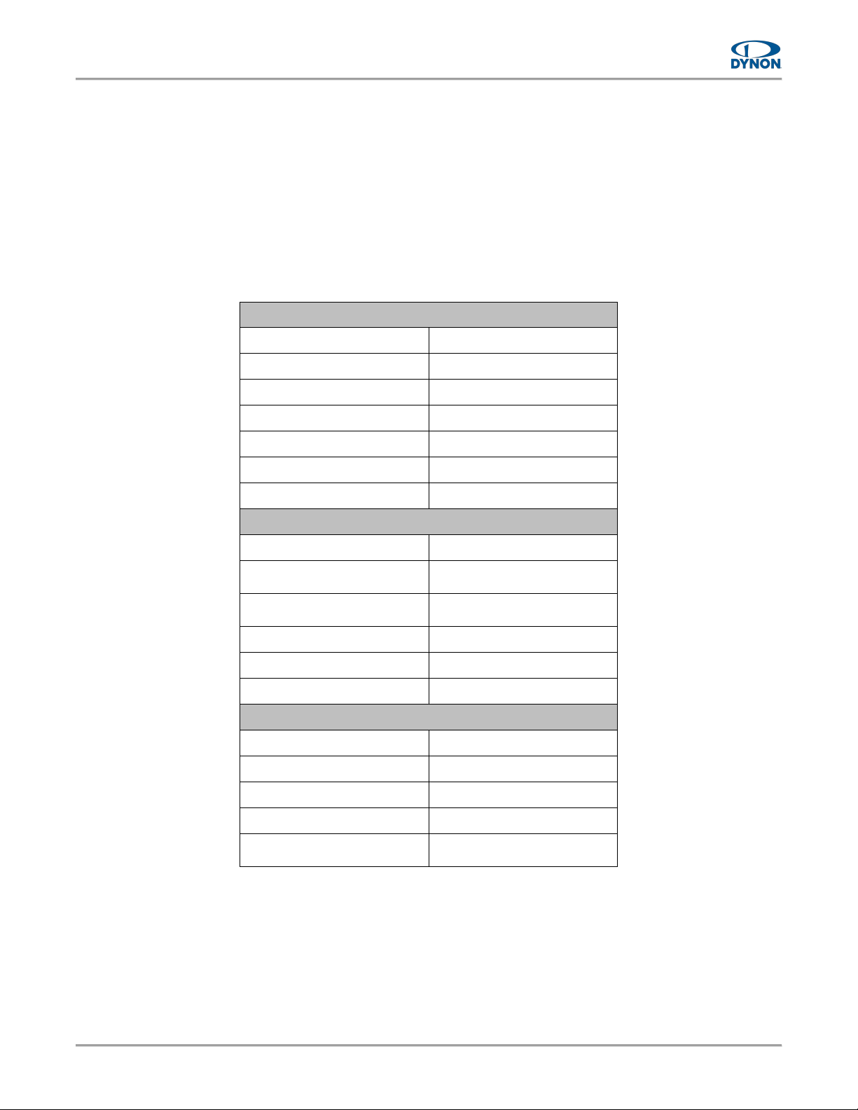
2.1 Specifications
MECHANICAL SPECIFICATIONS
Width
3.35" (85.1 mm)
Height
3.85" (97.8 mm)
Depth
4.27" (108.5 mm)
Weight
1.1 lbs. w/ Battery
Finish
Black Anodized Aluminum
Operating Temperature
-20 to 70 °C
Storage Temperature
-55 to 80 °C
ELECTRICAL SPECIFICATIONS
Power Requirement
10–30V
Power Consumption
0.6A at 12V
0.3A at 24V
Power Consumption when
Battery is Charging
1.1A at 12V
0.6A at 24V
Connector Type
D25 Male
USB Port Type
Type-C USB 2.0
USB Port Power Output
(1)
0.5V
DISPLAY SPECIFICATIONS
Display Type
LCD
Resolution
720 x 720 px
Vertical Viewing Angle
80°
Horizontal Viewing Angle
80°
Screen Treatments
Anti-Reflective
Anti-Fingerprint
(1) Charging external devices using the USB port is prohibited.
Page 10
Page | 2-2
D30 - Installation and Maintenance Manual, Rev A, 7/20/2023
2.2 Basic Controls
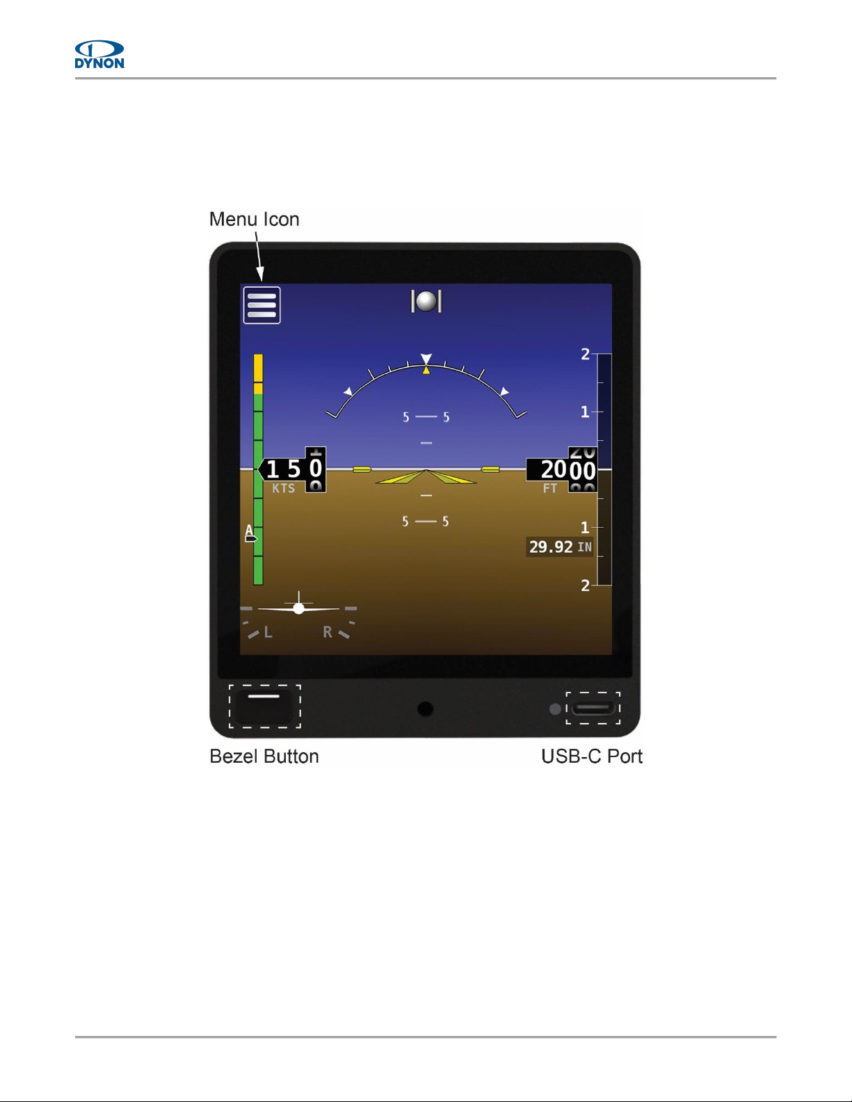
Operating the D30 is intuitive for people familiar with flight instrumentation. Basic operation
happens via touching the actual indicators on the screen or the menu icon in the upper left corner
of screen. The front bezel has an ON/OFF button (i.e., Bezel Button) and a USB-C port.
Figure 1: Dynon D30
Page 11
D30 - Installation and Maintenance Manual, Rev A, 7/20/2023
Page | 2-3
2.3 System Operation
No special operating procedures are required for using the D30. Operating limitations for the
D30 are listed in the D30 Airplane Flight Manual Supplement document at dynon.com/docs.
2.3.1 Flight Indications
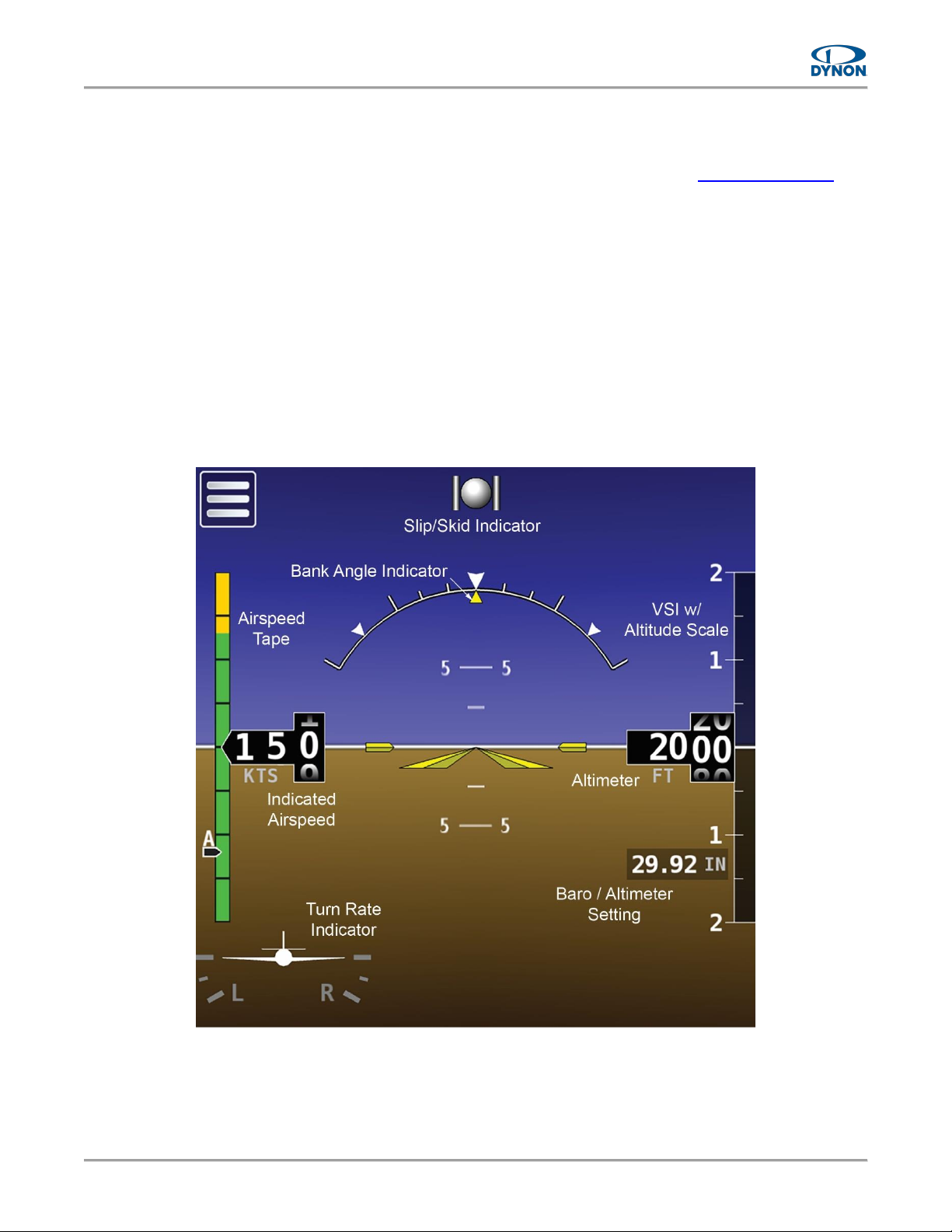
The D30 provides the flight indications listed below. See Figure 2 for locations of the D30's flight
indications
• Airspeed Tape
• Indicated Airspeed
• Slip/Skid Indicator
• Bank Angle Indicator
• Turn Rate Indicator
• Vertical Speed Indicator (VSI) w/
Altitude Scale
• Altimeter
• Barometer / Altimeter Setting
Figure 2: Flight Indications
Page 12

Page | 2-4
D30 - Installation and Maintenance Manual, Rev A, 7/20/2023
2.3.2 Start-up and Shut-down To start-up the D30:
1. Apply power to unit. Unit will start-up.
2. If power is applied and unit does not start-up, then press and hold bezel button for two
seconds. Unit will start-up.
Altitude is not displayed until 30 seconds after start-up. If the D30 senses an
airspeed or altimeter setting adjustment, then altitude is immediately displayed.
To shut-down the D30:
1. Remove power from unit. The SHUTTING DOWN window is displayed with a 30-second
countdown timer. After countdown, unit will shut-down.
2. Alternatively, press and hold bezel button for two seconds. The SHUTTING DOWN
window is displayed with a 3-second countdown timer. After countdown, unit will shutdown.
2.3.3 Screen Brightness Control To adjust the screen brightness on the D30:
1. Touch Menu icon (see Figure 2). Main Menu is displayed.
2. Use Brightness slider bar on Main Menu to set screen brightness level.
3. When done, tap 'arrow' icon to close Main Menu.
2.3.4 Altimeter Setting To change the altimeter setting on the D30:
1. Touch Barometer / Altimeter Setting indicator (see Figure 2). The Altimeter Setting tool
appears.
2. Use the slider bar or tap + / – to adjust the altimeter.
3. When done, touch any other part of screen to hide the Altimeter Setting tool and restore
Altimeter and Altitude Tape.
Page 13
D30 - Installation and Maintenance Manual, Rev A, 7/20/2023
Page | 3-1
3 Installation
This section provides information and instructions for installing the Dynon D30.
3.1 Backup Battery Installation
Per shipping regulations, the D30 is shipped without the backup battery installed. Prior to unit
installation, the D30 needs its backup battery installed.
To install the D30's backup battery:
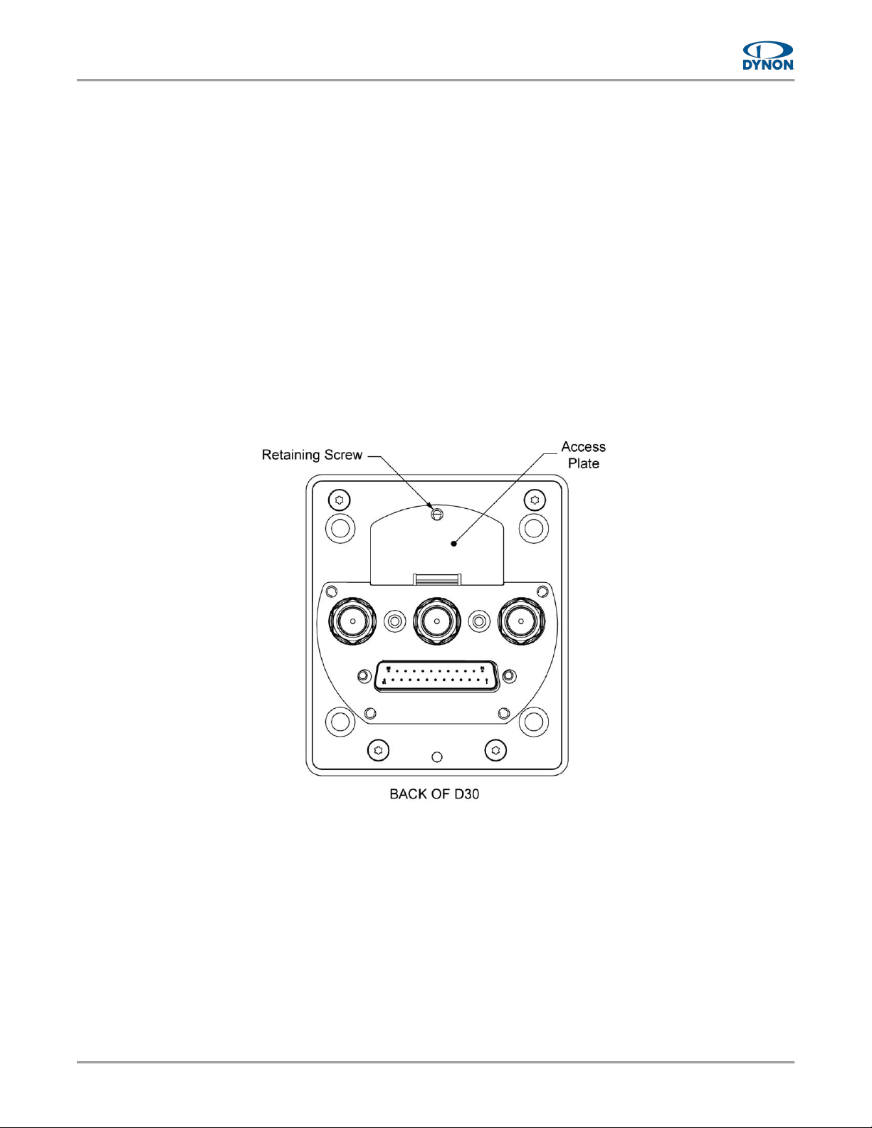
1. On back of unit, loosen captured retaining screw on access plate (see Figure 3), and then
remove access plate.
2. Connect backup battery to unit. Unit and backup battery have mating Molex connectors.
3. Gently insert backup battery and wires into unit.
4. Reposition access plate, and secure with retaining screw.
Figure 3: Backup Battery Access
Page 14

Page | 3-2
D30 - Installation and Maintenance Manual, Rev A, 7/20/2023
3.2 Unit Installation
The D30 should be installed within the primary maximum field-of-view boundary, as close as
practicable to the equipment that displays Primary Flight Information (PFI). According to AC
23.1311-1C, the primary maximum field-of-view is based on vertical and horizontal visual fields
from the pilot's eye reference point that can be observed with eye movement and minimal head
movement only.
The D30 is designed to mount to the instrument panel in a standard 3-1/8"
diameter instrument hole with little modification. See installation guidelines and
specifications below for more information.
The D30 is designed as near direct-fit replacement for the Dynon EFIS-D10A.
Observe the following guidelines and specifications when installing a D30:
• Unit should be installed so its bezel is level across aircraft's lateral axis.
• Wire harness extends about 3" from the rear of the unit. (This can be reduced if 90°
connector shell is used on the wire harness.)
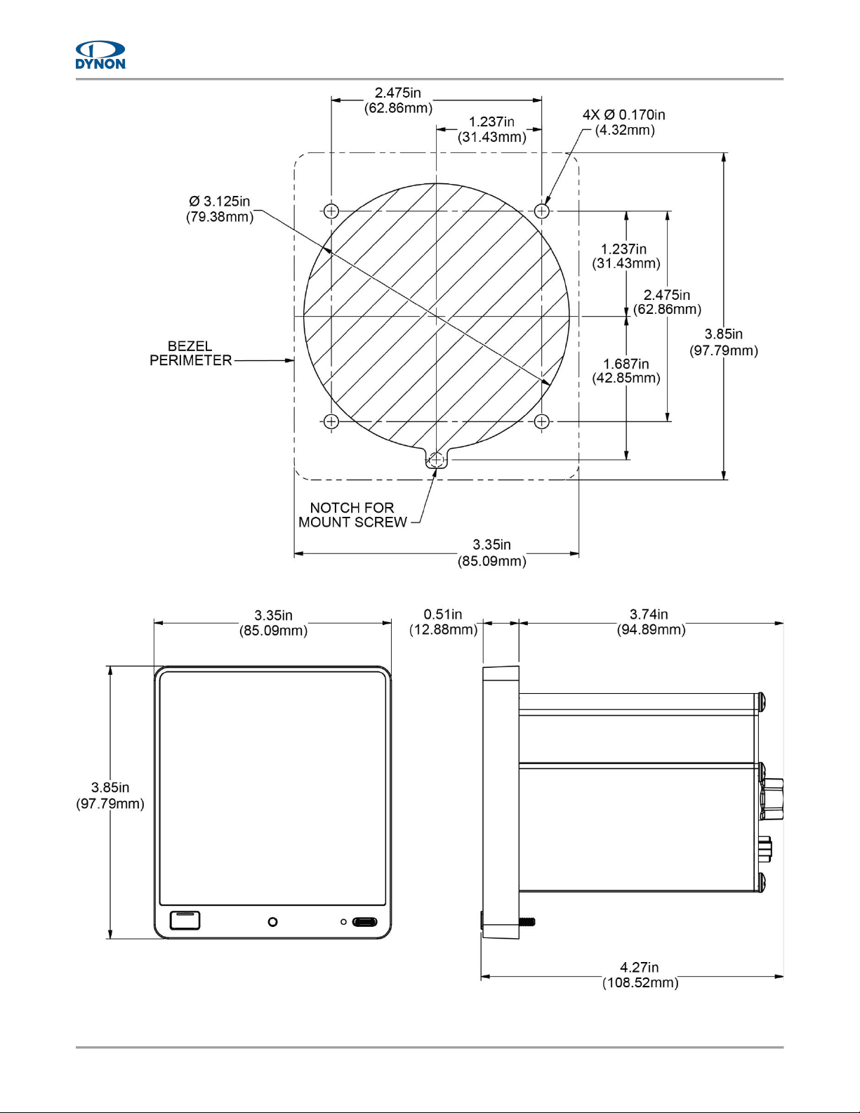
• A small relief must be cut at the bottom of the 3-1/8" instrument panel hole (see Figure
5).
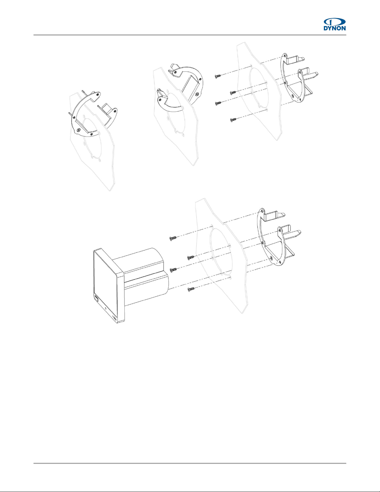
• If retrofitting an EFIS-D10A with a D30, the holes drilled in the instrument panel for the
EFIS-D10A can be reused for the D30's bracket (see Figure 6).
• Front bezel will extend 0.5" beyond the face of the instrument panel.
• Unit will need to be accessed during service; therefore, provide enough slack in the wire
harness and the pitot and static lines to remove the unit from the instrument panel without
disconnection.
• Avoid placing the unit near sources of heat.
Page 15
D30 - Installation and Maintenance Manual, Rev A, 7/20/2023
Page | 3-3
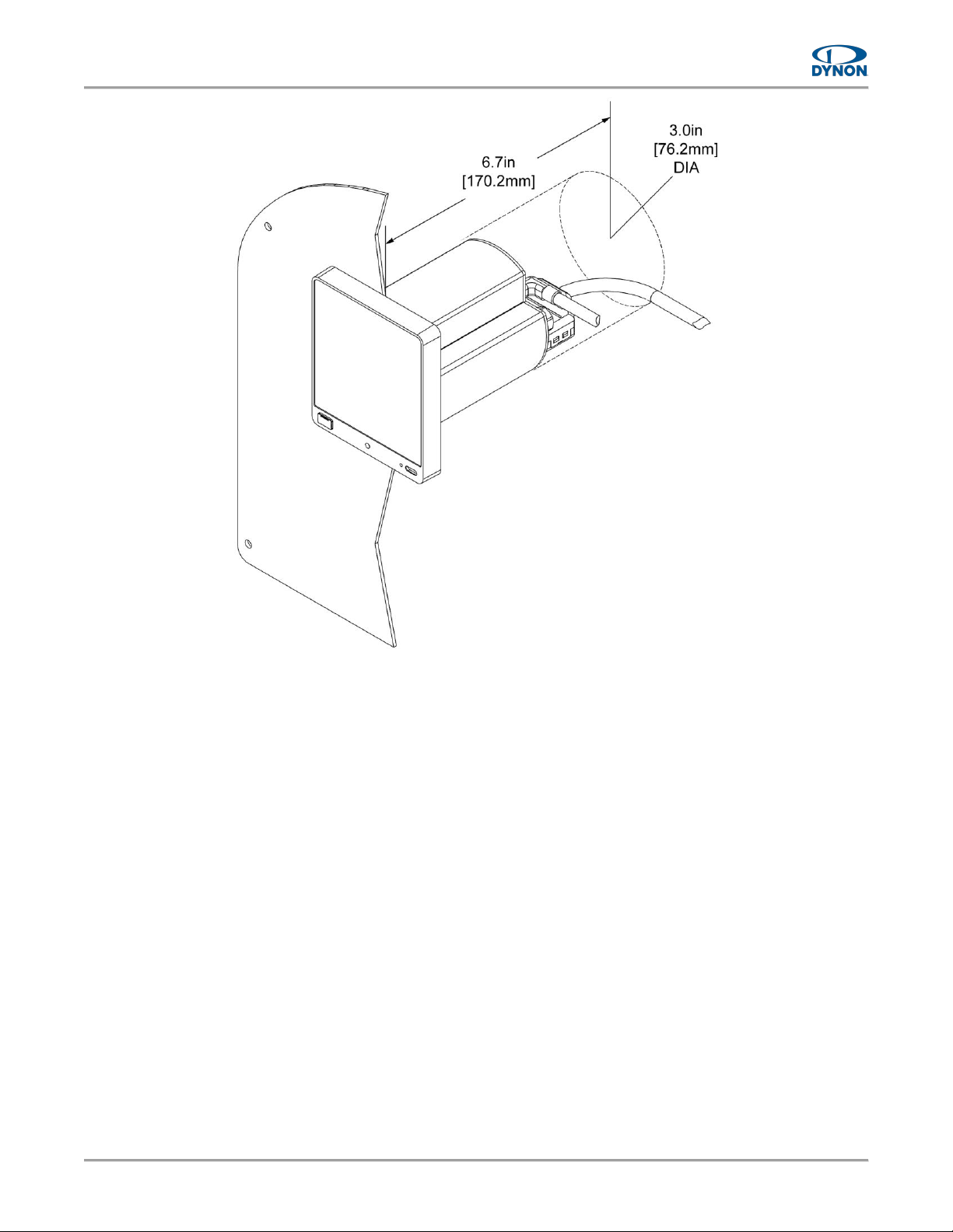
Figure 4: Volume Requirements
To mount the D30 to an instrument panel:
1. If needed, use Figure 5 as a guide to mark and drill holes in instrument panel for mount
bracket attachment.
2. Cut small relief at bottom of instrument hole (see Figure 5) to allow clearance for unit's
retaining screw.
3. Deburr cut edges.
4. Feed mount bracket through instrument hole, as shown in Figure 6, and then secure
to instrument panel with provided hardware.
5. Complete pitot and static connection (see Section 3.3) and electrical installation (see
Section 3.4).
6. Insert unit into instrument hole and mount bracket, as shown in Figure 6.
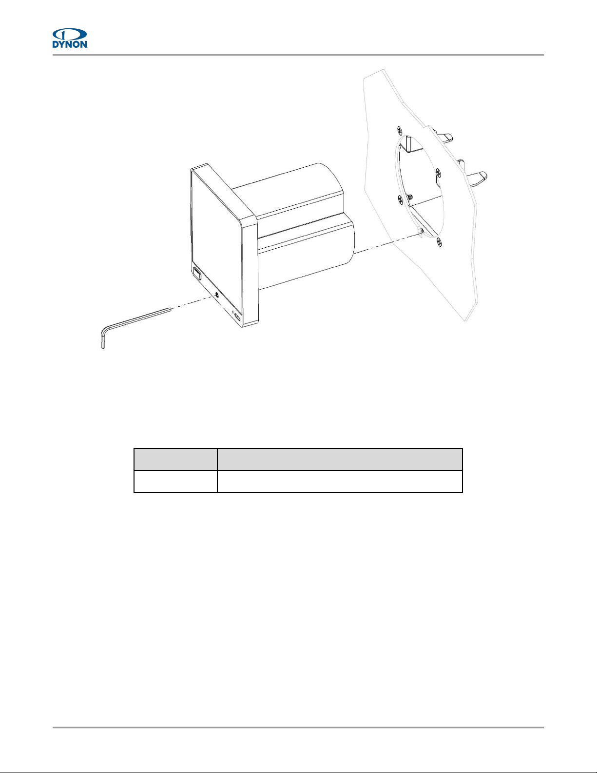
7. Use 3/32" hex wrench to tighten captured retaining screw that secures unit to mount
bracket (see Figure 7). Tighten retaining screw to 3-5 lbs.
Page 16
Page | 3-4
D30 - Installation and Maintenance Manual, Rev A, 7/20/2023
Figure 5: Mounting Dimensions
Page 17
D30 - Installation and Maintenance Manual, Rev A, 7/20/2023
Page | 3-5
Figure 6: Instrument Panel Installation
Page 18
Page | 3-6
D30 - Installation and Maintenance Manual, Rev A, 7/20/2023
Figure 7: Instrument Panel Attachment
3.2.1 Replacement Hardware
If the provided mounting hardware is lost or damage, replace with the hardware is listed below.
Table 1: Replacement Hardware
DYNON P/N
HARDWARE DESCRITION
100980-001
PHIL SCREW 100 DEG, #6-32, 3/8" L, STAINLESS
Page 19

D30 - Installation and Maintenance Manual, Rev A, 7/20/2023
Page | 3-7
3.3 Pitot and Static Connection
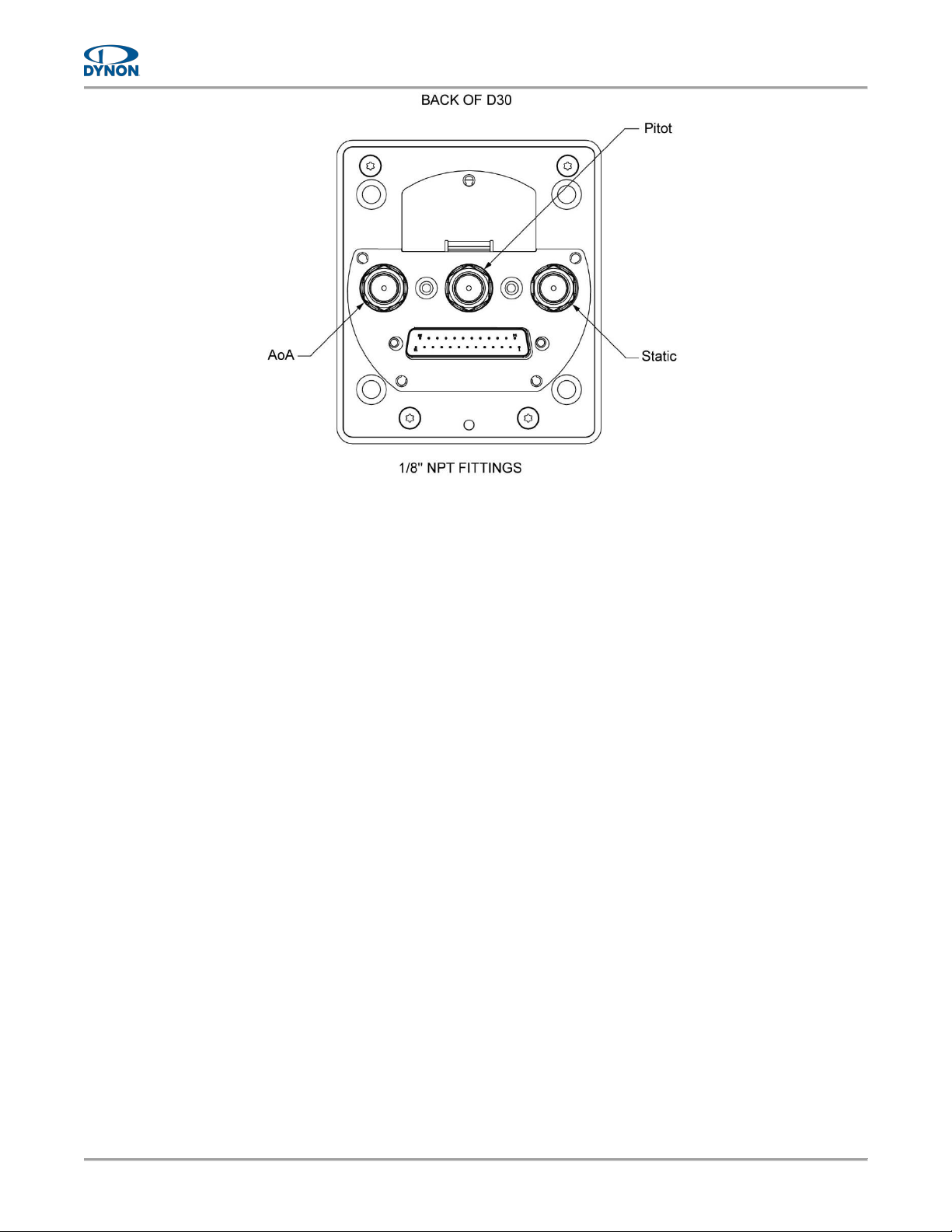
The pitot and static ports on the back of the D30 are equipped with 1/8" NPT female fittings.
Installers need to source appropriate flexible hose and AN/MS fittings for connection to existing
pneumatic tubes/hoses.
To plumb the D30 into the pitot and static systems:
1. Find an appropriate place to connect the D30 plumbing to the airplane's existing pitot and
static systems.
2. Measure and cut correct lengths of flexible hoses to connect to the airplane's pitot and
static systems.
3. Install AN/MS fittings into ends of flexible hoses for connection to the airplane's pitot and
static systems.
4. Route flexible hoses and connect them to the airplane's pitot and static systems using
AN/MS fittings.
Ensure there are no low spots in the flexible hoses that could trap
condensation and cause an obstruction.
5. On a bench, remove plugs from the 1/8" NPT fittings on back of unit (see Figure 8). Leave
the AoA pipe fitting capped.
6. Apply appropriate thread sealant to AN/MS fittings and hand-thread them into the 1/8"
NPT fittings on back of unit.
7. When AN/MS fittings are snug, place a wrench on the unit's 1/8" NPT fittings to prevent
them from rotating, and then carefully tighten.
DO NOT overtighten! If the unit's 1/8" NPT fittings rotate during tightening
it may damage its internal components.
8. Connect flexible tubes to the corresponding AN/MS fittings on back of unit.
Page 20
Page | 3-8
D30 - Installation and Maintenance Manual, Rev A, 7/20/2023
Figure 8: Threaded Pipe Fitting Ports
Page 21
D30 - Installation and Maintenance Manual, Rev A, 7/20/2023
Page | 3-9
3.4 Electrical Installation
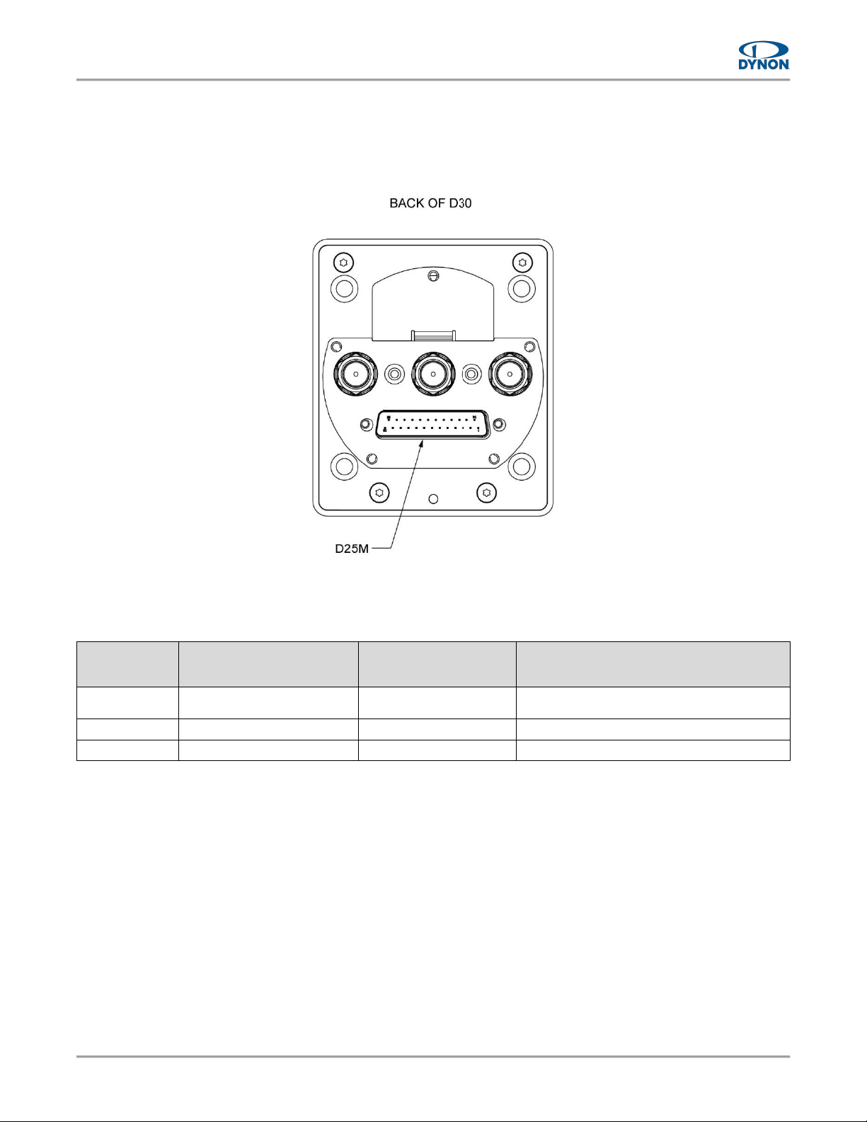
A separate D25 female wire harness (P/N 104749-000) can be purchased from Dynon that plugs
into the D25 male connector on the rear of the D30. The wire harness has designated wires for
connection to airplane power (see Table 2 for pin/wire connections).
Figure 9: D25 Male Connector
Table 2: Pin/Wire Connections
D30
D25 PIN #
D30
D25 WIRE FUNCTION
D30
D25 WIRE COLOR
CONNECTION / NOTES
1
Power
Red
Power Input
3A Circuit Breaker/Fuse
3
Ground
Black
Ground
All Remaining
Do Not Connect
N/A
Do Not Connect
Page 22
Page | 3-10
D30 - Installation and Maintenance Manual, Rev A, 7/20/2023
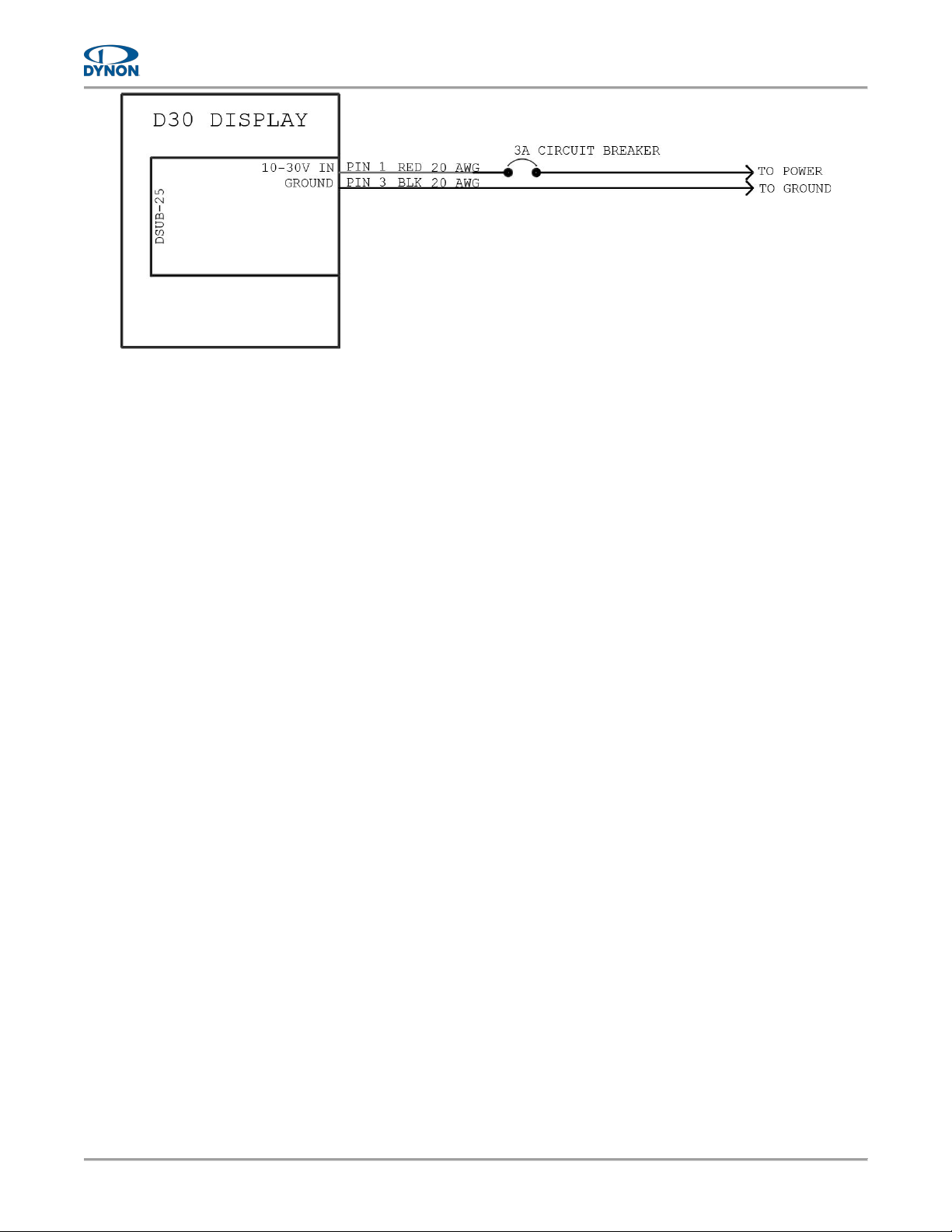
Figure 10: Electrical Connections
3.4.1 Power and Ground Connection
The D30 is compatible with 14V and 28V electrical systems and requires a power supply of 10–
30V DC. Power input to the D30 must be protected with an aviation-grade 3A circuit breaker or
replaceable fuse.
To connect the D30 to an airplane's electrical system:
1. Make sure aircraft power is disconnected.
2. Connect dedicated 3A circuit breaker or replaceable fuse to appropriate electrical bus.
See airplane manufacturer's documentation for guidance.
3. Route Power wire (pin 1) to power source and Ground wire (pin 3) to airframe ground.
4. Support and secure wires to avoid high heat and entanglement with moving
components.
5. Use insulated connectors to connect Power wire to breaker/fuse and Ground wire to
airframe ground.
Page 23

D30 - Installation and Maintenance Manual, Rev A, 7/20/2023
Page | 3-11
3.5 System Check
After the mechanical, electrical, and pneumatic installations, installers need to perform several
checks to verify the physical installation of the D30.
3.5.1 Start-up and Shut-down To start-up and shut-down the D30:
1. Apply power to unit. Unit will start-up.
2. If power is applied and unit does not start-up, press and hold bezel button for 2 seconds.
Unit will start-up. If unit still does not start-up, see Section 4 for help.
3. After start-up, make sure following indicators appear without a Red X covering them:
• Airspeed,
• Altitude (may take up to 30 seconds to appear),
• Attitude,
4. If some indicators are not functional, see Section 4 for troubleshooting.
5. To shut-down unit, press and hold bezel button. The SHUTTING DOWN window is
displayed with a 3-second countdown timer. After countdown, unit will shut-down.
3.5.2 Setup Menu Access To access the D30 Setup Menu:
1. Make sure power is not applied to unit.
2. Push and hold bezel button, and then immediately (within 2 seconds) apply power to unit.
3. Immediately (within 2 seconds) after applying power, release bezel button. The bezel
button will rapidly blink red, and the unit will enter the Setup Menu upon start-up.
Button rapidly blinks red when the unit is entering the Setup Menu upon
start-up; button slowly blinks green when the unit is starting up normally.
3.5.3 Pitot and Static System Leakage
Test the pitot and static systems for leaks (see Section 5.6).
3.5.4 Pitch and Roll Angle
Check, and possibly adjust, the pitch and roll angles on the attitude indicator (see Section 5.8).
3.5.5 Altimeter Function
Per 14 CFR § 91.411, an altimeter system test must be performed by an appropriately rated
person or facility before the airplane can operate under IFR. If testing determines the Altitude
indicator requires adjustment, enter the determined altitude offset in the D30 (see Section 5.9).
Page 24
Page | 3-12
D30 - Installation and Maintenance Manual, Rev A, 7/20/2023
3.6 Configuration
There are several configuration tasks that must be completed to finalize the installation. This
section guides installers through those tasks.
3.6.1 System Configuration
This section details how to configure the D30 per airplane limitations and user preference.
To configure the D30 system settings:
1. Enter Setup Menu (see Section 3.5.2), and then select Settings.
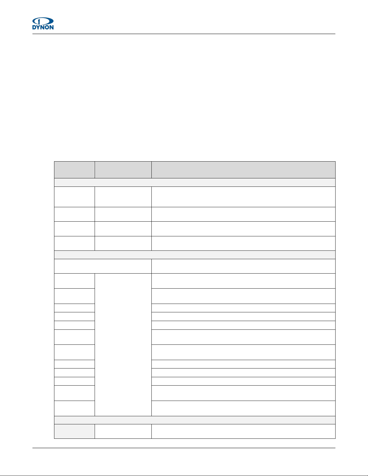
2. Refer to aircraft's POH and configure system settings. See Table 3 for a list of all system
settings.
Table 3: System Settings
SETTING
PARAMETERS
ACTION / NOTES
Units
Speed
Knots
MPH
KPH
Enter preferred unit of measure for displayed speeds.
Altitude
Feet
Meters
Enter preferred unit of measure for displayed altitude.
Pressure
Inches Hg
Millibars
Enter preferred unit of measure for displayed pressures.
Temperature
Celsius
Fahrenheit
Enter preferred unit of measure for displayed temperatures.
Airspeed
Options
Select the v-speeds that apply to the airplane. Selected v-speed are then
listed in menu.
VS0
<numerical value>
Enter airplane's specified stall airspeed with landing gear and flaps
extended.
VS1
Enter airplane's specified stall airspeed with landing gear and flaps
retracted.
VFE
Enter airplane's specified maximum airspeed with flaps extended.
VNO
Enter airplane's specified maximum structural cruising airspeed.
VNE
Enter airplane's specified airspeed to never exceed.
VX
Enter airplane's specified airspeed for maximum altitude gain in shortest
distance.
VY
Enter airplane's specified airspeed for maximum altitude gain in shortest
time.
VA
Enter airplane's specified design maneuvering speed.
VO
Enter airplane's specified maximum operating maneuvering speed.
VG
Enter airplane's specified airspeed for maximum glide.
VMC
Enter airplane's specified minimum airspeed for satisfactory flight with
one engine.
V
YSE
Enter airplane's specified maximum altitude gain in shortest time with
one engine.
Auto Baro
Auto Baro
Toggle Button On/Off
Enables/disables automatic setting of barometer using last indicated
altitude prior to system shutdown after flight.
Page 25

D30 - Installation and Maintenance Manual, Rev A, 7/20/2023
Page | 3-13
3.6.2 Zero-pressure Calibration
Installers need to perform a zero-pressure calibration to calibrate airspeed (see Section 5.7).
Page 26

Page | 3-14
D30 - Installation and Maintenance Manual, Rev A, 7/20/2023
This page intentionally left blank.
Page 27
D30 - Installation and Maintenance Manual, Rev A, 7/20/2023
Page | 4-1
4 Troubleshooting
This section provides information and procedures for troubleshooting issues with the Dynon D30.
4.1 Self-Diagnostics
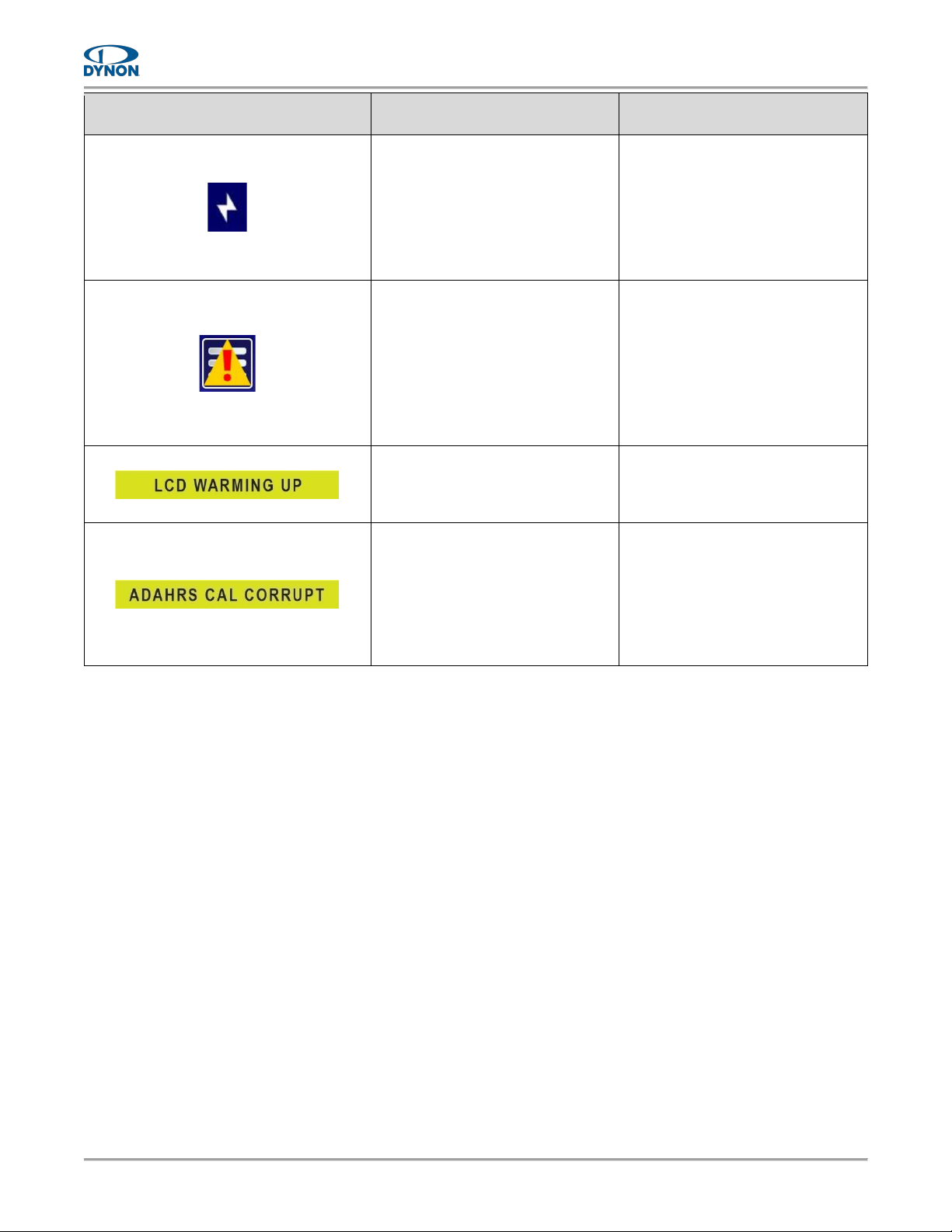
The D30 includes limited self-diagnostic capability. If a fault or other condition is detected, an
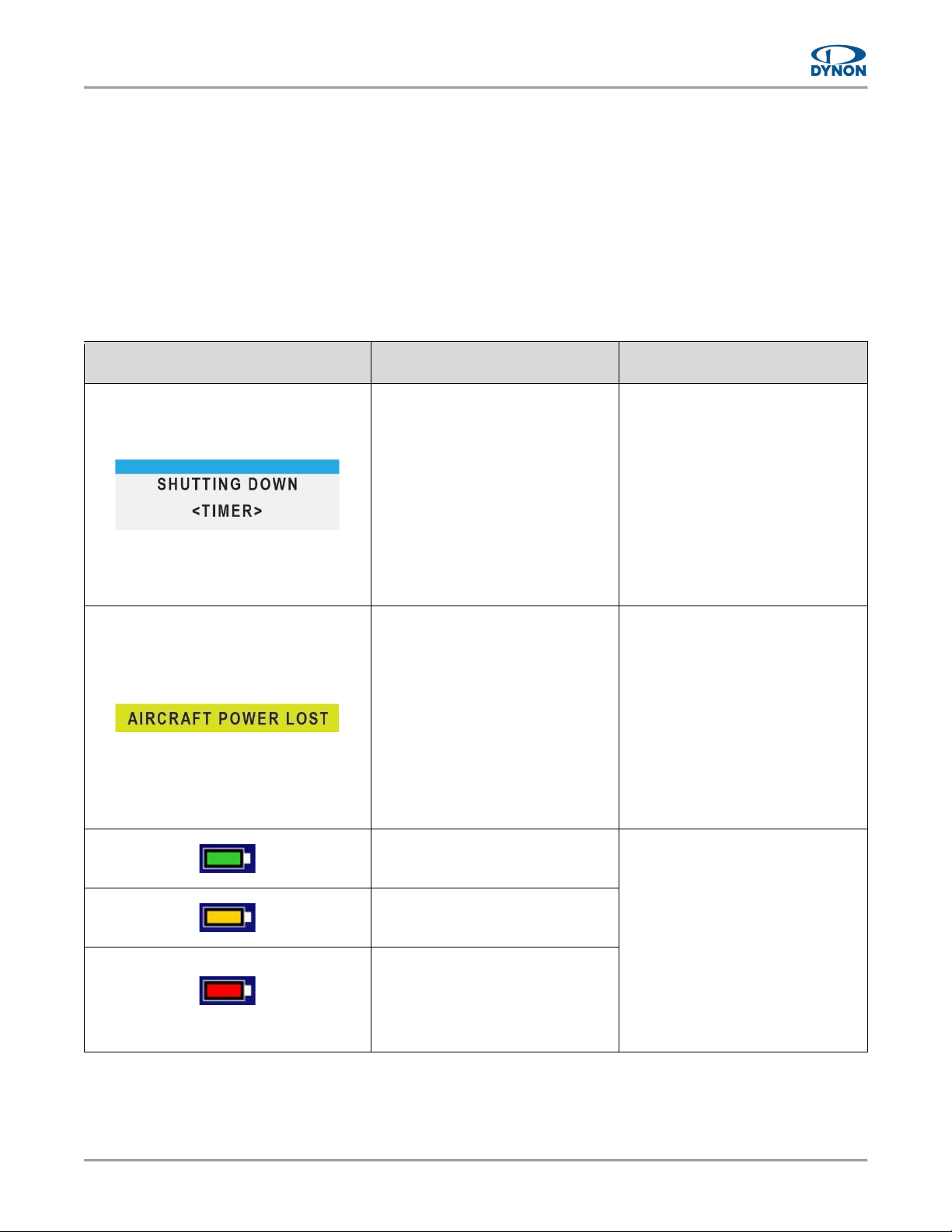
alert is displayed on the screen. Table 4 provides a possible cause and recommended action for
each alert.
Table 4: D30 Alerts
ALERT
CAUSE
RECOMMENDED ACTION
Electrical power has been
removed while the airplane is on
the ground.
If power was not intentionally
turned OFF, inspect/verify the
following:
• Harness connector and mating
connections.
• Power connection at circuit
breaker and power supply bus.
• Power is provided to the
electrical bus.
If condition persists, contact
Dynon Technical Support.
Electrical power has been
removed while the airplane is in
the air.
Land at nearest suitable airport!
Inspect/verify the following:
• Harness connector and mating
connections.
• Power connection at circuit
breaker and power supply bus.
• Power is provided to the
electrical bus.
If condition persists, contact
Dynon Technical Support.
D30 is running on backup battery
power. More than 30 minutes of
battery life remains.
If power was not intentionally
turned OFF, inspect/verify the
following:
• Harness connector and mating
connections.
• Power connection at circuit
breaker and power supply bus.
• Power is provided to the
electrical bus.
If condition persists, contact
Dynon Technical Support.
D30 is running on backup battery
power. Less than 30 minutes of
battery life remains.
(Flashing)
D30 is running on backup battery
power and the battery capacity is
critical. Device shutdown
imminent.
Page 28
Page | 4-2
D30 - Installation and Maintenance Manual, Rev A, 7/20/2023
ALERT
CAUSE
RECOMMENDED ACTION
The D30 is not detecting the
backup battery.
If backup battery was not
intentionally removed, inspect
battery connector and mating
connections.
If condition persists, contact
Dynon Technical Support.
The D30 has detected an issue in
its software.
This message is not an
emergency, nor does it make the
D30 unairworthy.
This issue must be corrected
before the next flight.
Follow on-screen instructions to
report issue to Dynon Technical
Support.
The D30 has detected low internal
temperatures during startup and
has turned on an internal heater
to warm up the LCD screen.
Normal operations may resume
after the alert is removed.
The D30 has detected an internal
issue in its firmware or calibration
tables.
This issue must be corrected
before the next flight.
Contact Dynon Technical Support.
4.2 Unit Does Not Start-up
If unit does not start-up, thoroughly check electrical connections, and retry. If unit still does not
start-up, contact Dynon Technical Support.
4.3 Airspeed Incorrect
If the airspeed indicator appears incorrect, the airspeed function may need to be re-calibrated.
Perform a zero-pressure calibration (see Section 5.7).
4.4 Airspeed Indicator Frozen or Indicates Zero
If the airspeed indicator is a fixed value of zero, and does not change, or only increases slightly,
the pitot sensor and lines may be disconnected or leaking.
• Inspect pitot system for loose or open connections and reconnect and tighten as needed.
If the airspeed indicator is a fixed value that does not change, the pitot sensor and lines may be
obstructed. The following must be performed by an appropriately rated person or facility.
• Disconnect the pitot and static systems from all sensing instruments and reverse flush
the system with compressed air. Failure to disconnect all sensing instruments will result
in instrument damage.
Page 29

D30 - Installation and Maintenance Manual, Rev A, 7/20/2023
Page | 4-3
4.5 Altitude Indicator Frozen
If the altitude indicator is a fixed value that does not change, the static sensor and lines may be
obstructed. The following must be performed by an appropriately rated person or facility.
• Disconnect the static system from all sensing instruments and reverse flush the system
with compressed air. Failure to disconnect all sensing instruments will result in instrument
damage.
Page 30

Page | 4-4
D30 - Installation and Maintenance Manual, Rev A, 7/20/2023
This page intentionally left blank.
Page 31
D30 - Installation and Maintenance Manual, Rev A, 7/20/2023
Page | 5-1
5 Maintenance
This section provides information and procedures for maintaining the Dynon D30.
5.1 Periodic Maintenance
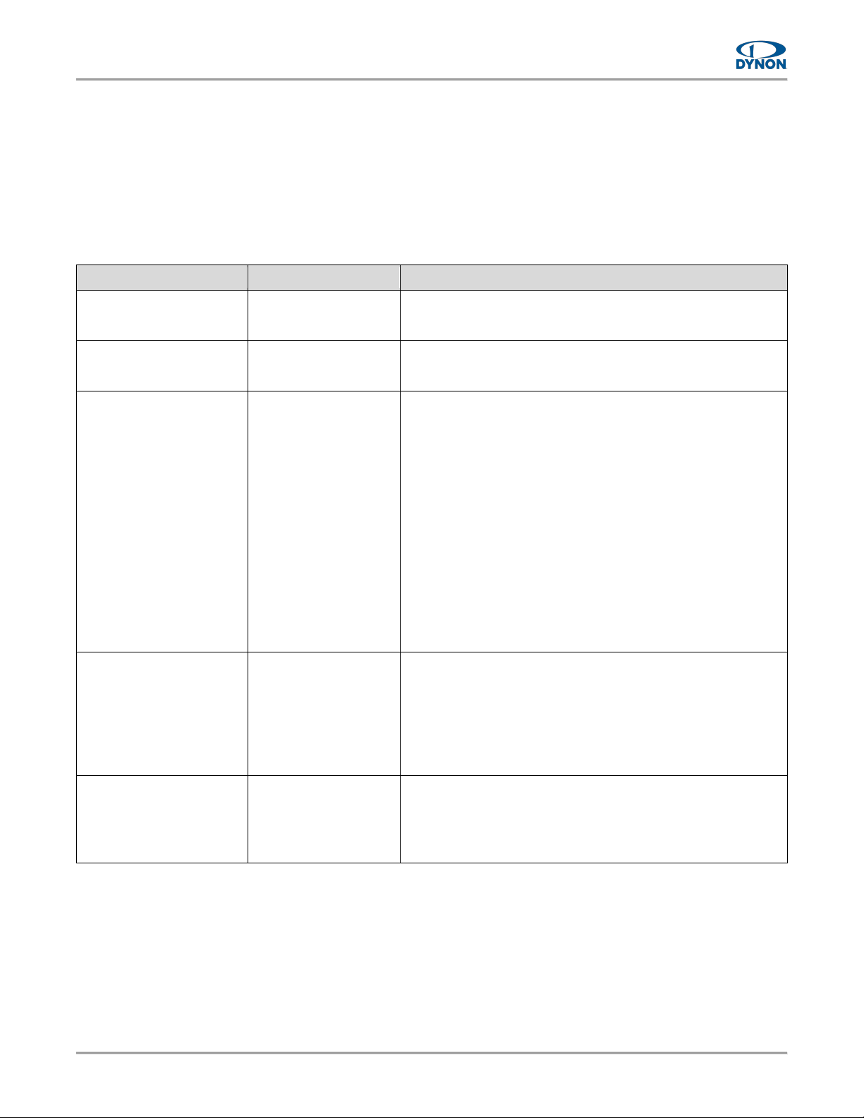
See Table 5 for maintenance tasks that must be performed routinely.
Table 5: Periodic Maintenance
TASK
FREQUENCY
DESCRIPTION / PROCEDURE
Backup Battery Test
Once Every 12
Calendar Months
See Section 5.3.
Zero-pressure Calibration
Once Every 12
Calendar Months
See Section 5.7.
Visual Inspection
Once Every 12
Calendar Months
The D30 needs to be routinely inspected to ensure the
continued integrity of the installation:
• Inspect unit for secure attachment to mount bracket;
inspect mount bracket for secure attachment to
instrument panel.
• Inspect unit for signs of corrosion.
• Inspect condition of wiring, shield terminals, routing,
attachment/clamping, and any airframe penetration
points.
• Inspect display screen, bezel, and buttons for dust, dirt,
or obstructions. Clean as needed (see Section 5.2).
• Inspect backup battery for corrosion or damage. Replace
if needed (see Section 5.4).
Display Backlighting
Once Every 24
Calendar Months
Display brightness may dim over time and not perform as
well in direct sunlight.
The user must determine by observation when the display
brightness is not suitable for intended use.
If determined unsuitable, contact Dynon Technical Support.
Altimeter
For IFR Operations,
every 24 calendar
months in accordance
with §91.411
Test the Altimeter system per Title 14 CFR Part 43,
Appendix E and document in accordance with §43.9 (see
Section 5.9).
Page 32

Page | 5-2
D30 - Installation and Maintenance Manual, Rev A, 7/20/2023
5.2 Cleaning
The D30 screen and bezel can be cleaned with any cloth intended for LCD screens, as well as
soft cotton cloth dampened with clean water. Avoid using harsh cleaning agents. Take care to
not scratch surface of display.
5.3 Backup Battery Test
The following procedure will determine if the internal backup battery meets the 45-minute
expected operation duration.
The backup battery needs to be fully charged prior to beginning the test. If
backup battery was recently used for more than 5 minutes, allow it to charge
on airplane power for at least 4 hours before performing test.
To check the D30 backup battery:
1. Set D30 screen to full brightness (see Section 2.3.3).
2. Remove airplane power from unit. When power is lost, a 30-second countdown window
will appear.
3. Touch SHUTTING DOWN countdown timer to allow unit to operate on battery power.
Battery icon will appear in upper right corner of screen.
4. Allow unit to operate for 45 minutes.
5. If battery icon does not turn red during that time, then battery passed test.
6. If battery icon does turn red during that time, then battery failed test and needs to be
replaced (see Section 5.4).
7. Before returning to service, restore airplane power to unit and allow battery to charge for
4 hours.
Page 33

D30 - Installation and Maintenance Manual, Rev A, 7/20/2023
Page | 5-3
5.4 Backup Battery Replacement
This section provides replacement procedures for the D30 backup battery.
If backup battery replacement requires the unit to be disconnected from the
electrical and/or pitot and static systems, it must be performed by an appropriately
rated person or facility.
Replacement D30 backup batteries (P/N 104243-000) are available from Dynon
or authorized dealers and can be replaced in the field.
To replace the D30 backup battery:
1. Make sure airplane power is disconnected.
2. Use 3/32" hex wrench to loosen retaining screw that secures unit to mount bracket (see
Figure 11).
3. Carefully slide unit out.
4. On back of unit, loosen captured retaining screw on access plate (see Figure 12), and
then remove access plate.
5. Gently pull battery wires to remove old battery.
6. Disconnect old backup battery from unit and connect new backup battery to unit. Unit
and backup battery have mating Molex connectors.
7. Gently insert new backup battery and wires into unit.
8. Reposition access plate, and secure with retaining screw.
9. Carefully slide unit into instrument panel.
10. Use 3/32" hex wrench to tighten retaining screw that secures unit to mount bracket (see
Figure 11). Tighten retaining screw to 3-5 lbs.
11. Before returning to service, restore power to unit and allow new battery to charge for 4
hours.
Page 34

Page | 5-4
D30 - Installation and Maintenance Manual, Rev A, 7/20/2023
Figure 11: Unit Removal and Re-installation
Figure 12: Backup Battery Access
Page 35

D30 - Installation and Maintenance Manual, Rev A, 7/20/2023
Page | 5-5
5.5 Unit Removal and Replacement
This section provides procedures for removing and replacing the D30.
The following procedure must be performed by an appropriately rated person or
facility.
To remove the D30:
1. Make sure airplane power is disconnected.
2. Use 3/32" hex wrench to loosen retaining screw that secures unit to mount bracket (see
Figure 11).
3. Carefully slide unit out.
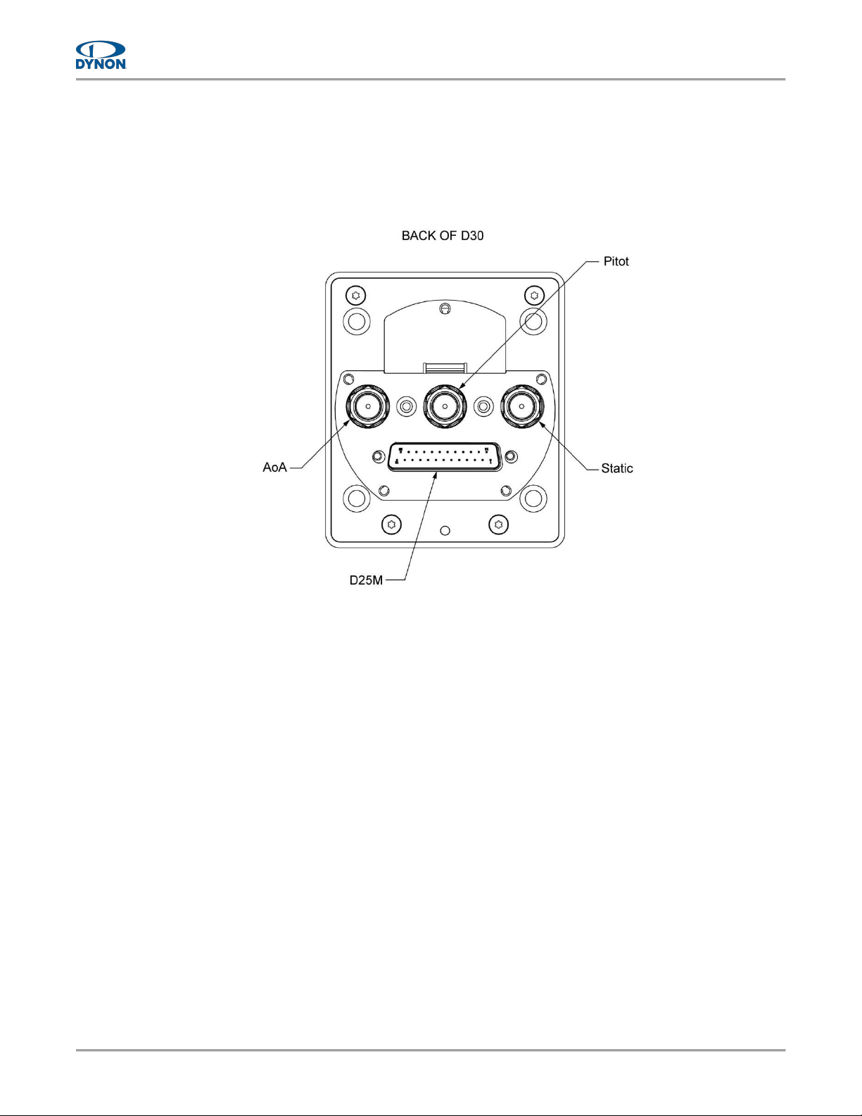
4. Disconnect harness connector from back of unit (see Figure 13) by loosening retaining
screws and pulling out connector.
5. Disconnect and plug pitot and static flexible tubes from back of unit (see Figure 13). Mark
tubes for identification during re-installation.
6. Use a wrench to loosen and remove AN/MS fittings from 1/8" NPT fittings on back of unit.
Retain AN/MS fittings for re-installation.
7. Cap open 1/8" NPT fittings.
To install the D30:
1. Remove caps from 1/8" NPT fittings on back of unit (see Figure 13). Leave AoA pipe
fitting capped.
2. Apply appropriate thread sealant to AN/MS fittings and hand-thread them into the 1/8"
NPT fittings on back of unit.
3. When AN/MS fittings are snug, place a wrench on the unit's 1/8" NPT fittings to prevent
them from rotating, and then carefully tighten.
DO NOT overtighten! If the unit's 1/8" NPT fittings rotate during tightening
it may damage its internal components.
4. Unplug and connect flexible tubes to the corresponding AN/MS fittings on back of unit.
5. Plug harness connector into mating connector on back of unit (see Figure 13), and then
hand-tighten retention screws to secure.
6. Carefully slide unit into instrument panel.
7. Use 3/32" hex wrench to tighten retaining screw that secures unit to mount bracket (see
Figure 11). Tighten retaining screw to 3-5 lbs.
Page 36
Page | 5-6
D30 - Installation and Maintenance Manual, Rev A, 7/20/2023
8. If replacing original unit:
A. Apply power to unit. If unit does not start-up, see Section 4 for troubleshooting.
B. Perform pitot and static leakage tests (see Section 5.6).
9. If replacing with new unit, perform all system check procedures (see Section 3.5) and
configuration procedures (see Section 3.6).
Figure 13: Pneumatic Pipe Fittings and D25M Connector
Page 37

D30 - Installation and Maintenance Manual, Rev A, 7/20/2023
Page | 5-7
5.6 Pitot and Static Leakage Tests
These are performed to make sure there are no leaks in the pitot or static lines. The tests need
to be performed during initial installation and then anytime the pitot and static tubes are removed
from the D30.
When performing the leakage tests, put the D30 into Pitot Static Test Mode. Not
doing so can corrupt the D30’s internal calibrations.
To perform pitot/static system tests:
1. Enter Setup Menu (see Section 3.5.2), and then select Calibration > Pit./Stat. Test.
2. Touch Enable. The Pitot Static Test Mode notification bar appears on screen.
3. Perform pitot and static leakage tests per Title 14 CFR Part 43, Appendix E.
4. Service systems as needed.
5. Disable Pitot Static Test Mode:
• Touch Pitot Static Test Mode notification bar on screen, or,
• Touch Main Menu icon, select Setup Menu > Calibration > Pit./Stat. Test, and then
touch Disable.
Page 38

Page | 5-8
D30 - Installation and Maintenance Manual, Rev A, 7/20/2023
5.7 Zero-pressure Calibration
This calibration samples pitot and static pressures. This calibration needs to be performed during
initial setup to calibrate airspeed, and as needed if airspeed indicator appears incorrect.
This calibration should be performed in a windless environment to provide the best possible
Indicated Airspeed (IAS) readings at very low airspeeds.
To perform zero pressure calibration:
1. Enter Setup Menu (see Section 3.5.2), and then select Calibration.> Zero Press Cal.
2. Touch Acquire, and then follow on-screen instructions.
5.8 Pitch/Roll Angle Check & Adjustment
This section provides instructions for checking and adjusting the pitch and roll angles on the
attitude indicator to compensate for a tilted instrument panel or unlevel installation. This
calibration should be considered a configuration step that does not need to be performed
routinely.
Pitch angle calibration is not the same as a parallax adjustment on a mechanical attitude
indicator. Additionally, this calibration should not be used to "zero-out" pitch when the airplane
is at an attitude other than level.
Pitch angle can be adjusted 30° to compensate for tilted instrument panels;
roll angle can be adjusted 6°.
To check and adjust the pitch and roll angles:
1. Level airplane according to manufacturer's instructions.
2. View attitude indicator on screen.
• If attitude indicator is aligned with horizon indicator, no further action is required.
• If attitude indicator is not aligned with horizon indicator, complete remaining steps.
3. Enter Setup Menu (see Section 3.5.2), and then select Calibration > Pitch/Roll.
4. Tap up/down arrows to increase or decrease angle as needed to correct pitch on attitude
indicator.
5. Tap left/right arrows to increase or decrease angle as needed to correct roll on the Attitude
indicator.
6. Press ACCEPT.
Page 39

D30 - Installation and Maintenance Manual, Rev A, 7/20/2023
Page | 5-9
5.9 Altimeter Function Testing & Altitude Offset
The D30’s altimeter function must be tested in accordance with 14 CFR, Part 43, Appendix E by
an appropriately rated person or facility.
When performing the Altimeter Function Test, put the D30 into Pitot Static Test
Mode. Not doing so can corrupt the D30’s internal calibrations.
To perform the altimeter function test:
1. Enter Setup Menu (see Section 3.5.2), and then select Calibration > Pit./Stat. Test.
2. Touch Enable. The Pitot Static Test Mode notification bar appears on screen.
3. Perform altimeter function tests per Title 14 CFR Part 43, Appendix E.
4. Determine offset value.
5. Disable Pitot Static Test Mode:
• Touch Pitot Static Test Mode notification bar on screen, or,
• Touch Main Menu icon, select Setup Menu > Calibration > Pit./Stat. Test, and then
touch Disable.
To enter an altitude offset:
1. Make sure altimeter setting is correct (see Section 2.3.4 for instructions).
2. Enter Setup Menu (see Section 3.5.2), and then select Calibration > Altitude Offset.
3. Enter the offset value as determined by testing.
4. Press OK.
Page 40

Page | 5-10
D30 - Installation and Maintenance Manual, Rev A, 7/20/2023
5.10 System Software Updates
Occasionally, Dynon will release new system software for the D30. When this occurs, Dynon will
send notification to registered owners.
To download system software:
1. Navigate to Dynon’s software download website: dynon.com/download.
2. Download latest software file (.dyn) to a USB drive. The file must be on root directory of
USB drive or will not be recognizable by the D30.
To update system software:
1. While D30 is OFF, use a USB-C adapter to insert USB drive into USB-C port on D30
bezel.
2. Turn D30 ON and wait, and then follow on-screen instructions.
3. When finished, remove USB drive and adapter from USB-C port.
Leaving a USB drive and/or adapter in the USB-C port or using the USB-C
port to charge electronic devices is prohibited.
 Loading...