


 Loading...
©2002-2006 Dynojet Research, Inc. All Rights Reserved.
WinPEP 7 User Guide
This manual is copyrighted by Dynojet Research, Inc., hereafter referred to as Dynojet, and all rights are reserved. This manual, as well as the software described in it, is furnished under license and may only be used or copied in accordance with the terms of such license. This manual is furnished for informational use only, is subject to change without notice, and should not be construed as a commitment by Dynojet. Dynojet assumes no responsibility or liability for any error or inaccuracies that may appear in this manual. Except as permitted by such license, no part of this manual may be reproduced, stored in a retrieval system, or transmitted, in any form or by any means, electronic, mechanical, recording, or otherwise, without the prior written permission of Dynojet.
The Dynojet logo is a trademark of Dynojet Research, Inc.
Any trademarks, trade names, service marks, or service names owned or registered by any other company and used in this guide are the property of their respective companies.
Dynojet Research, Inc., 2191 Mendenhall Drive, North Las Vegas, Nevada 89081, USA.
Printed in USA.
Part Number: 98118103 Version 02 (08/2006)

TABLE OF CONTENTS
Chapter 1 Specifications and Installation
Conventions Used In This Manual . . . . . . . . . . . . . . . . . . . . . . . . . . . . . . . 1-2
Technical Support . . . . . . . . . . . . . . . . . . . . . . . . . . . . . . . . . . . . . . . . . . . 1-2
Computer Specifications . . . . . . . . . . . . . . . . . . . . . . . . . . . . . . . . . . . . . . 1-3
License Agreement . . . . . . . . . . . . . . . . . . . . . . . . . . . . . . . . . . . . . . . . . . 1-3
Registration . . . . . . . . . . . . . . . . . . . . . . . . . . . . . . . . . . . . . . . . . . . . . . . .1-3
Custom Installation . . . . . . . . . . . . . . . . . . . . . . . . . . . . . . . . . . . . . . . . . . 1-8
Compact Installation . . . . . . . . . . . . . . . . . . . . . . . . . . . . . . . . . . . . . . . . . 1-8
Dynamic Help Files . . . . . . . . . . . . . . . . . . . . . . . . . . . . . . . . . . . . . . . . . . 1-9
Removing or Repairing an Installation . . . . . . . . . . . . . . . . . . . . . . . . . . . 1-10
Chapter 2 Dyno and WinPEP Basics
Hardware and Software . . . . . . . . . . . . . . . . . . . . . . . . . . . . . . . . . . . . . . . 2-2
Theory of Operation . . . . . . . . . . . . . . . . . . . . . . . . . . . . . . . . . . . . . . . . . 2-2
Dyno Electronics Symbols . . . . . . . . . . . . . . . . . . . . . . . . . . . . . . . . . . . . .2-5
The Pendant . . . . . . . . . . . . . . . . . . . . . . . . . . . . . . . . . . . . . . . . . . . . . . . 2-6
WinPEP 7 Menus . . . . . . . . . . . . . . . . . . . . . . . . . . . . . . . . . . . . . . . . . . . . 2-7
Searching the User Manual . . . . . . . . . . . . . . . . . . . . . . . . . . . . . . . . . . . . 2-9
On-Line Manuals for Your Dyno . . . . . . . . . . . . . . . . . . . . . . . . . . . . . . . . 2-10
Using the Tutorials . . . . . . . . . . . . . . . . . . . . . . . . . . . . . . . . . . . . . . . . . . 2-11
Creating a New Folder . . . . . . . . . . . . . . . . . . . . . . . . . . . . . . . . . . . . . . . 2-17
Dyno Run Files . . . . . . . . . . . . . . . . . . . . . . . . . . . . . . . . . . . . . . . . . . . . . 2-18
i
Mulit Chapter Template March 2006

TA B L E O F C O N T E N T S
Chapter 3 Getting Started With WinPEP 7
WinPEP’s Screens . . . . . . . . . . . . . . . . . . . . . . . . . . . . . . . . . . . . . . . . . . . . 3-2
When a Folder is Selected . . . . . . . . . . . . . . . . . . . . . . . . . . . . . . . . . . . . .3-8
Com Port Selection . . . . . . . . . . . . . . . . . . . . . . . . . . . . . . . . . . . . . . . . . 3-10
Connecting the Dyno Electronics . . . . . . . . . . . . . . . . . . . . . . . . . . . . . . . 3-11
Troubleshooting the Dyno Electronics . . . . . . . . . . . . . . . . . . . . . . . . . . . 3-13
Replacing the Fuses in the Dyno Electronics . . . . . . . . . . . . . . . . . . . . . . . 3-13
Loading a Template . . . . . . . . . . . . . . . . . . . . . . . . . . . . . . . . . . . . . . . . 3-16
File Menu . . . . . . . . . . . . . . . . . . . . . . . . . . . . . . . . . . . . . . . . . . . . . . . . 3-17
Search Menu . . . . . . . . . . . . . . . . . . . . . . . . . . . . . . . . . . . . . . . . . . . . . . 3-17
Tools Menu . . . . . . . . . . . . . . . . . . . . . . . . . . . . . . . . . . . . . . . . . . . . . . .3-18
Display Menu . . . . . . . . . . . . . . . . . . . . . . . . . . . . . . . . . . . . . . . . . . . . . 3-19
Help Menu . . . . . . . . . . . . . . . . . . . . . . . . . . . . . . . . . . . . . . . . . . . . . . . 3-20
Chapter 4 Making A Run
Making a Test Run . . . . . . . . . . . . . . . . . . . . . . . . . . . . . . . . . . . . . . . . . . . 4-2
Making a Run . . . . . . . . . . . . . . . . . . . . . . . . . . . . . . . . . . . . . . . . . . . . . . 4-3
Graphing Negative Values . . . . . . . . . . . . . . . . . . . . . . . . . . . . . . . . . . . . . 4-7
Negative Horsepower Test—Drive Train . . . . . . . . . . . . . . . . . . . . . . . . . . . 4-8
Negative Horsepower Test—Different Brands of Oil . . . . . . . . . . . . . . . . . . 4-9
Chapter 5 Graphing A Run
Printing a Graph . . . . . . . . . . . . . . . . . . . . . . . . . . . . . . . . . . . . . . . . . . . . 5-5
Setting Printer Properties . . . . . . . . . . . . . . . . . . . . . . . . . . . . . . . . . . . . . . 5-5
Changing the Text Printed At the Top (or Bottom) of the Graph . . . . . . . . 5-5
Previewing Print Jobs . . . . . . . . . . . . . . . . . . . . . . . . . . . . . . . . . . . . . . . . . 5-6
ii
Mulit Chapter Template March 2006

TA B L E O F C O N T E N T S
Chapter 6 Advanced MakeRun Features
Using Auto Start/Stop . . . . . . . . . . . . . . . . . . . . . . . . . . . . . . . . . . . . . . . . 6-9
Dynojet expansion systems . . . . . . . . . . . . . . . . . . . . . . . . . . . . . . . . . . . 6-11
Supported Systems . . . . . . . . . . . . . . . . . . . . . . . . . . . . . . . . . . . . . . . . . 6-11
Exploring the Gauge Toolbar . . . . . . . . . . . . . . . . . . . . . . . . . . . . . . . . . . 6-13
Adding a Round Gauge . . . . . . . . . . . . . . . . . . . . . . . . . . . . . . . . . . . . . . 6-14
Adding a Multi Bar Gauge . . . . . . . . . . . . . . . . . . . . . . . . . . . . . . . . . . . . 6-16
Loading a Template . . . . . . . . . . . . . . . . . . . . . . . . . . . . . . . . . . . . . . . . . 6-20
Saving a Template . . . . . . . . . . . . . . . . . . . . . . . . . . . . . . . . . . . . . . . . . . 6-20
MakeRun Configuration . . . . . . . . . . . . . . . . . . . . . . . . . . . . . . . . . . . . . . 6-23
PID Coefficients . . . . . . . . . . . . . . . . . . . . . . . . . . . . . . . . . . . . . . . . . . . . 6-23
Torque Cell Calibration . . . . . . . . . . . . . . . . . . . . . . . . . . . . . . . . . . . . . . 6-24
Analog Configuration . . . . . . . . . . . . . . . . . . . . . . . . . . . . . . . . . . . . . . . 6-24
Dyno Electronics Information . . . . . . . . . . . . . . . . . . . . . . . . . . . . . . . . . . 6-25
Edit Mode . . . . . . . . . . . . . . . . . . . . . . . . . . . . . . . . . . . . . . . . . . . . . . . . 6-25
Template Options . . . . . . . . . . . . . . . . . . . . . . . . . . . . . . . . . . . . . . . . . . 6-25
Gauge Configuration . . . . . . . . . . . . . . . . . . . . . . . . . . . . . . . . . . . . . . . . 6-26
Dyno Port . . . . . . . . . . . . . . . . . . . . . . . . . . . . . . . . . . . . . . . . . . . . . . . . 6-26
Chapter 7 Advanced Graph Features
Formatting Graphs Using the ListView Shortcut Menu . . . . . . . . . . . . . . . . 7-2
Change Line Style . . . . . . . . . . . . . . . . . . . . . . . . . . . . . . . . . . . . . . . . . . . 7-3
Exploring Graph Properties . . . . . . . . . . . . . . . . . . . . . . . . . . . . . . . . . . . . 7-7
Showing All Data Channels for Graphing . . . . . . . . . . . . . . . . . . . . . . . . . 7-11
Appendix A Torque Cell Calibration
Appendix B Keyboard Shortcuts
Using MakeRun Screen Keyboard Shortcuts . . . . . . . . . . . . . . . . . . . . . . . . B-2
Using Graph Screen Keyboard Shortcuts . . . . . . . . . . . . . . . . . . . . . . . . . . B-3
Using TreeView Keyboard Shortcuts . . . . . . . . . . . . . . . . . . . . . . . . . . . . . . B-3
Using General Keyboard Shortcuts . . . . . . . . . . . . . . . . . . . . . . . . . . . . . . . B-3
Appendix C User License Agreement
For Dynojet Research Software WinPEP 7
iii
Version 1 |
Mulit Chapter Template March 2006 |

TA B L E O F C O N T E N T S
Appendix D Analog Configuration
Configuring the Analog Channel(s) . . . . . . . . . . . . . . . . . . . . . . . . . . . . . |
D-2 |
Customizing Sensor Tables . . . . . . . . . . . . . . . . . . . . . . . . . . . . . . . . . . . |
D-4 |
Saving and Loading Sensor Tables . . . . . . . . . . . . . . . . . . . . . . . . . . . . . . |
D-5 |
Editing a Gauge . . . . . . . . . . . . . . . . . . . . . . . . . . . . . . . . . . . . . . . . . . . . |
D-6 |
Configuring the Graph . . . . . . . . . . . . . . . . . . . . . . . . . . . . . . . . . . . . . . |
D-8 |
Appendix E Advanced Breakout Board
Configuring the Advanced Breakout Board . . . . . . . . . . . . . . . . . . . . . . . |
. E-3 |
Establishing a Connection . . . . . . . . . . . . . . . . . . . . . . . . . . . . . . . . . . . . |
. E-4 |
When the ABOB is Not Connected . . . . . . . . . . . . . . . . . . . . . . . . . . . . . . |
. E-5 |
Troubleshooting Connection Errors . . . . . . . . . . . . . . . . . . . . . . . . . . . . . |
. E-5 |
Selecting Advanced Brake Controller Braking Configuration . . . . . . . . . . . |
. E-6 |
Using Gauges Tied Without Speed Balance . . . . . . . . . . . . . . . . . . . . . . . |
. E-7 |
Setting Gauges Tied to Off . . . . . . . . . . . . . . . . . . . . . . . . . . . . . . . . . . . |
. E-8 |
Selecting Data Channels for Gauges . . . . . . . . . . . . . . . . . . . . . . . . . . . . |
. E-9 |
Using Templates . . . . . . . . . . . . . . . . . . . . . . . . . . . . . . . . . . . . . . . . . . . |
E-10 |
Using Load Control with The Advanced Brake Controller . . . . . . . . . . . . . |
E-11 |
Appendix F Data Link Module - HD Delphi ECM
Configuring the Data Link Module . . . . . . . . . . . . . . . . . . . . . . . . . . . . . . . F-2
Establishing a Connection . . . . . . . . . . . . . . . . . . . . . . . . . . . . . . . . . . . . . F-3
Troubleshooting Connection Errors . . . . . . . . . . . . . . . . . . . . . . . . . . . . . . F-4
Data Link Module Diagnostic Codes . . . . . . . . . . . . . . . . . . . . . . . . . . . . . F-5
Saving Diagnostic Codes as a Text File . . . . . . . . . . . . . . . . . . . . . . . . . . . . F-5
Clearing Trouble Codes . . . . . . . . . . . . . . . . . . . . . . . . . . . . . . . . . . . . . . F-6
Selecting Data Link Module Data Channels to Use with WinPEP . . . . . . . . . F-7
Save As Default . . . . . . . . . . . . . . . . . . . . . . . . . . . . . . . . . . . . . . . . . . . . . F-7
Configuring the MakeRun screen . . . . . . . . . . . . . . . . . . . . . . . . . . . . . . . . F-8
Viewing the Results . . . . . . . . . . . . . . . . . . . . . . . . . . . . . . . . . . . . . . . . . F-10
Appendix G DiabloSport Predator
DiabloSport Predator Set Up . . . . . . . . . . . . . . . . . . . . . . . . . . . . . . . . . . . G-2
Configuring DiabloSport Predator . . . . . . . . . . . . . . . . . . . . . . . . . . . . . . G-2
Configuring the MakeRun screen . . . . . . . . . . . . . . . . . . . . . . . . . . . . . . . G-6
Viewing the Results . . . . . . . . . . . . . . . . . . . . . . . . . . . . . . . . . . . . . . . . . G-8
iv
Mulit Chapter Template March 2006

C H A P T E R
1
SPECIFICATIONS AND INSTALLATION
Thank you for purchasing WinPEP 7, Dynojet’s performance evaluation program. Dynojet’s software and dynamometers will give you the power to get the maximum performance from the vehicles you evaluate. Whether you are new to the benefits of a chassis dynamometer or an experienced performance leader, Dynojet provides you with professional results.
Document Part Number: 98118103 Version 2
Last Updated: 7-05-06
In this chapter:
Conventions Used In This Manual, page 1-2
Technical Support, page 1-2
Computer Specifications, page 1-3
License Agreement, page 1-3
Registration, page 1-3
Custom Installation, page 1-8
Dynamic Help Files, page 1-9
Removing or Repairing an Installation, page 1-10
1-1
WinPEP 7 User Guide
C H A P T E R 1
Introduction
INTRODUCTION
. . . . . . . . . . . . . . . . . . . . . . . . . . . . . . . . . . .
Before you begin using WinPEP 7 (Performance Evaluation Program for Windows), be sure to read this guide for software installation instructions, program features, and other important information. The Dynojet WinPEP 7 User Guide provides detailed information about WinPEP 7 features and commands, a theoretical background, and a hands-on tutorial. This guide is designed to be a reference tool in your everyday work.
CONVENTIONS USED IN THIS MANUAL
The conventions used in this manual are designed to protect both the user and the equipment.
example of convention |
description |
||||||
|
|
|
|
|
|
|
|
|
|
|
|
|
|
|
The Caution icon indicates a potential hazard to the |
|
|
|
|
|
|
|
|
|
|
|
|
|
|
|
dynamometer equipment. Follow all procedures |
|
|
|
|
|
|
|
exactly as they are described and use care when |
|
|
|
|
|
|
|
|
|
|
|
|
|
|
|
performing all procedures. |
|
|
|
|
|
|
|
|
|
|
|
|
|
|
|
The Warning icon indicates potential harm to the |
|
|
|
|
|
|
|
|
|
|
|
|
|
|
|
person performing a procedure and/or the |
|
|
|
|
|
|
|
dynamometer equipment. |
|
|
|
|
|
|
|
|
|
|
|
|
|
|
|
|
|
|
|
|
|
|
|
The Record # icon reminds you to record your |
|
|
|
|
|
|
RECORD # |
|
|
|
|
|
|
|
dynamometer and/or eddy current brake (retarder) |
|
|
|
|
|
|
|
|
number on the inside cover of this manual. |
|
|
|
|
|
|
|
|
|
|
||||||
Bold |
Highlights items you can select on in the software |
||||||
|
|
|
|
|
|
|
interface, including buttons and menus. |
|
|
|
|
|
|
|
|
! |
|
|
|
|
|
|
The arrow indicates a menu choice. For example, |
|
|
|
|
|
|
|
“select File !Open” means “select the File menu, |
|
|
|
|
|
|
|
then select the Open choice on the File menu.” |
TECHNICAL SUPPORT
For assistance, please contact Dynojet Technical Support at 1-800-992-3525, or write to Dynojet at 2191 Mendenhall Drive, North Las Vegas, NV 89081.
Visit us on the World Wide Web at www.dynojet.com where Dynojet provides state of the art technical support, on-line shopping, and press releases about our latest product lines.
1-2
WinPEP 7 User Guide
S P E C I F I C A T I O N S A N D I N S T A L L A T I O N
WinPEP 7 Specifications
WINPEP 7 SPECIFICATIONS
. . . . . . . . . . . . . . . . . . . . . . . . . . . . . . . . . . .
Your WinPEP 7 software is dynamometer/drum specific. That means that the precise drum mass for your individual dynamometer has been calibrated and tied directly to the WinPEP 7 software that came with your dynamometer. The software will not record accurate results if it is used with any other dynamometer.
COMPUTER SPECIFICATIONS
You will need to provide a computer system to run the WinPEP software.
minimum system requirements |
recommended systems requirements |
|
|
• Microsoft® Windows 2000/XP |
• Microsoft® Windows 2000/XP |
|
|
• Pentium 800 MHz Processor |
• 2.4 GHz Processor or greater |
|
|
• 256 MB of available RAM |
• 256 MB of available RAM or greater |
|
|
• one COM port, two COM ports for Tuning |
• one COM port, two COM ports for Tuning Link |
Link |
|
|
|
• 800 x 600, 256 color monitor (SVGA) |
• 1280 x 1024 256 color monitor (SVGA) or better |
|
|
• 1.2 gigabyte hard drive |
• 1.2 gigabyte hard drive |
|
|
• 30 MB of available hard-disk space |
• 100 MB of available hard-disk space |
|
|
• CD ROM and floppy disk drive |
• CD ROM and floppy disk drive |
|
|
• printer, if hard copies are needed |
• printer (preferably HP DeskJet®) |
LICENSE AGREEMENT
The user license agreement for WinPEP 7 can be found in Appendix C of this manual. Please read the User License Agreement carefully and be sure you understand and accept the terms of the agreement.
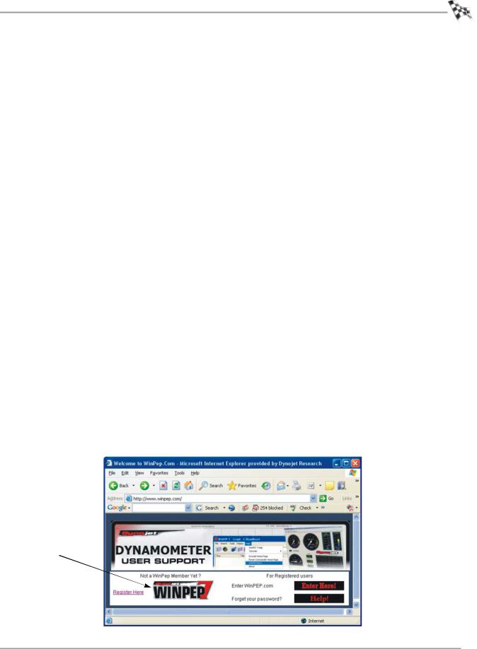
REGISTRATION
Registering your software helps Dynojet provide technical support and inform you about new software developments. To register, go to www.winpep.com.
click here to register
Figure 1-1: Registering Your Software
1-3
Version 2 |
WinPEP 7 User Guide |
C H A P T E R 1
WinPEP 7 Installation
WINPEP 7 INSTALLATION
. . . . . . . . . . . . . . . . . . . . . . . . . . . . . . . . . . .
Follow these steps to install WinPEP 7 on your computer.
Note: It is strongly recommended that you exit all other programs before running this install program.
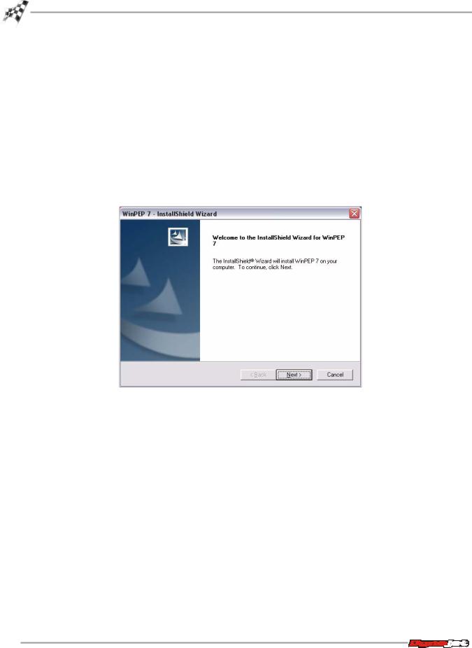
1Insert the WinPEP 7 CD in your CD-ROM drive. The launch program will run automatically showing the InstallShield Wizard, see Figure 1-2.
If auto-run is disabled on your computer, click Start on the Windows® task bar, and click Run. Type D:\setup.exe, where D is the letter that corresponds to your CD-ROM drive.
2Click Next to continue.
Figure 1-2: InstallShield Wizard Window
1-4
WinPEP 7 User Guide
S P E C I F I C A T I O N S A N D I N S T A L L A T I O N
WinPEP 7 Installation
3Carefully read the WinPEP 7 license agreement and click Next to continue.
To install WinPEP 7, you must accept this agreement. If you choose Cancel, the InstallShield Wizard will close.
Note: Be sure to read and understand the license agreement. A copy of the license agreement can be found in Appendix C of this manual.
Figure 1-3: Software License Agreement Window
4Select the setup type of installation you prefer and click Next to continue. For details on compact and custom installations, see “Custom Installation” on page 1-8.
Figure 1-4: Setup Type Window
1-5
Version 2 |
WinPEP 7 User Guide |

C H A P T E R 1
WinPEP 7 Installation
5Select the location where the WinPEP 7 software will be installed and click Next to continue.
Note: Dynojet recommends that you do not change the default destination folder.
Figure 1-5: Choose Destination Location Window
6 Enter your information and click Next to continue.
Figure 1-6: Shop Information Window
1-6
WinPEP 7 User Guide

S P E C I F I C A T I O N S A N D I N S T A L L A T I O N
WinPEP 7 Installation
7 Review the settings and click Next to begin copying files.
Figure 1-7: Start Copying Files Window
8 Click Finish to complete Setup.
Figure 1-8: InstallShield Wizard Complete Window
The installation is complete. You may now run WinPEP 7 by double-clicking the program icon installed on your desktop or on your start menu.
1-7
Version 2 |
WinPEP 7 User Guide |
C H A P T E R 1
WinPEP 7 Installation
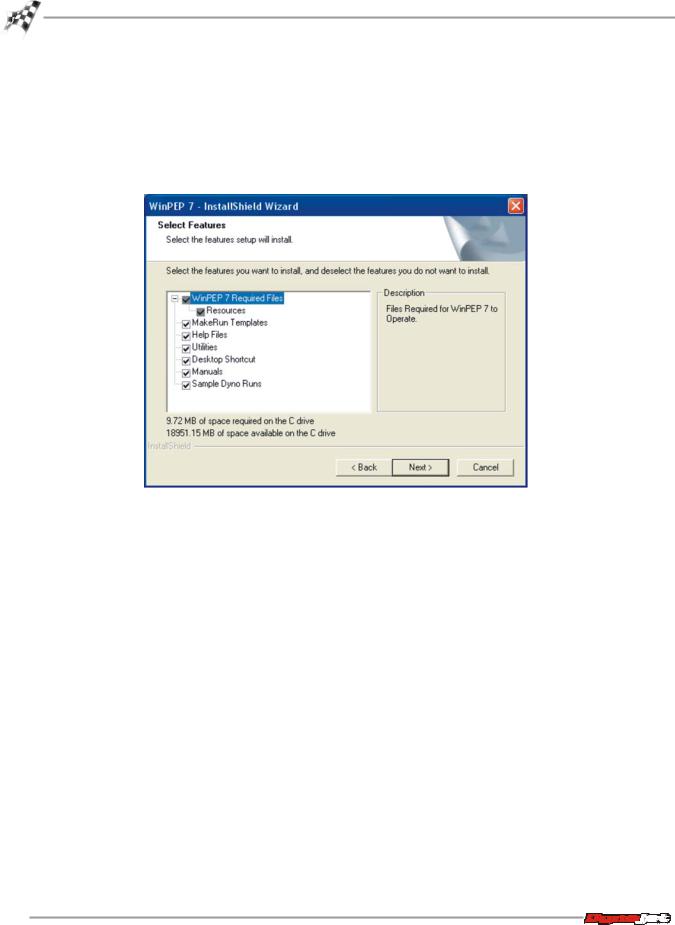
CUSTOM INSTALLATION
If you prefer to select which portions of the software are installed, choose Custom Install from the InstallShield Wizard Setup Type screen (refer to “Setup Type Window” on page 1-5). When you select Custom you will see the options shown in Figure 1-9. Use your mouse to select the features you want to install by selecting their boxes so that they appear checked.
Figure 1-9: Custom Install from InstallShield Setup Type
COMPACT INSTALLATION
The compact installation does not install the Help Files, Utilities, Desktop Shortcut,
Manuals, or Sample Runs.
1-8
WinPEP 7 User Guide

S P E C I F I C A T I O N S A N D I N S T A L L A T I O N
WinPEP 7 Installation
DYNAMIC HELP FILES
When you select the Complete Installation or choose a Custom Installation with the Manuals feature selected, a subfolder named Root is created within the WinPEP 7 folder. Any legitimate Adobe Portable Document Format (.pdf) file that is copied into this folder automatically appears listed in your help menu.
When you install WinPEP 7, manuals install that are useful for your type of dyno. For example, if you are using a motorcycle dyno, when you pick Help!Manuals you will see a listing for Motorcycle Dyno Manuals, but not necessarily for Automotive Dyno Manuals.
To add your own files to the Manuals list, simply use your desktop My Computer icon and copy any valid .pdf file into the folder named Root located inside the WinPEP installation folder.
The directory structure for the help files is shown in Figure 1-10.
Figure 1-10: WinPEP 7 Directory Structure for Help Files
1-9
Version 2 |
WinPEP 7 User Guide |
C H A P T E R 1
WinPEP 7 Installation
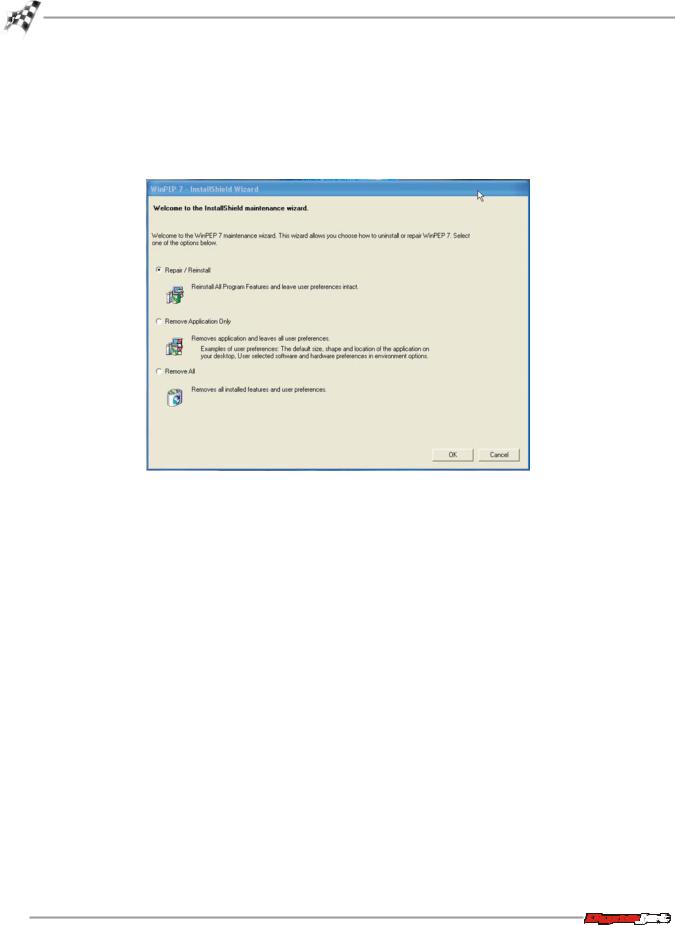
REMOVING OR REPAIRING AN INSTALLATION
If you have already installed WinPEP and you launch the setup program from the CDRom, the options to Remove/Repair, Remove Application Only, or Remove All will appear as shown in Figure 1-11. To remove an installation you can also use the Add or Remove Programs selection from the Control Panel.
Figure 1-11: Using WinPEP Setup Program to Remove or Repair an Installation
1-10
WinPEP 7 User Guide

C H A P T E R
2
DYNO AND WINPEP BASICS
Understanding the theory and layout of your WinPEP software helps you build a solid foundation upon which you can build advanced skills quickly.
In this chapter:
How Your Dyno Works, page 2-2
Hardware and Software, page 2-2
Theory of Operation, page 2-2
Dyno Electronics, page 2-4
Dyno Electronics Symbols, page 2-5
The Pendant, page 2-6
WinPEP 7 Software Interface, page 2-7
WinPEP 7 Menus, page 2-7
Using WinPEP 7 Help, page 2-8
Searching the User Manual, page 2-9
On-Line Manuals for Your Dyno, page 2-10
Tutorials, page 2-11
WinPEP 7 Dialog Boxes, page 2-12
Setting the User Level, page 2-14
Managing DynoRun Files, page 2-15
Creating a New Folder, page 2-17
Dyno Run Files, page 2-18
2-1
WinPEP 7 User Guide

C H A P T E R 2
How Your Dyno Works
HOW YOUR DYNO WORKS
. . . . . . . . . . . . . . . . . . . . . . . . . . . . . . . . . . .
Dynojet’s inertia dynamometer (dyno) is a measuring device for recording and displaying power and torque of an engine. Its method of measurement directly implements the engineering principles of power and torque. Correction factors assist in the comparison of these measurements under various test conditions, making computer hardware (your dyno electronics) and software (WinPEP 7) necessary to obtain, interpret, and display the data.
HARDWARE AND SOFTWARE
The dynamometer electronics acquire data, from the spinning dyno drum, necessary for power, torque, and correction factor calculations. This includes air temperature, absolute barometric pressure, humidity, drum timing, and engine RPM.
During a run, the data is stored in the dyno electronics memory.
After a dyno run is finished, data from the dyno electronics, calibration data, and user notes are saved to a file on the computer’s hard disk. When you use WinPEP to select a run, the data is loaded from the hard disk into computer memory. Data from up to twelve runs can be viewed in WinPEP at once.
The information collected can be used for viewing horsepower and torque graphs. Data can either be viewed as measured (“uncorrected”) or corrected to standard atmospheric conditions using WinPEP.
THEORY OF OPERATION
POWER
Power, in mechanical terms, is the ability to accomplish a specified amount of work in a given amount of time. By definition, one horsepower is equal to applying a 550 pound force through a distance of one foot in one second. In everyday terms, it would take one HP to raise a 550 pound weight up one foot in one second. So to measure horsepower, we need to know force (in pounds) and velocity (in feet per second).
Dynojet’s inertia dynamometer measures power just in this way. The dyno calculates velocity by measuring the time it takes to rotate the heavy steel drum one turn. The dyno measures force at the surface of the drum by indirectly measuring the drum’s acceleration. Acceleration is simply the difference in velocity at the surface of the drum from one revolution to the next. The force applied to the drum is calculated from acceleration using Newton’s 2nd law, F=MA, (F)orce equals (M)ass times (A)cceleration.
Power is coupled to the drum by friction developed between the driving tire of the vehicle and the knurled steel surface on the drum of the dynamometer.
TORQUE
When an object rotates around a point, the object’s speed of rotation depends on both an applied force and the moment arm. The moment arm is the distance from the
2-2
WinPEP 7 User Guide

D Y N O A N D WI N P E P B A S I C S
How Your Dyno Works
point of rotation to where the force is being applied. Torque is the product of the force and the moment arm. For example think about trying to spin a drum by wrapping a rope around the drum and then pulling on the rope. If the rope is wrapped around a drum of one foot radius and pulled with 550 pounds of force, the resulting torque is 550 foot-pounds.
The torque on the dyno’s drum can be calculated by multiplying the force applied by the drum’s radius. However, engine torque is not equal to the dyno’s drum torque because the gearing through the drive train changes the moment arm. The change in the moment arm is proportional to the ratio of engine speed to drum speed. Therefore, tachometer readings are necessary to calculate and display engine torque.
CORRECTION FACTORS
The calculation of horsepower, or the accuracy of a Dynojet dynamometer, is not dependent on the location or conditions during the measurement. The performance of the internal combustion engine however, is sensitive to atmospheric conditions, especially air density and air temperature. To compare power measurements taken at different times or places, it is necessary to compensate for differing atmospheric conditions.
Correction Factors are used to compensate for different operating conditions while measuring engine horsepower. The typical correction factor (CF) is calculated based on the absolute barometric pressure, air temperature and the water content of the air used for combustion by the engine under test. The correction factor attempts to predict the engine horsepower if the engine were tested at sea level under standard pressure and temperature conditions.
Absolute barometric pressure is a measure of how hard the air molecules are being pushed closer to one another. The unit of measurement is typically inches of mercury (inches Hg). The more pressure, the more molecules there are in a liter of air and the more air the engine “gobbles up” during the intake stroke. Absolute barometric pressure is equal to relative barometric pressure only at sea level. Relative barometric pressure is reported at airports and by weather barometers. A good approximation for converting relative barometric pressure to absolute barometric pressure is:
AbsHg = RelHg - (Elev/1000) Where:
AbsHg is Absolute barometric pressure. RelHg is Relative barometric pressure.
Elev is test location elevation in feet above sea level.
Humidity is the percentage of a volume of air that is occupied by water vapor. Water vapor displaces oxygen and reduces the amount of combustion air ingested during the intake stroke.
Air temperature is the temperature of the air entering the intake system of the engine under test. In some cases this is ambient air temperature, but in other cases the intake air is significantly heated by the engine and is different than ambient air. Heat tends to spread air molecules apart. So as temperature increases, there are less molecules in a liter of air and less air is swallowed during the intake stroke.
Dynojet’s WinPEP 7 software uses the SAE’s latest correction formula (June 1990). This formula assumes a mechanical efficiency of 85% and is much more accurate than earlier formulas at extreme conditions.
2-3
Version 2 |
WinPEP 7 User Guide |
C H A P T E R 2
Dyno Electronics
DYNO ELECTRONICS
. . . . . . . . . . . . . . . . . . . . . . . . . . . . . . . . . . .
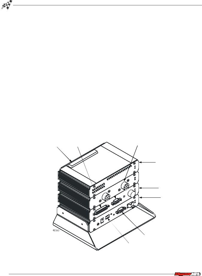
The standard dyno electronics package is comprised of four interconnected modules:
module |
|
description |
|
|
|
|
|
CPU Module |
|
Contains a 32-bit processor which acquires data from the |
|
|
|
expansion modules and communicates to the main |
|
|
|
computer running the WinPEP software. The processor |
|
|
|
queries the expansion modules to determine their identity |
|
|
|
and capabilities. |
|
|
|
|
|
Input/Output Module |
|
Sends and receives data from the dyno and the pendant. |
|
|
|
This module also contains a buzzer and a light which are |
|
|
|
activated when either the vehicle or the dyno speed limit |
|
|
|
is approached. |
|
|
|
|
|
RPM Module |
|
Receives and processes signals from up to two inductive |
|
|
|
pickups for measurement of engine RPM. Each input has |
|
|
|
an automatic gain circuit to compensate for a wide |
|
|
|
variance of ignition systems. |
|
|
|
||
Atmospheric Sensing Module |
Measures absolute pressure, air temperature, and relative |
||
|
|
humidity. The measurements are used by WinPEP to |
|
|
|
correct power and torque measurements to standard |
|
|
|
atmospheric conditions according to a DIN, SAE, or other |
|
|
|
formula. |
|
|
|
9-pin hand |
|
|
|
held pendant |
inductive pickup |
system expansion |
25-pin socket |
socket |
|
connector |
|
|
|
atmospheric sensing module
 RPM module
input/output module
CPU module
power
9-pin RS-232 socket
3-pin power plug
Figure 2-1: Dyno Electronics
2-4
WinPEP 7 User Guide
D Y N O A N D WI N P E P B A S I C S
Dyno Electronics
DYNO ELECTRONICS SYMBOLS
Symbols on the dyno electronics modules help you understand their function. A description of the module symbols and functions follows.
symbol |
description |
|
|
|
Shows when the module is receiving power. |
CPU module: the blue LED is lighted when data from the modules is being acquired and saved.
Input/Output module: the amber LED flashes proportionally to the dyno drum rpm.
Atmospheric Sensing module: the flashing amber LED indicates the module processor is operating properly.
Inputs for both primary and secondary inductive pickup clips. Either input may be used with a primary or secondary inductive pickup on a single ended coil. Both inputs can be used for a wasted spark ignition.
Connects to the 25-pin shielded cable from the dynamometer.
Connects to the 9-pin pendant cable.
Connects to the 9-pin RS-232 PC serial communications port.
Connects a synchronization signal to a third party data acquisition system.
Connects a 12 volt DC power to a third party data acquisition system.
Connects to a 12 volt DC power supply or battery. The adjacent LED glows bright green when power is properly connected.
When this switch is on, power is supplied to all connected modules.
Amber LED flashes at a steady rate when the power is on; flashes proportionally to the rpm when an rpm signal is detected, faster rpm equals faster blinking rate.
For more information on connecting your dyno electronics, see “Connecting the Dyno Electronics” on page 3-11.
2-5
Version 2 |
WinPEP 7 User Guide |

C H A P T E R 2
Dyno Electronics
THE PENDANT
The dyno electronics is equipped with a standard two-button pendant that lets you control sampling and braking from your vehicle. The pendant works with WinPEP 7; however, many of WinPEP 7’s newest features can only be controlled using the keyboard or mouse.
press this button |
to |
|
|
|
|
Red |
Turn on the emergency brake (apply 100% braking). |
|
|
|
|
Green |
Move to the next step in the run loop: |
|
|
• |
Start/stop sampling |
|
• |
Close Graph |
• Close special MakeRun dialog boxes
Click and hold to toggle load control on and off (available only when load control is supported)


 green button
red button
Figure 2-2: Standard Two Button Pendant
2-6
WinPEP 7 User Guide

D Y N O A N D WI N P E P B A S I C S
WinPEP 7 Software Interface
WINPEP 7 SOFTWARE INTERFACE
. . . . . . . . . . . . . . . . . . . . . . . . . . . . . . . . . . .
WinPEP 7 is designed to be user-friendly and intuitive. Once you understand the basic layout, it will be easy for you to obtain information efficiently. This section provides a quick look at standard interface controls, as well as features unique to WinPEP 7.
WinPEP 7 menus and dialog boxes conform to Microsoft Windows® conventions— with a few enhancements. If you are new to Windows®, consult the documentation resources provided with your computer for complete information about using Windows®.
The Graph screen is displayed by default when WinPEP 7 opens.
title bar
menus |
|
|
|
graph toolbar |
|
|
|||
navigation |
|
|
|
|
|
|
|
|
|
toolbar |
|
list view |
||
|
|
|
|
|
tree view |
|
axis selection |
||
|
|
|
|
|
|
|
|
|
button |
|
axis channel |
|
|
|
label |
|
|
axis |
|
|
channels |
axis channel |
|
|
label |
|
|
graph display |
|
|
axis channel |
|
|
|
|
|
label |
scale mode display |
|
Figure 2-3: Graph Features
WINPEP 7 MENUS
There are two types of menus available in WinPEP 7. The menu bar, located across the top of the screen, and pop-up menus that are available when you right click key areas, such as: the TreeView, Graph Display, and ListView.
The menu bar displays the five menus available in WinPEP 7: File, Search, Tools, Display, and Help. Each menu contains groups of related commands. Some commands will be disabled depending on which screen you are currently in. Many commands have a keyboard shortcut list after their name. You will learn more about the menu bar in “The WinPEP 7 Menu Bar” on page 3-17.
menu choices
 keyboard shortcut
commands
Figure 2-4: WinPEP 7 Menus
2-7
Version 2 |
WinPEP 7 User Guide |

C H A P T E R 2
Using WinPEP 7 Help
USING WINPEP 7 HELP
. . . . . . . . . . . . . . . . . . . . . . . . . . . . . . . . . . .
WinPEP 7 includes complete documentation in online Help. From the WinPEP 7 menu bar, choose Help to display the Help menu as shown in Figure 2-5. You can also visit www.winpep.com to find user manuals and technical support.
enlarged view showing help menu
help menu
Figure 2-5: Help Menu
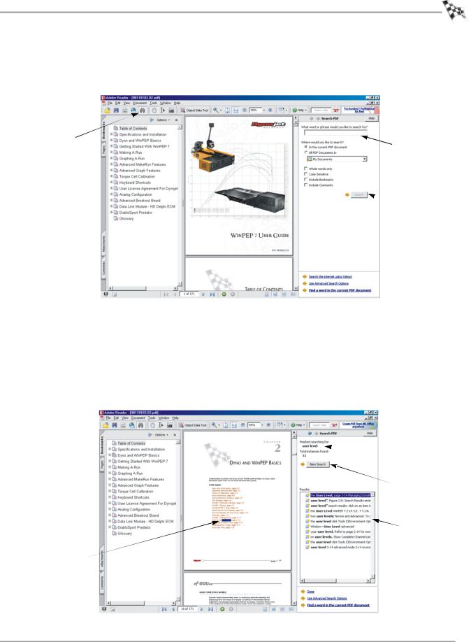
Click Help !WinPEP 7 User Guide to show this user manual as a Public Document Format (.pdf) file that you can browse and search.
Note: To display the manuals, you must have a program capable of displaying
.pdf files installed. Dynojet recommends Adobe Reader 6.0 or higher.
search icon 
click item to browse file
click plus sign (+)  to expand contents
Figure 2-6: On-Line User Manual
2-8
WinPEP 7 User Guide
D Y N O A N D WI N P E P B A S I C S
Using WinPEP 7 Help
SEARCHING THE USER MANUAL
•Click the Search icon (which looks like a pair of binoculars) to search the on-line user manual. The search window opens on your screen as shown in Figure 2-7.
search icon 
 enter word or phrase to search for
 click search button to display results
Figure 2-7: Search the User Manual
•Enter your search in the field below the prompt, “What Word or Phrase Would You Like to Search For?”
•Click the Search button or press the Enter key. The results of your search will be displayed as shown in Figure 2-8.
•Click on the items displayed in the right hand column under Results in order to jump to that section of the manual. Figure 2-8 shows the results when searching for the phrase “user level”.
 search for the
  phrase “user level”
 new search button
 search results: click on an item to jump
to that section of highlighted search  the manual
result
Figure 2-8: Search Results
2-9
Version 2 |
WinPEP 7 User Guide |
C H A P T E R 2
Using WinPEP 7 Help
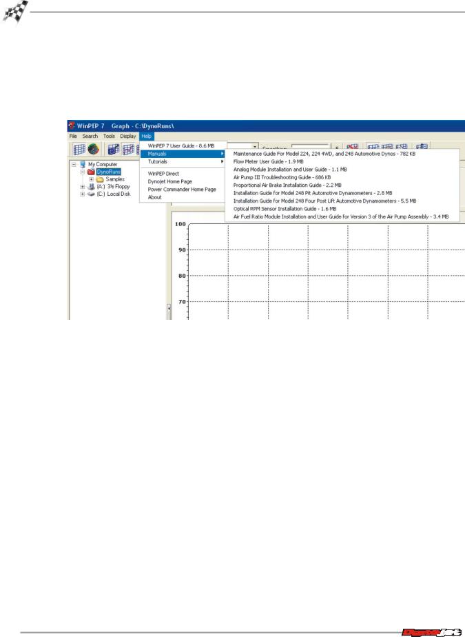
ON-LINE MANUALS FOR YOUR DYNO
On-line manuals are also available as .pdf files by choosing Help !Manuals and selecting the manual you would like to view. In addition to the manuals provided by Dynojet, you can also add your own .pdf files to the directory \WinPEP 7\Root in order to see your own company manuals displayed on the help menu.
Figure 2-9: On-Line Manuals
2-10
WinPEP 7 User Guide
D Y N O A N D WI N P E P B A S I C S
Using WinPEP 7 Help
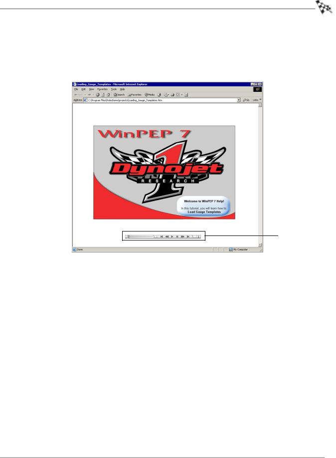
USING THE TUTORIALS
You can watch video tutorials by choosing Help !Tutorials and selecting the tutorial you would like to view. Use the navigation bar in the tutorial to stop, pause, move forward, or go back at any time during playback.
navigation bar
Figure 2-10: Video Tutorial Navigation Bar
2-11
Version 2 |
WinPEP 7 User Guide |
C H A P T E R 2
WinPEP 7 Dialog Boxes
WINPEP 7 DIALOG BOXES
. . . . . . . . . . . . . . . . . . . . . . . . . . . . . . . . . . .
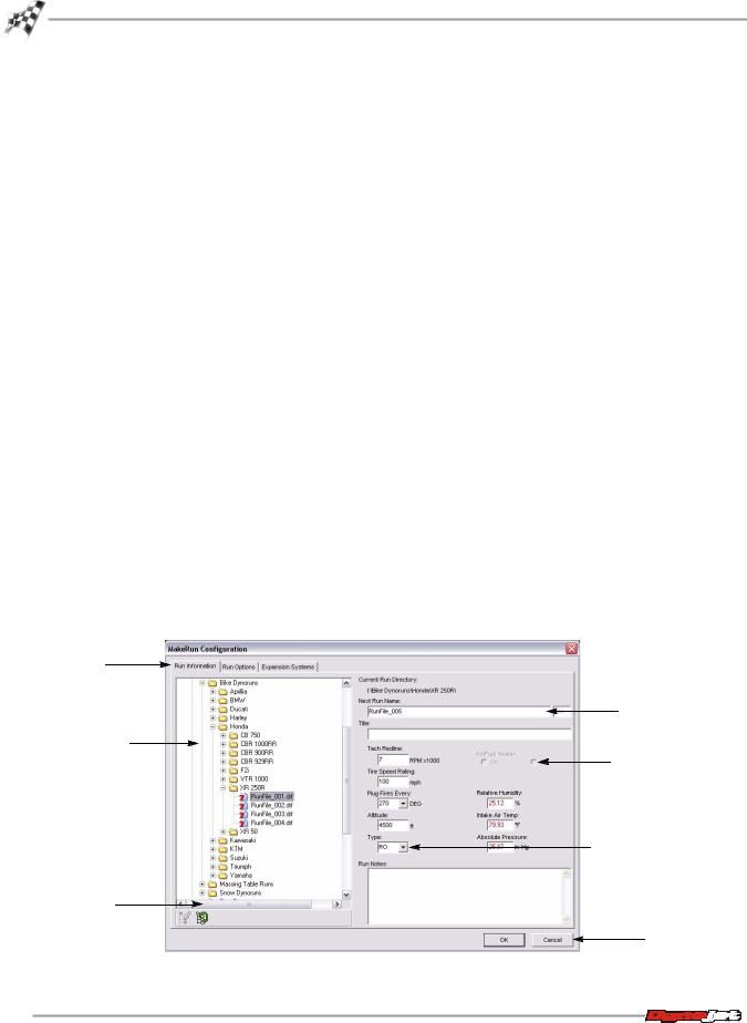
Many menu items display dialog boxes after you select them. An example is shown in Figure 2-11. The dialog boxes in WinPEP 7 consist primarily of tabs, fields, drop-down lists, radio (option) buttons, check boxes, and buttons.
Page Tabs—Many dialog boxes provide multiple functions through tabs. By clicking a tab icon, you can display different sets of controls.
Fields—A field is a rectangular box for entering a specific value or information. For example, you can enter the run name in the Next Run Name field shown in Figure 2- 11.
You can use the tab key to highlight the next field in a dialog box and shift+tab to highlight the previous field.
Drop-down Lists—A drop-down list is a small menu within a dialog box. A dropdown list contains various options for you to choose from. Click on the arrow to reveal the list.
Radio (Option) Buttons—A radio button lets you select options or turn options on and off. Selecting a radio button may activate other controls and may expand a dialog box to display more controls.
Check Boxes—A check box lets you turn options on and off. Selecting a check box may activate other controls and may expand a dialog box to display more controls.
Buttons—A button performs an action. If a button has a bold outline, you can press Enter when in any field of a dialog box to activate the button, rather than clicking the button with your mouse. A button may also include a drop-down list that lets you choose a type of action.
page tab
field
tree view
radio button
drop-down list
scroll bar
button
Figure 2-11: WinPEP 7 Dialog Box Features
2-12
WinPEP 7 User Guide

D Y N O A N D WI N P E P B A S I C S
WinPEP 7 Dialog Boxes
Open, Save As Dialog boxes—These dialog boxes are used to open or save files; they include standard Windows® controls for navigating through disks and folders so you can locate files, or choose where you want to save files. WinPEP 7 includes additional areas for previewing graphs, notes, and titles.
browse directories 
locate files
graph preview
Figure 2-12: Open Dialog Box
Warning Dialog Box—A warning dialog box alerts you when there is a problem and often suggests a solution.
Figure 2-13: Warning Dialog Box
POWER THROUGH KEYBOARD COMMANDS
As you use WinPEP 7, you will develop your own working style. Maybe you will prefer to use the mouse and menu commands or you may find that you prefer the quick access to features provided by keyboard commands. A list of keyboard commands is available in
2-13
Version 2 |
WinPEP 7 User Guide |
C H A P T E R 2
Setting the User Level
SETTING THE USER LEVEL
. . . . . . . . . . . . . . . . . . . . . . . . . . . . . . . . . . .
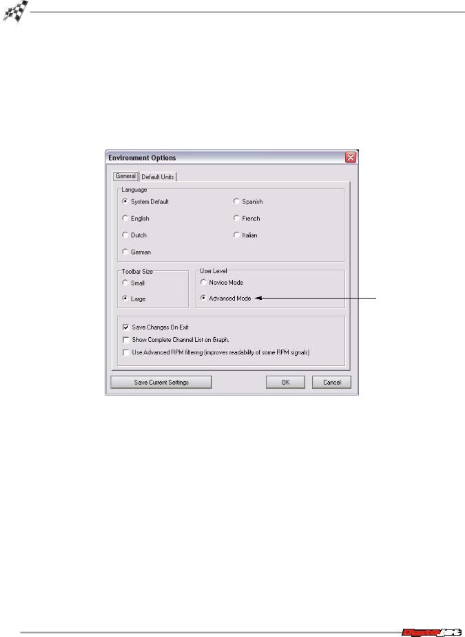
WinPEP 7 lets you work in two user levels: Novice and Advanced. To change the user level click Tools !Environment Options and click on the General tab.
WinPEP 7 defaults to Advanced Mode. Dynojet recommends you use Advanced Mode. Advanced Mode enables all WinPEP 7 features and functions giving you complete control over the software.
advanced mode
Figure 2-14: Environment Options Window—User Level
2-14
WinPEP 7 User Guide
Loading...