

Page 1

INSTALLATION
/ USER’S
GUIDE
THIS GUIDE COVERS THE INSTALLATION AND USE OF THE
TARGET TUNE ACCESSORY FOR DYNOJET POWER VISION
PARTS LIST
1 - Target Tune Module
1 - Installation Guide
3 - 8" Cable Ties
2 - Dual Lock strips
1 - Alcohol Swab
2
2 - O
1 - Y-Adapter Cable *
2 - 18mm O
2 - O
Sensor Bungs *
2
Sensors *
2
Sensor Cables *
Parts shown with an asterisk (*) are
excluded in Target Tune kits that have
a part number ending in “X.” These
kits are intended for users that are
upgrading from PV Auto Tune to PV
Target Tune. These users should
already have these specific parts
installed from the previous PV Auto
Tune kit.
!!! IMPORTANT PLEASE READ FIRST !!!
The Target Tune module requires the use of (2) 18mm O
system doesn’t have bungs pre-installed, bungs will have to be welded into the header
pipes to use this module.
Your bike’s ECM will need to be flashed by the Power Vision with a tune that enables
Target Tune.
SOFTWARE AND OTHER TECHNICAL INFORMATION ARE AVAILABLE ONLINE AT:
WWW.FLASHYOURHARLEY.COM.
2191 Mendenhall Drive North Las Vegas, NV 89081
1-800-992-4993 www.dynojet.com
2
sensors. If your bike’s exhaust
Target Tune Installation - 1
Page 2

APPLICATION GUIDE
Target Tune Part Number Application Description
2-pin stock O2 connectors
(1 long leg and 1 short leg), 4-pin
diagnostic connector
* 2011 Softail models will require
splicing of the TT module’s power
and ground supply wires; or for
a cleaner install with OEM style
connections a 6-pin Y-adaptor
(PN: 76950389) and a 6-pin to
4-pin adaptor (PN: 76950664)
can be purchased separately.
TT-1 & TT-1X
2007-2011 Softail *
2007-2009 Touring
2008-2011 V-Rod **
2006-2011 Dyna
2007-2013 Sportster
TT-2 & TT-2X 2010-2013 Touring
TT-3 & TT-3X 2012-2015 V-Rod
2012-2015 Softail
TT-4 & TT-4X
2012-2015 Dyna
TT-5 & TT-5X 2014-2015 Touring
TT-6 & TT-6X 2015 Street 500/750
TT-7 & TT-7X 2014-2015 Sportster
** 2008-2011 V-Rod models will
require splicing of the TT module’s
power and ground supply wires; or
for a cleaner install with OEM style
connections a power extension
lead (PN: 76950159) can be
purchased separately.
4-pin stock O2 connectors
(2 short legs), 4-pin diagnostic
connector
4-pin stock O2 connectors
(1 long leg and 1 short leg), 4-pin
diagnostic connector
4-pin stock O2 connectors
(1 long leg and 1 short leg), 6-pin
diagnostic connector
4-pin stock O2 connectors
(2 short legs), 6-pin diagnostic
connector
4-pin stock O2 connectors
(special length), 6-pin diagnostic
connector
4-pin stock O2 connectors
(special length), 6-pin diagnostic
connector
Note: Target Tune kits that have a part number ending in “X” contain Target Tune modules only. There is no
O2 sensor hardware or Y-adapters supplied in these kits. These are intended for users that are upgrading
from PV Auto Tune to PV Target Tune. These users should already have wideband O2 sensor hardware
and Y-adapters installed from the previously installed PV Auto Tune kit.
Dynojet Power Vision
Target Tune Installation - 2
Page 3

PRODUCT OVERVIEW
The Dynojet Target Tune accessory for Power Vision is a product that can add
a new dimension to your Harley-Davidson’s® ECM.
When paired with a Target Tune specific calibration flashed by a Power Vision,
your ECM will run closed loop fuel control based on wideband O2 sensors installed
into the exhaust, rather than the stock narrowband O2 sensors. The Power Vision
delivered calibration changes the coding in the ECM to “understand” the wideband
signal (from Target Tune) and allows the ECM to accurately achieve the target AFR
specified in the commanded air/fuel ratio table of your ECM’s tune. The ECM also
does this at all available engine ranges (not just light throttle cruising speeds).
Dynojet has evolved the OEM closed loop, adaptive fuel control system on your
Harley to meet the needs of performance enthusiasts.
Key Features:
• Allows the factory ECM to interpret and use wideband O2 sensor signals*
• Target fuel table from the calibration / tune is achieved in real time
• Retains OEM closed loop, adaptive fuel control strategy
• Learns and uses VE table corrections as you ride
• Does NOT interfere with dealer diagnostic / service tools
• Includes OEM style connectors to plug into factory O2 harness, either 2-pin
or 4-pin versions
• Fits 2006 and newer Harley Davidson® Bikes**
* Requires Power Vision Target Tune specific calibration
** ECM must be “closed loop capable” and have OEM wiring for O2 sensor circuitry.
Dynojet Power Vision
Target Tune Installation - 3
Page 4
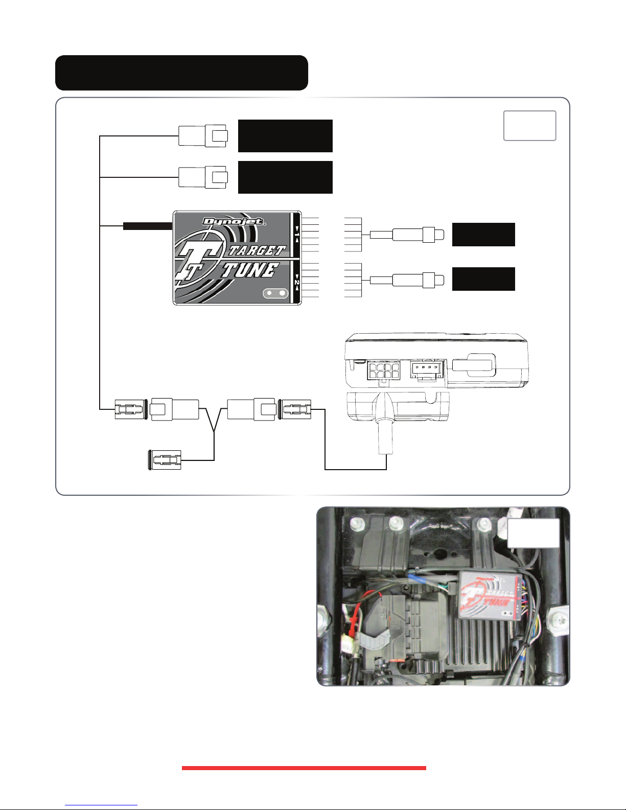
HARDWARE INSTALLATION
YELLOW/ORANGE
YELLOW/GREEN
STOCK O2 CONNECTOR
(FRONT)
STOCK O2 CONNECTOR
(REAR)
BLUE
RED
YELLOW
BLACK
GREY
WHITE
BLUE
RED
YELLOW
BLACK
GREY
WHITE
O2 SENSOR
O2 SENSOR
FIG. A
FRONT
REAR
TO VEHICLE
1. Find a location to mount the Target Tune module
and secure it with the supplied Dual Lock strips.
You can typically find a place under the bike’s
seat or behind a sidecover to mount it. Be sure
to choose a location within the harnesses’ reach
of the diagnostic connector and stock O2 sensor
connectors.
FIG. B
The top of the ECM is typically a good mounting
location for most Touring models (Fig. B).
Dynojet Power Vision Target Tune Installation - 4
Page 5

FIG. C
Diag Connector
FIG. D
TT Module
Diag Connector
On many Softail models you can typically find a place
under the seat to store the module (Fig. C). It
could go in the recess at the top of the battery,
on the side of the battery, on the relay bracket, or
even directly on the rear fender.
FIG. E
TT Module
On Sportsters, the left side of the battery is usually
the best location to secure the module (Fig. E).
On Dyna models you can typically fit the Target Tune
module inside the electrical box next to the ECM
(Fig. D).
FIG. F
TT Module
On V-Rod models, the best location to secure the
module is directly under the seat (Fig. F).
2. Install both of the supplied 18mm wideband O2 sensors into the exhaust system. (See “O2 Sensor Bung
Installation” section for guidelines if 18mm x 1.5 bungs need to be welded.)
3. Connect an O2 sensor cable to the front cylinder O2 sensor and route harness along the frame or stock wiring
harnesses going towards the Target Tune module.
4. Connect the other O2 sensor harness to the rear cylinder O2 sensor and route the harness along the frame or
stock wiring harnesses going towards the Target Tune module.
Note: Keep harnesses away from HOT and/or moving parts to prevent damage.
Note: If the supplied cables have different lengths, the longer cable should go to the front cylinder.
5. Connect the front cylinder O2 sensor harness to Target Tune module input #1 per Fig. A.
Connect the rear cylinder O2 sensor harness to Target Tune module input #2 per Fig. A.
Note: The harness can be cut to length if desired.
Note: To make inserting the wires into the module easier, first poke the hole with a paperclip or similar device. Also
tinning the bare wire ends with solder can help.
Dynojet Power Vision
Target Tune Installation - 5
Page 6

6. Locate and unplug the stock O2 sensor connections.
You can trace the cables from the stock O2 sensors
in the exhaust to these connectors.
7. Plug the connectors from the Target Tune into the
stock O2 sensor connectors (Fig. A).
• Plug the Target Tune lead with the YELLOW/
ORANGE wire into the FRONT cylinder stock O2
connector.
FIG. G
Rear O2
• Plug the Target Tune lead with the YELLOW/GREEN
wire into the REAR cylinder stock O2 connector.
Note: The stock O2 sensors will no longer be
connected to anything and can be removed from the
exhaust if desired, and if you have a way to plug the
holes in the exhaust.
FIG. Ha
FIG. Hb
Front O2
Rear O2
On 2007-2009 Touring models and 2007-2011
Softails the stock O2 connectors for the front
cylinder are found at the front of the engine
near the voltage regulator (Fig. Ha), and the rear
cylinder O2 sensors connectors are found at the
rear of the engine near the oil tank (Fig Hb).
Front O2
On 2010-2015 Touring models the stock O2
connectors are found behind the right-hand side
cover (Fig. G).
FIG. Ja
FIG. Jb
Front O2
Rear O2
On 2012-2015 Softails the stock O2 connectors
for the front cylinder are found at the front of the
engine near the voltage regulator (Fig. Ja), and
the rear cylinder O2 sensor connectors are found
under the seat near the battery (Fig Jb).
FIG. Ka
FIG. Kb
Rear O2
Front O2
On 2006-2015 Dyna models the stock O2
connectors for the front cylinder are found at the
front of the engine near the voltage regulator (Fig.
Ka), and the rear cylinder O2 sensor connectors
are found under the seat (Fig Kb).
Dynojet Power Vision
FIG. La
FIG. Lb
Rear O2
Front O2
On Sportsters the front O2 connection is always at
the front of the engine on the left side near the oil
filter (Fig. La). The rear O2 connection is above
the battery on 2014-2015 models (Fig. Lb) or
just rear of the engine on 2007-2013 models (not
pictured).
Target Tune Installation - 6
Page 7
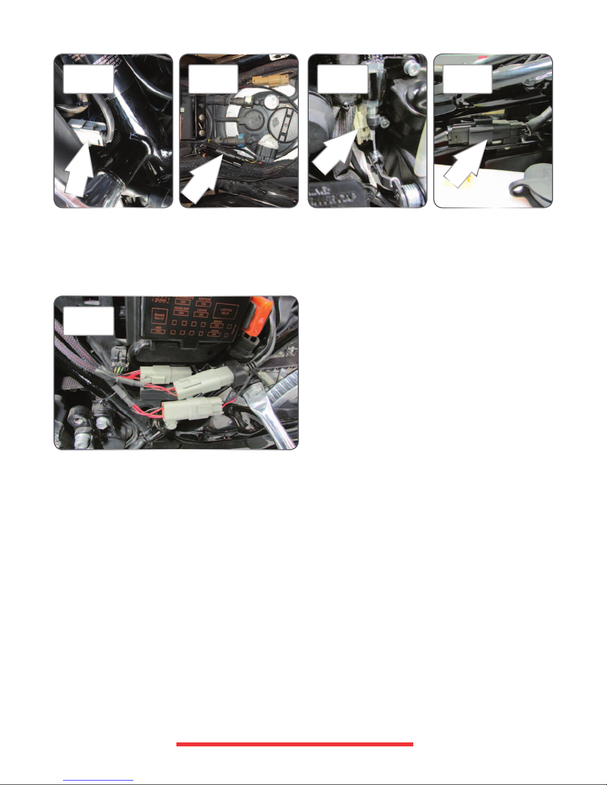
FIG. Ma
Front O2
FIG. Mb
Rear O2
FIG. Na
Front O2
FIG. Nb
Rear O2
On V-Rods the front O2 connection is always on the
left side of the radiator (Fig. Ma). You may need
to loosen the radiator shroud to gain access to it.
The rear O2 connection is under the seat near the
fuel filler (Fig. Mb).
FIG. O
On Street models (500 and 750), the front O2
connector is located on the right side of the
bike between the swingarm pivot shaft and the
engine case (Fig. Na). The rear O2 connector is
behind the left hand sidecover above the coolant
reservoir (Fig. Nb).
8. Connect the supplied Y-Adaptor to the Diagnostics
port on the motorcycle. (See “Diagnostic Connector
Locations” of the PV Quick Start guide for model
specific diagnostic connector locations.)
9. Route and connect the power lead from the Target
Tune module to one side of the Y-adaptor.
• 2008-2011 V-Rod models will require splicing of the
TT module’s power and ground supply wires; or for a
cleaner install with OEM style connections a power
extension lead (PN: 76950159) can be purchased
separately. If you are splicing the power supply,
the TT’s BLACK wire can go to a constant chassis
ground source such as the frame or the engine case.
The TT’s RED wire will need to go to a key-switched
12v power source.
Dynojet Power Vision
• 2011 Softail models will require splicing of the
TT module’s power and ground supply wires; or
for a cleaner install with OEM style connections a
6-pin Y-adapter, PN: 76950389, and a 6-pin to
4-pin adaptor, PN: 76950664, can be purchased
separately. If you are splicing the power supply,
the TT’s BLACK wire can go to a constant chassis
ground source such as the frame or the engine case.
The TT’s RED wire will need to go to a key-switched
12v power source.
10. Connect the Power Vision cable to the other side of
the Y-adaptor (Fig. O).
11. Tie up and secure any loose sections of the wiring
with the supplied zip-ties and verify wiring is free and
clear of abrasion and heat sources.
Target Tune Installation - 7
Page 8

O2 SENSOR BUNG INSTALLATION
1. Find a suitable location to install the included
M18 x 1.5mm bungs on the exhaust system.
Note: Suitable locations may vary depending on
exhaust system. (See Fig. A and B)
2. Mount the bungs in a manner that reduces the
risk of moisture contamination to the sensor, as
condensation can build up in the exhaust system.
Ideally, the sensor should be between the 10
o’clock and 2 o’clock position on the pipe. A 10°
incline of the sensor above the horizon line should
be considered a minimum. (See Fig. C)
3. Mark the pipe where bungs will be mounted.
FIG. A
REAR Location
FIG. B
Note: Adequate room will be needed for the sensor
body and wiring.
4. Remove the exhaust system.
5. Drilling and welding of the exhaust system should
be done by an experienced welder/fabricator.
6. Reinstall the exhaust system.
O2 SENSOR CONDITION TEST
The Target Tune kit has a built in function
which allows you to test the sensor accuracy
and condition.
1. Remove the sensors from the exhaust system and
hold in ambient air.
2. Verify the Target Tune kit has been powered up for
at least 1 minute and has a solid light.
3. Press and hold the function button on the front
of the Target Tune kit for 3 seconds to initiate the
test on sensor #1 and release the button once the
light begins to blink rapidly.
FRONT Location
FIG. C
4. The LED light will blink rapidly, pause for a
moment, and then begin to flash a series of long
blinks before going back to solid. (You may get
zero blinks before going completely solid, which
would indicate a perfect condition if at or near
sea-level.)
5. Count the number of long blinks and refer
to the chart.
6. Initiate the test a second time to get results for
sensor #2.
7. Retest the sensors if there is any question as to
the purity of the air during the test.
Dynojet Power Vision
Target Tune Installation - 8
Page 9

PROGRAMMING THE ECM
Target Tune requires a special calibration to be flashed to your ECM in order to function
properly. You will need to send an e-mail request to targettune@dynojet.com. Calibrations
submitted to make the Target Tune function properly can be:
• Copy of original or current tune
• Custom tunes
• Pre-configured tunes from Dynojet
The original tune that is being modified to work with Target Tune should be as optimal as
possible for the engine and modifications that you are using. This means if you have a very
unique or radical engine build, you may need to have a more optimal starting point tune
developed by other means before Target Tune can work effectively. This might be a tune
developed by a professional dyno tuner, a tune custom made by Dynojet staff, or a tune
developed by Auto-tune Basic or Auto-tune Pro methods.
Note: The Target Tune module can be used in place of the Auto-tune module when using the
Auto-tune Pro feature; but does require an additional CAN link cable that is sold separately
(PN: 76950427) and calibration changes.
If you’d like to use the tune that’s currently flashed to your ECM please follow these steps in
order to read it from your ECM:
1. Plug the Power Vision into the bike’s diagnostic port.
2. Turn the bike to the ON position (key ON, Run/Stop switch to “Run”, engine stalled).
3. Go to Vehicle Tools on the Power Vision.
4. Select Read ECM. Follow the prompts to read the ECM.
5. Turn the key OFF.
6. Remove the Power Vision and bring it to a computer with Dynojet WinPV software installed.
7. Connect a USB cable to the Power Vision.
8. After the Power Vision boots up and says “PC Link Mode Active,” launch the WinPV software.
9. On the menu bar, go to “Power Vision”, and choose “Diagnostic Test functions > Get ECM
Data from PV”.
10. Look for the “.stk” file (something like this…..10-FB4-JHMKORL.stk ).
11. Select the file and save it to your Personal Computer for safe keeping. (WinPV may have
already done this for you.)
12. E-mail the original .stk file to targettune@dynojet.com.
Note: The latest instructions and software pertaining to Target Tune, please visit:
http://www.dynojet.com/powervision
Dynojet Power Vision
Target Tune Installation - 9
 Loading...