

Page 1
Page 2

©2006 Dynojet Research, Inc. All Rights Reserved.
Spring Applied Air Release (SAAR) Brake Assembly Installation
This manual is copyrighted by Dynojet Research, Inc., hereafter referred to as Dynojet,
and all rights are reserved. This manual, as well as the software described in it, is
furnished under license and may only be used or copied in accordance with the terms of
such license. This manual is furnished for informational use only, is subject to change
without notice, and should not be construed as a commitment by Dynojet. Dynojet
assumes no responsibility or liability for any error or inaccuracies that may appear in this
manual. Except as permitted by such license, no part of this manual may be reproduced,
stored in a retrieval system, or transmitted, in any form or by any means, electronic,
mechanical, recording, or otherwise, without the prior written permission of Dynojet.
The Dynojet logo is a trademark of Dynojet Research, Inc.
Any trademarks, trade names, service marks, or service names owned or registered by any
other company and used in this guide are the property of their respective companies.
Dynojet Research, Inc., 2191 Mendenhall Drive, North Las Vegas, Nevada 89081, USA.
Printed in USA.
Part Number: 98212104 Version 01 (06/06)
Page 3

T
ABLE OF
C
ONTENTS
Spring Applied Air Release (SAAR)
Brake Assembly Installation
Introduction . . . . . . . . . . . . . . . . . . . . . . . . . . . . . . . . . . . . . . . . . . . . . . . . . . . 2
Technical Support . . . . . . . . . . . . . . . . . . . . . . . . . . . . . . . . . . . . . . . . . . . . 2
The Hydraulic Brake Assembly . . . . . . . . . . . . . . . . . . . . . . . . . . . . . . . . . . . . 4
Preparing to Remove the Hydraulic Brake . . . . . . . . . . . . . . . . . . . . . . . . . . 5
Removing the Hydraulic Brake Assembly . . . . . . . . . . . . . . . . . . . . . . . . . . . 7
Installing the SAAR Brake Assembly . . . . . . . . . . . . . . . . . . . . . . . . . . . . . . . 12
Installing the Brake Weldment and Brake Shoes . . . . . . . . . . . . . . . . . . . . . 12
Installing the Air Can Mount and Tube . . . . . . . . . . . . . . . . . . . . . . . . . . . 14
Installing the Air Can . . . . . . . . . . . . . . . . . . . . . . . . . . . . . . . . . . . . . . . . . 16
Connecting to the Breakout Board . . . . . . . . . . . . . . . . . . . . . . . . . . . . . . . 18
Connecting to the Shop Air . . . . . . . . . . . . . . . . . . . . . . . . . . . . . . . . . . . . 18
Fastening the Air Can . . . . . . . . . . . . . . . . . . . . . . . . . . . . . . . . . . . . . . . . 19
Powering up and Testing . . . . . . . . . . . . . . . . . . . . . . . . . . . . . . . . . . . . . . 19
Four Wheel Drive Dynos . . . . . . . . . . . . . . . . . . . . . . . . . . . . . . . . . . . . . . . . 20
Upgrading the Moveable 224 Dyno . . . . . . . . . . . . . . . . . . . . . . . . . . . . . . 20
Connecting the Movement Board and Shop Air . . . . . . . . . . . . . . . . . . . . . 20
Spring Applied Air Release (SAAR) Brake Assembly Installation
i
Page 4

Page 5

S
PRING
This document provides instructions for installing the Spring Applied Air Release
Brake Assembly (P/N 77010008) as an upgrade to model 224 Automotive
Dynamometers (dynos). To ensure safety and accuracy in the procedures, perform
the procedures as they are described.
Document Part Number: 98212104
Version 1
Last Updated: 06-21-06
A
B
RAKE
PPLIED
A
SSEMBLY INSTALLATION
AIR R
ELEASE
(SAAR)
Spring Applied Air Release (SAAR) Brake Assembly Installation
1
Page 6
SPRING APPLIED AIR RELEASE (SAAR) BRAKE ASSEMBLY INSTALLATION
Introduction
INTRODUCTION
. . . . . . . . . . . . . . . . . . . . . . . . . . . . . . . . . . .
The Spring Applied Air Release (SAAR) Brake Assembly (P/N 77010008) may be used
to replace the hydraulic brake on model 224 dynamometers. This guide provides
instructions for removing the hydraulic brake and installing the SAAR brake assembly.
The SAAR brake provides braking to the dyno drum through the use of a spring
applied brake mechanism. By default, the brake shoes are pressed against the dyno
drum by the spring mechanism. Air applied to the SAAR brake moves the brake shoes
away from the drum, releasing the brake.
The SAAR brake provides the following advantages over the previous hydraulic brake:
• Vehicles are easier to load since the SAAR brake is applied when the dyno is idle
• The SAAR brake provides braking in the event of a loss of power or an air supply
failure.
• Brake maintenance is reduced as the SAAR brake does not need the filling and
bleeding required for hydraulic brakes.
For more detailed information on the 224 dyno, refer to the Installation Guide for
Model 224 Above Ground Automotive Dynamometers (P/N 98210108) or the
Installation Guide for In Ground Model 224 Automotive Dynamometers (P/N
98210100).
CONVENTIONS USED IN THIS MANUAL
The conventions used in this manual are designed to protect both the user and the
equipment.
example of convention description
The Warning icon indicates potential harm to the
person performing a procedure and/or the
dynamometer equipment.
TECHNICAL SUPPORT
For assistance, please contact Dynojet Technical Support at 1-800-992-3525, or write
to Dynojet Research at 2191 Mendenhall Drive, North Las Vegas, NV 89081.
Visit us on the World Wide Web at www.dynojet.com where Dynojet provides state of
the art technical support, on-line shopping and press releases about our latest
product line.
Do not repair or replace any part of the dynamometer or attempt any servicing
unless specifically recommended in published user-repair instructions that you
understand and have the skills to carry out.
2
Spring Applied Air Release (SAAR) Brake Assembly Installation
Page 7
SPRING APPLIED AIR RELEASE (SAAR) BRAKE ASSEMBLY INSTALLATION
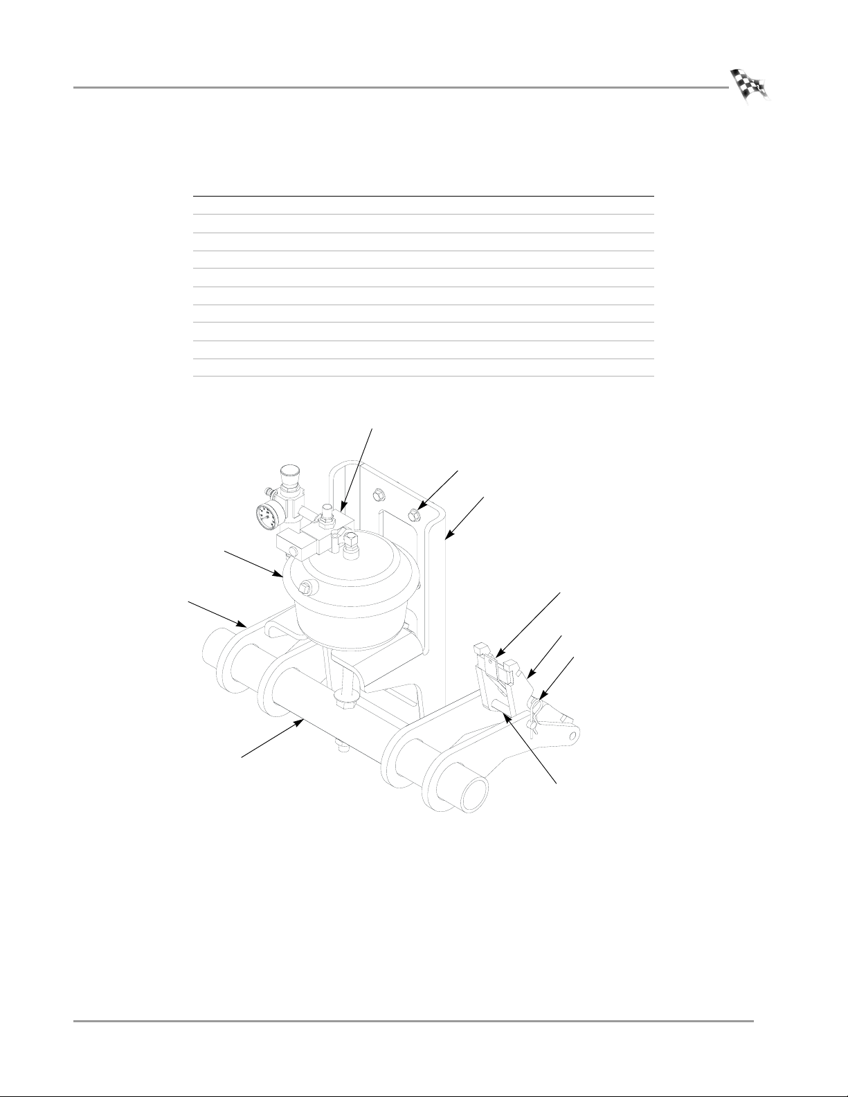
77010008 Spring Applied Brake Upgrade, 224
Stock Code Description Quantity
21612112 Mount, Air Can, Upgrade, 224 1
21612400 Brake Arm, 24 4
21612900 Brake Shoe Retainer, 224 2
21612901 Brake Actuating Tube, 224 1
32904080 Hairpin Cotter, 7/16"-3/4" 4
32916144 Clevis Pin, 1/2" x 4-1/2" 2
34761003 Air Canister, Type R30 1
36582471 Bolt, 3/8-16 x 1-1/2", Flange-Hex 4
61312105 Brake Holder Weldment, 224 2
64111005 Brake Solenoid Assembly, 224-2 1
brake solenoid
assembly
3/8-16 x 1-1/2" bolt
Introduction
air canister
brake arm
brake actuating tube
air can mount
AB090
Figure 1: Spring Applied Brake Upgrade
brake shoe retainer
brake holder weldment
hairpin cotter
clevis pin
Version 1 Spring Applied Air Release (SAAR) Brake Assembly Installation
3
Page 8
SPRING APPLIED AIR RELEASE (SAAR) BRAKE ASSEMBLY INSTALLATION
The Hydraulic Brake Assembly
THE HYDRAULIC BRAKE ASSEMBLY
. . . . . . . . . . . . . . . . . . . . . . . . . . . . . . . . . . .
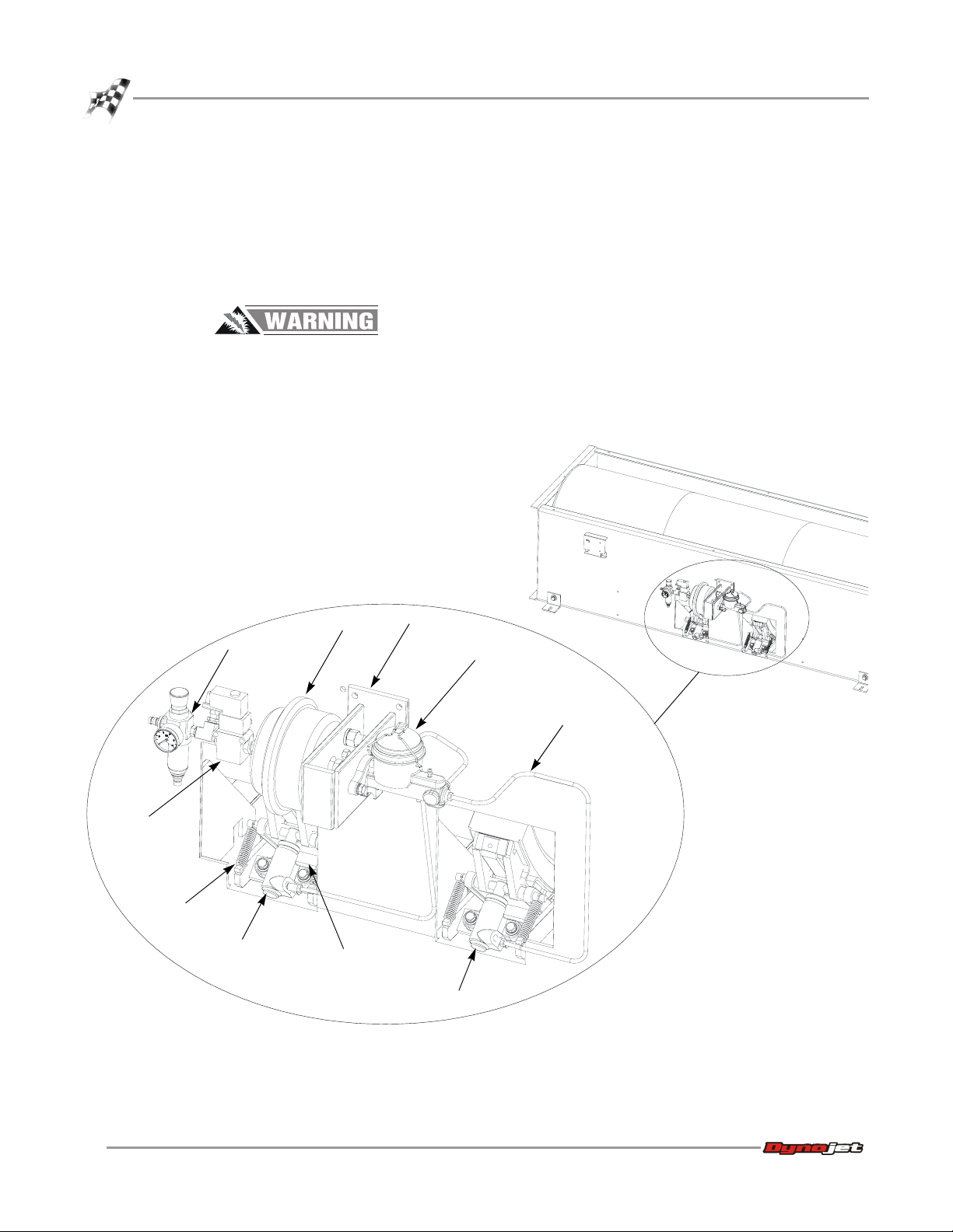
When upgrading to the SAAR Brake Assembly, you will remove the previously installed
hydraulic braking system shown in Figure 2. In order to minimize your exposure to
the fluid used in the hydraulic brake assembly, you will remove the major portion of
the assembly as one piece.
Follow manufacturer precautions for handling brake fluid used in the
hydraulic braking system. Do not breathe vapors, mist, fume or dust. Do not
get in eyes, on skin or clothing. Wear protective gloves or clothing if exposure
conditions warrant. Wash thoroughly after handling. Launder contaminated
clothing before reuse. Use only with adequate ventilation.
solenoid
assembly
spring
slave cylinder
air pressure
regulator
air can
brake clevis
pin
slave cylinder
mounting
bracket
BR011
master cylinder
hydraulic line
Figure 2: Existing Hydraulic Braking System
4
Spring Applied Air Release (SAAR) Brake Assembly Installation
Page 9

SPRING APPLIED AIR RELEASE (SAAR) BRAKE ASSEMBLY INSTALLATION
PREPARING TO REMOVE THE HYDRAULIC BRAKE
1 Turn off the power and unplug the dyno electronics and observe all applicable
safety procedures.
2 Shut off and release the air pressure to the air pressure regulator.
3 Remove covers as necessary to provide yourself good access to the braking
components. Refer to your dyno manuals, if necessary, to review removing the
covers. You can download copies of the manuals for your dyno from
www.dynojet.com.
4 Disconnect the 3/8-inch air hose from the fitting on the pressure regulator, or cut
off the existing air hose close to the fitting on the pressure regulator.
Note: Leave the air hose with the dyno as you will reconnect it to the new
pressure regulator for the SAAR Brake Assembly.
The Hydraulic Brake Assembly
Version 1 Spring Applied Air Release (SAAR) Brake Assembly Installation
5
Page 10

SPRING APPLIED AIR RELEASE (SAAR) BRAKE ASSEMBLY INSTALLATION
The Hydraulic Brake Assembly
5 On standard dynos the brake control wiring is connected to the breakout board.
The breakout board is located on the dyno as shown in Figure 3.
Disconnect the two wires from the wiring block labeled BRAKE on the Breakout
board, as shown in Figure 3. These two wires connect the brake solenoid. It
should now be disconnected.
Note: If you are installing the upgrade on a four-wheel drive dyno, see “Four
Wheel Drive Dynos” on page 20 for the connections of the brake solenoid to the
movement board.
Never operate the dynamometer when the brake is not functioning.
disconnect
brake
assembly
wiring
breakout
board
AD167
BRAKE
Figure 3: Disconnect the Hydraulic Brake Control Wiring from the Breakout Board
6
Spring Applied Air Release (SAAR) Brake Assembly Installation
Page 11

disconnect air
hose or cut air
hose close to
solenoid
BR012
brake head
SPRING APPLIED AIR RELEASE (SAAR) BRAKE ASSEMBLY INSTALLATION
The Hydraulic Brake Assembly
REMOVING THE HYDRAULIC BRAKE ASSEMBLY
1 Remove the four springs holding the brake head pivot pin to the brake frame rail.
pivot pin
brake frame rail
Figure 4: Remove the Springs
2 Use a large flat blade screw driver or small pry bar to pry the brake shoe retainer
out of the brake holder.
pry the brake shoe retainer
out of the brake holder
remove four
springs
brake
holder
Figure 5: Remove the Brake Shoe Retainer
Version 1 Spring Applied Air Release (SAAR) Brake Assembly Installation
7
Page 12

SPRING APPLIED AIR RELEASE (SAAR) BRAKE ASSEMBLY INSTALLATION
The Hydraulic Brake Assembly
3 Remove the brake shoes from the assembly by sliding them to the outside. Set the
brake shoes aside to be reused with the SAAR Brake Assembly.
BR015
slide brake shoes toward
the outside and remove
cotter
pin
BR020
Figure 6: Remove the Brake Shoes
4 Remove the cotter pin from the brake clevis pin on both brakes.
remove
cotter pin
BR022
BR021
slide brake
clevis pin
Figure 7: Remove the Cotter Pins Holding the Brake Hanger Pivots
8
Spring Applied Air Release (SAAR) Brake Assembly Installation
Page 13

SPRING APPLIED AIR RELEASE (SAAR) BRAKE ASSEMBLY INSTALLATION
The Hydraulic Brake Assembly
5 Slide the brake clevis pin into the square recesses provided. The brake clevis pin
will only slide in one direction. You may need to slide your brake clevis pin
opposite to the direction shown in Figure 8 if your brake clevis pin faces the other
way. After you remove the hydraulic brake assembly, you will reach in to remove
the pivot pins from inside the square recesses.
BR016
slide brake clevis pin into
square recess
Figure 8: Slide the Brake Clevis Pin into the Square Recess
Version 1 Spring Applied Air Release (SAAR) Brake Assembly Installation
9
Page 14

SPRING APPLIED AIR RELEASE (SAAR) BRAKE ASSEMBLY INSTALLATION
The Hydraulic Brake Assembly
6 Remove four lower bolts holding the slave cylinders and brake head assembly to
the brake frame rail.
7 Remove the four bolts holding the master cylinder bracket to the dyno,
supporting the hydraulic brake assembly during the final removal of the bolts.
master cylinder bracket
BR017
remove four
bolts
slave cylinder
slave cylinder
remove bolts and washers
Figure 9: Remove Bolts
10
Spring Applied Air Release (SAAR) Brake Assembly Installation
Page 15

BR018
SPRING APPLIED AIR RELEASE (SAAR) BRAKE ASSEMBLY INSTALLATION
The Hydraulic Brake Assembly
8 The hydraulic brake assembly should now be completely free. Remove it from the
dyno.
9 Extract the brake clevis pins from the square recesses and set them aside.
Note: You will reuse the brake shoes and the two clevis pins. The other parts can
be appropriately discarded.
.
remove hydraulic brake
assembly
Figure 10: Remove the Hydraulic Brake Assembly
Version 1 Spring Applied Air Release (SAAR) Brake Assembly Installation
11
Page 16

SPRING APPLIED AIR RELEASE (SAAR) BRAKE ASSEMBLY INSTALLATION
Installing the SAAR Brake Assembly
INSTALLING THE SAAR BRAKE ASSEMBLY
. . . . . . . . . . . . . . . . . . . . . . . . . . . . . . . . . . .
The following instructions are for installing the Spring Applied Air Brake Assembly on
a 224 above-ground or pit dyno.
In the next steps you will:
• attach the brake holder weldment using the brake clevis pin you removed
from the hydraulic brake assembly
• bolt the mounting bracket to the dyno
• slide the tube into place
• mount the air can assembly
• make the final connections
Note: If you have a 4 wheel drive dyno model 224-248 or 224-224, refer to
additional instructions for “Four Wheel Drive Dynos” on page 20.
INSTALLING THE BRAKE WELDMENT AND BRAKE SHOES
1 Slide the brake clevis pins into the square recesses as shown in Figure 11. Face
the head end of the pivot toward the outside, so that the brake clevis pin is
partially inside the recess and then slide the clevis pin partially into the mounting
bracket. The hole on the end of the brake clevis pin, which is designed to accept
the hairpin cotter, should be pointed toward the center of the dyno. Do not fully
insert the brake clevis pin until after you slide the brake weldment into position
2 Position the brake weldment so that the holes on the arms are aligned to accept
the brake clevis pin.
slide brake clevis
pin into position
BR024
Figure 11: Slide Brake Weldment into Position
12
Spring Applied Air Release (SAAR) Brake Assembly Installation
brake holder weldment
brake arms
Page 17

SPRING APPLIED AIR RELEASE (SAAR) BRAKE ASSEMBLY INSTALLATION
Installing the SAAR Brake Assembly
3 Insert the brake clevis pin through the holes as shown in Figure 12.
4 Install the hairpin cotter.
5 Use the same method to install the remaining brake weldment with arms, pivot,
and hairpin cotter.
head end of
brake clevis pin
BR025
insert
hairpin cotter
brake shoe
Figure 12: Connect the Brake Weldment and Arms using the Brake Clevis Pin
6 Slide the brake shoe into position and thread the brake shoe retainer into
position. (Now is a good time to check for wear and use new brake shoes if
necessary, P/N 33831001.)
brake shoe
retainer
brake shoe
installed
BR031
brake shoe retainer
installed
Figure 13: Install the Brake Shoes
Version 1 Spring Applied Air Release (SAAR) Brake Assembly Installation
13
Page 18

SPRING APPLIED AIR RELEASE (SAAR) BRAKE ASSEMBLY INSTALLATION
Installing the SAAR Brake Assembly
INSTALLING THE AIR CAN MOUNT AND TUBE
1 Install the air can mount using the four 3/8"-16 x 1-1/2" flange bolts provided
BR027
four 3/8"-16 x 1-1/2"
flange bolts
air can mount
air can assembly
Figure 14: Attach the Air Can Mount to the Dyno
14
Spring Applied Air Release (SAAR) Brake Assembly Installation
Page 19

SPRING APPLIED AIR RELEASE (SAAR) BRAKE ASSEMBLY INSTALLATION
Installing the SAAR Brake Assembly
2 Slide the tube through the brake arms.
3 Rotate the tube so that the center hole is oriented vertically.
BR028
slide tube through arms
orienting the hole
vertically
Figure 15: Slide the Tube into Place
Version 1 Spring Applied Air Release (SAAR) Brake Assembly Installation
15
Page 20

SPRING APPLIED AIR RELEASE (SAAR) BRAKE ASSEMBLY INSTALLATION
Installing the SAAR Brake Assembly
INSTALLING THE AIR CAN
1 Thread the pipe fitting which extends from the solenoid subassembly into the
threaded hole on the top of the air can. Apply pipe thread sealer to the fitting if
sealer is not already present.
2 Align the solenoid assembly so that it is parallel to the two bolts that extend from
the bottom of the air can as shown in Figure 17.
AB093
threaded pipe fitting
solenoid assembly
threaded hole
in air can
3 Remove and set aside the two 5/8" lockwashers and nuts for the air can.
4 Remove and set aside the 5/8" nut from the long threaded rod at the bottom of
5/8" lockwashers
and nuts
air can
Figure 16: Attach the Solenoid Subassembly to the Air Can
the air can.
BR030
align solenoid assembly
with these two studs
5/8" nut
Figure 17: Prepare the Air Can Assembly
16
Spring Applied Air Release (SAAR) Brake Assembly Installation
Page 21

SPRING APPLIED AIR RELEASE (SAAR) BRAKE ASSEMBLY INSTALLATION
Installing the SAAR Brake Assembly
5 While lowering the air can through the hole in the tube, align the air can studs
with the holes in the bracket.
Note: The rod will not extend all of the way through the tube until the electronics
are connected and air pressure is applied to the air can.
6 Loosely attach the air can to the bracket using the two 5/8" nuts and lockwashers
removed earlier.
Keeping the nuts loose will allow for adjustment while extending the air can rod
the remaining distance through the tube. The power and air connections are
necessary to finish connecting the brake assembly.
air can studs
washer and upper nut
will be tightened down
onto tube after lower
nut is fastened
use 5/8" lockwashers
and nuts to attach air
can to bracket
BR029
Figure 18: Install the Air Can
insert air can rod into
hole through tube
Version 1 Spring Applied Air Release (SAAR) Brake Assembly Installation
17
Page 22

SPRING APPLIED AIR RELEASE (SAAR) BRAKE ASSEMBLY INSTALLATION
Installing the SAAR Brake Assembly
CONNECTING TO THE BREAKOUT BOARD
1 Connect the two black wires from the solenoid to the two terminals on the
breakout board labelled BRAKE (one to each terminal).
2 If you have a 4 wheel drive dyno model 224-248 or 224-224, refer to additional
instructions for “Four Wheel Drive Dynos” on page 20.
connect the two black
wires from the brake
solenoid to the
breakout board
CONNECTING TO THE SHOP AIR
BRAKE
Figure 19: Connect the Brake Solenoid Wires to the Breakout Board
1 Connect shop air to the fitting on the brake air can pressure regulator. See
Figure 22 on page 21 if you are installing the brake on a four-wheel drive dyno.
2 Adjust the air pressure by pulling up on the regulator knob and turning
counterclockwise to decrease the pressure to 30 psi (clockwise to increase).
Note: The Spring Applied Brake should be operated at 100 psi, but you will start
with the pressure lower while connecting the air can to aid in lining up the parts.
pull up on regulator
knob and adjust
pressure to 30 psi
0
AB092
18
Spring Applied Air Release (SAAR) Brake Assembly Installation
pressure gauge
should read 30 psi
Figure 20: Adjust the Air Pressure
Page 23

SPRING APPLIED AIR RELEASE (SAAR) BRAKE ASSEMBLY INSTALLATION
FASTENING THE AIR CAN
1 Check to make sure that the area is clear and that the dyno can be operated safely.
2 Power up the dyno electronics.
Keep hands and fingers clear when operating dyno.
3 Use the pendant to turn the brake to the OFF position. This will apply air pressure
to the brake’s air can to extend the rod, allowing you to fit the rod through the
bottom of the hole in the brake actuating tube.
4 Gradually increase the air pressure to 100 psi by pulling up on the regulator knob
and turning it clockwise. As you are doing this, guide the air can rod through the
hole in the brake actuating tube.
5 Torque the upper two nuts fastening the air can to the mounting bracket to
110 ft-lbs.
6 Adjust the nut on the bottom of the air can rod until the brake shoes are
6mm/.25" away from the dyno drum.
7 Tighten the upper nut on the air can rod down onto the brake actuating tube to
sandwich the tube between the two nuts.
8 Torque the lower nut to 110 ft-lbs.
Installing the SAAR Brake Assembly
Your brake should now be completely installed
.
connect the two black
wires from the brake
solenoid to the
breakout board
connect to shop air
Figure 21: Apply Air Pressure to Extend Air Can Rod into Brake Actuating Tube
POWERING UP AND TESTING
torque nuts to
110 ft-lbs
air can rod
upper nut
BR032
torque lower nut
to 110 ft-lbs
1 Verify that the pressure gauge on the Spring Applied Air Brake shows 100 psi.
2 Use the pendant to turn the brake ON.
3 Ensure that the brake shoes are making contact with the dyno’s drum and that the
drum will not rotate.
Adjust the brake if necessary using the nuts on the air can rod.
Version 1 Spring Applied Air Release (SAAR) Brake Assembly Installation
19
Page 24

SPRING APPLIED AIR RELEASE (SAAR) BRAKE ASSEMBLY INSTALLATION
Four Wheel Drive Dynos
FOUR WHEEL DRIVE DYNOS
. . . . . . . . . . . . . . . . . . . . . . . . . . . . . . . . . . .
The instructions in the following sections describe the differences for installing the
SAAR Brake Assembly on four-wheel drive dynos. The SAAR Brake Assembly may be
used to upgrade the braking on 224-248 model and 224-224 four-wheel drive dynos.
The 224-248 dyno has a stationary 248 dyno and a moveable 224 dyno. When
upgrading this model, you will leave the existing air applied brake on the stationary
248 dyno and only upgrade the moveable 224 dyno.
The model 224-224 dyno uses a stationary 224 dyno along with a moveable 224 dyno
that can be positioned to accommodate for the wheelbase of the vehicle being
tested.When upgrading a model 224-224, both 224 dynos must have the SAAR Brake
Assembly upgrade. To upgrade the stationary dyno, follow the directions in the
previous sections of the manual.
UPGRADING THE MOVEABLE 224 DYNO
Moveable 224 dynos use a control box containing the dyno movement board and
other movement components. The wiring to the brake solenoid is connected to the
movement board in the control box and not the breakout board, as in the standard
installation instructions.
In general, when installing a SAAR brake on a moveable 224 dyno, follow the
instructions in the manual, except when disconnecting and connecting the brake
control wiring and air. Use the steps that follow to connect the brake wiring to the
movement board and to connect the air supply to the SAAR brake.
CONNECTING THE MOVEMENT BOARD AND SHOP AIR
The movement board is located inside the control box as shown in Figure 22.
1 Disconnect one black wire and one white wire from the movement board
terminals labelled BRK2 that connect the existing brake solenoid.
2 Route the wires for the new brake solenoid through the opening in the control
box and connect the two black wires to the terminals labelled BRK 2 on the
movement board. (Connect one to each terminal, the order does not matter as
the solenoid will operate correctly with either polarity.)
3 Connect the air hose to the solenoid, replacing the hose if necessary.
4 Continue the installation with step #2, “Connecting to the Shop Air” on page 18.
20
Spring Applied Air Release (SAAR) Brake Assembly Installation
Page 25

SPRING APPLIED AIR RELEASE (SAAR) BRAKE ASSEMBLY INSTALLATION
Four Wheel Drive Dynos
control box
connect air
hose to
solenoid,
replace hose
if needed
BR033
IN BRK 1BRK 2
OUTRAIL
connect the two black wires
from the brake solenoid to
the terminals labelled
BRK 2 on movement board
+12V GND OUTINCOMBRK IN
movement board
-- PRES SW
Figure 22: Connect from Solenoid to the Movement Board in the Control Box
Version 1 Spring Applied Air Release (SAAR) Brake Assembly Installation
21
Page 26

Page 27

 Loading...